Hi,
I'm not sure I understand what you're asking. If the belt is on, you can't turn the cam independently. Do me a favor. Here are the directions for belt replacement. It shows all timing marks and procedures. The attached pics correlate with the directions. Take a look through them and see if they help.
__________________________________
2005 Kia Truck Sedona V6-3.5L
Procedures
Vehicle Engine, Cooling and Exhaust Engine Timing Components Timing Belt Service and Repair Procedures
PROCEDURES
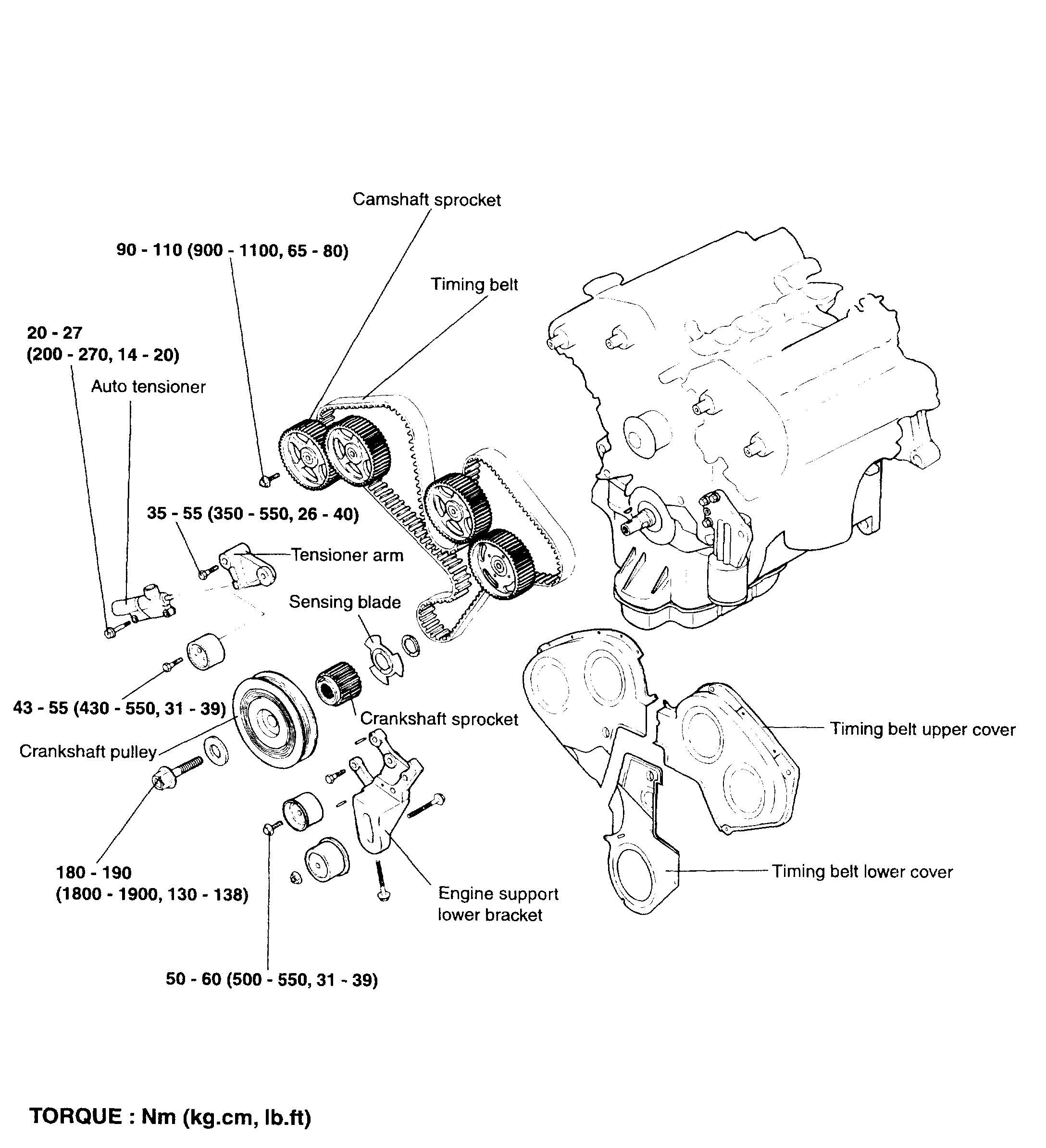
pic 1
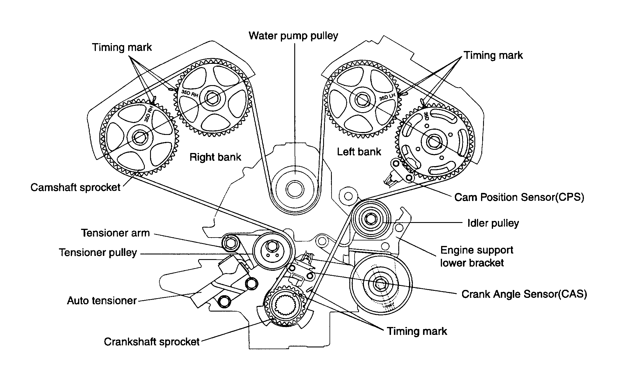
pic 2
REMOVAL
1. Remove the engine cover.
2. Remove the drive belt.
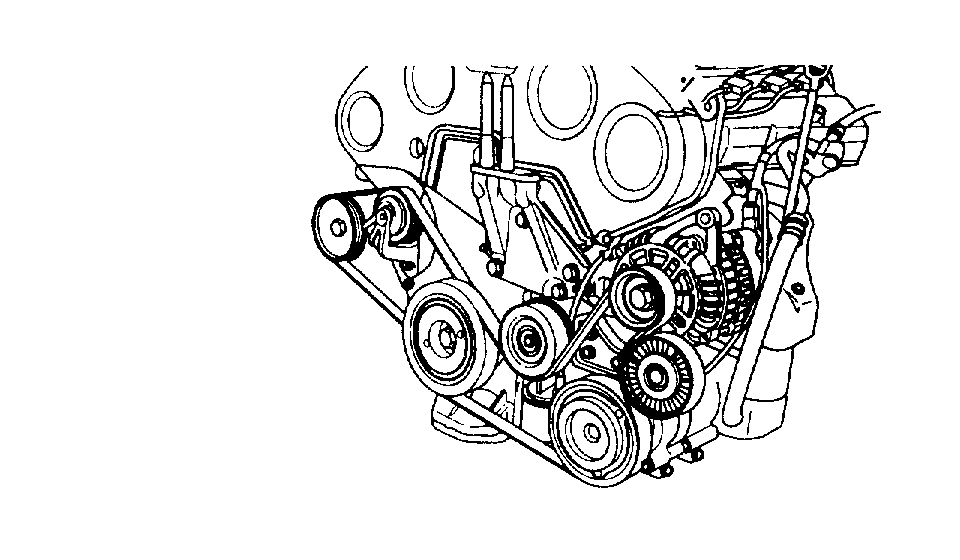
pic 3
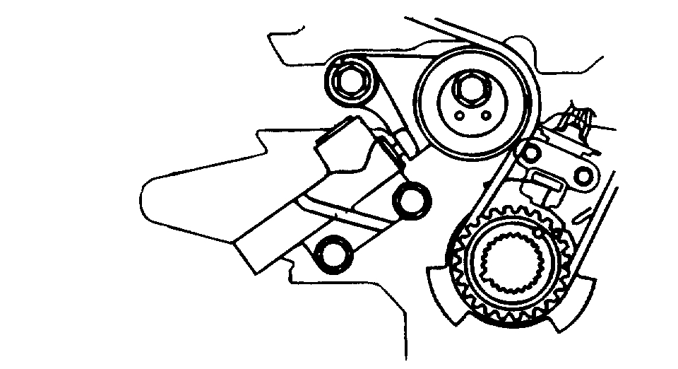
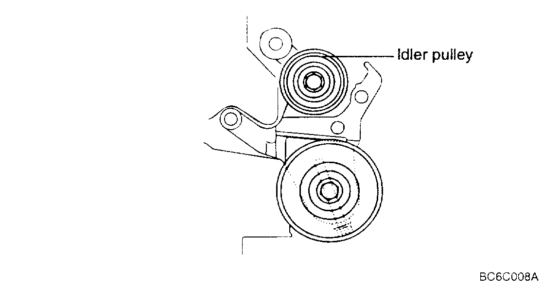
3. Remove the idler pulley, crankshaft pulley, power steering pulley and tensioner pulley.
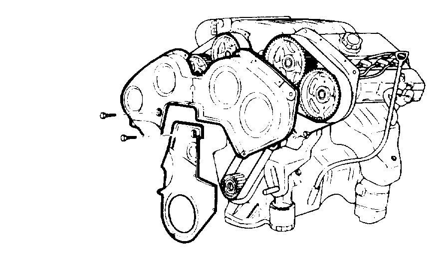
pic 4
4. Remove the upper and lower timing belt cover.
5. Support the engine with garage jack or special tool, and then remove the engine mounting insulator.
CAUTION: Take care not to deform the engine oil pan.
pic 5
6. Remove the auto tensioner.
NOTE: Rotate the crankshaft clockwise and align the timing mark to get the No. 1 cylinder's piston be in TDC position (compression stroke).
At this time, the timing marks of the camshaft sprocket and cylinder head cover should coincide with each other.
pic 6
7. Remove the timing belt.
NOTE: When re-using timing belt, make sure of marking the rotating direction on the belt so as to install correctly.
INSPECTION
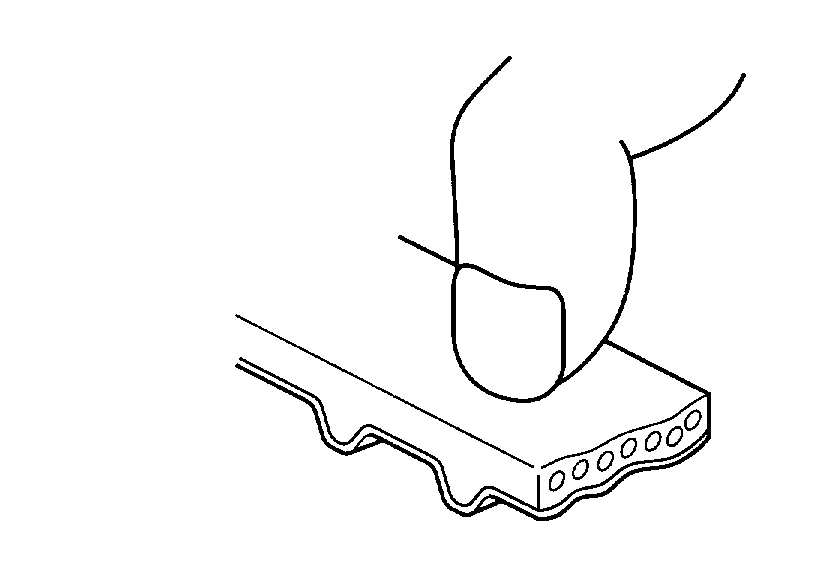
1. Check the belt carefully and if any damage is found, exchange it with a new one.
pic 7
1. Vulcanization of the rubber backside. The backside is glossy and non-elastic so that, even if a finger nail is forced into it, no mark is produced.
pic 8
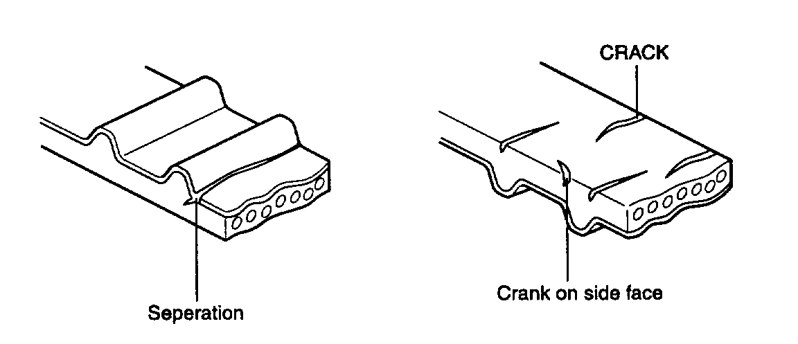
2. Crack on the rubber belt surface.
pic 9
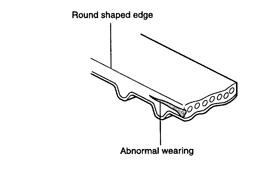
3. Abnormal wearing of side face of belt.
CAUTION: Belts in good condition seem to be cut by a sharp knife.
pic 10
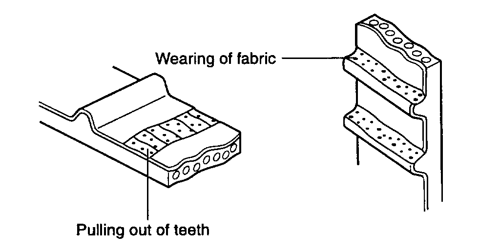
4. Abnormal tooth wearing
Initial stage
Wearing of side face of load exerting tooth (Fabric puff up, rubber material peel off with color changing to white and fabric become uneven and rough).
Last stage
Fabric wearing of side face of load exerting tooth occurs and rubber is exposed (Length between teeth decrease.).
5. Missing tooth.
pic 11
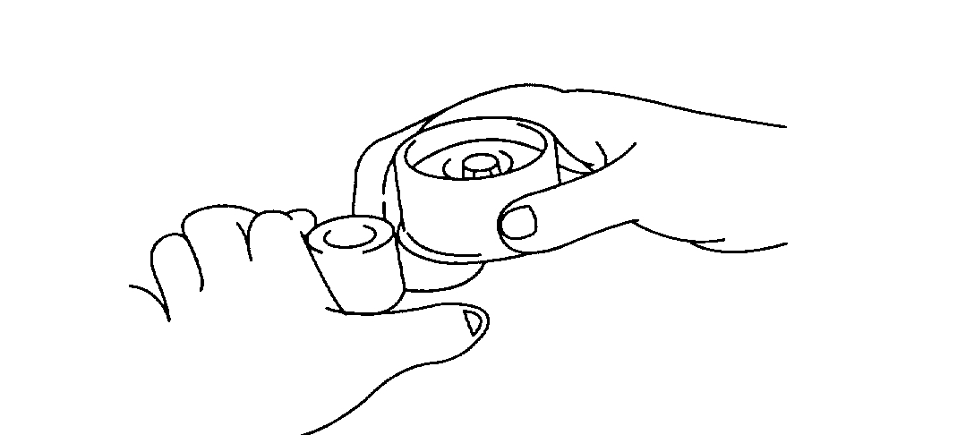
2. If any abnormal noise or difficulty in rotating the pulley by hand is noticed, replace the timing belt tensioner and idler pulley.
INSTALLATION
METHOD OF INSTALLING TIMING BELT AND AUTO TENSIONER
pic 12
1. Install the idler pulley to the engine support lower bracket.
pic 13
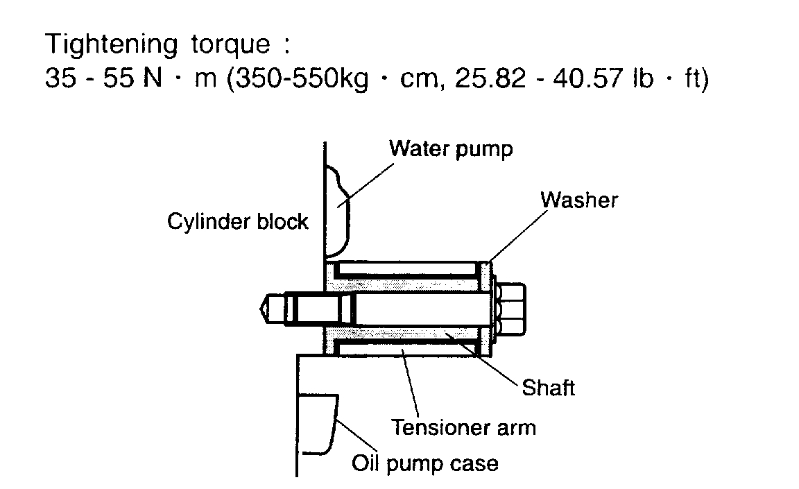
2. Install the tensioner arm, shaft and plain washer to the cylinder block.
pic 14
pic 15
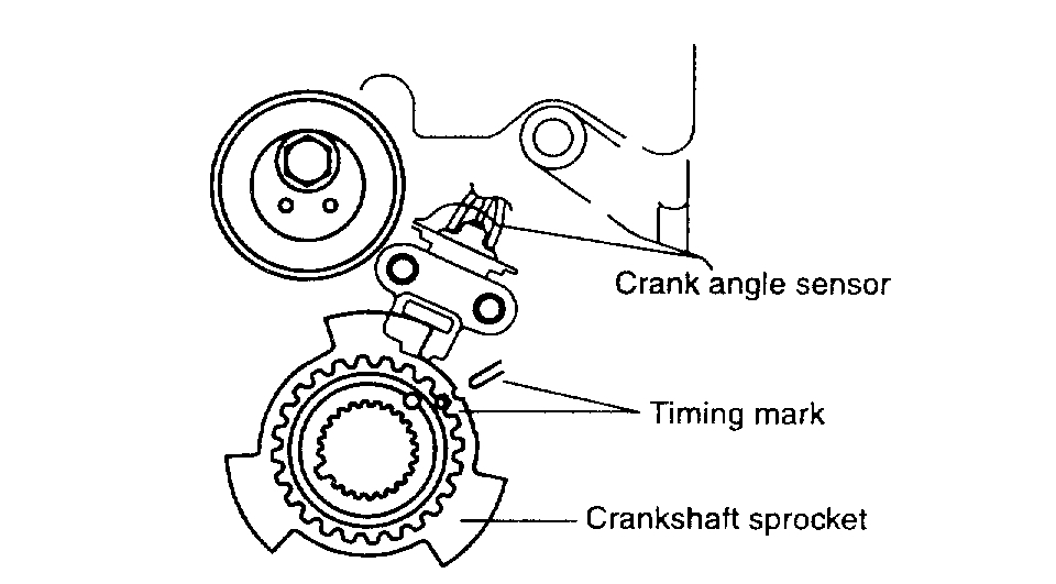
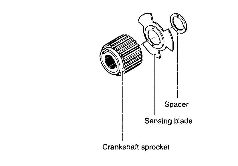
3. Install the crankshaft sprocket.
NOTE: Confirm if timing marks coincide with.
CAUTION: Align the spacer with a pin, and assemble it exerting even force not to deform the crankshaft sensing blade.
pic 16
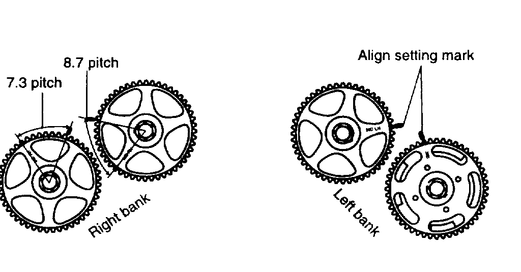
4. Install the camshaft sprocket. Align it like initial state.
CAUTION: When installing camshaft sprocket, tighten the bolt holding hexagonal part of camshaft to prevent it from turning.
pic 17
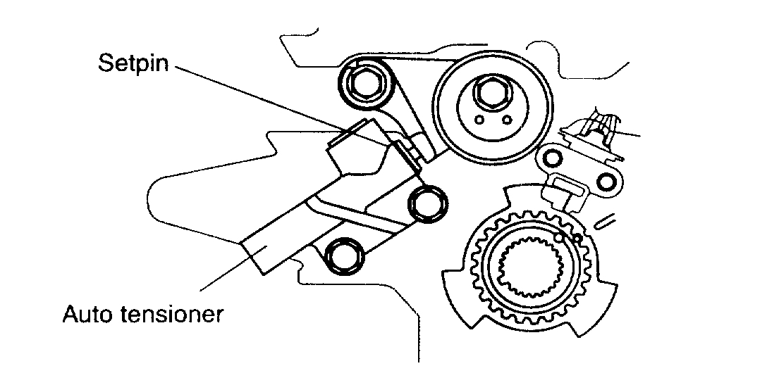
5. Install the auto tensioner to the oil pump case.
CAUTION: At this time the auto tensioner's set pin should be assembled completely.
pic 18
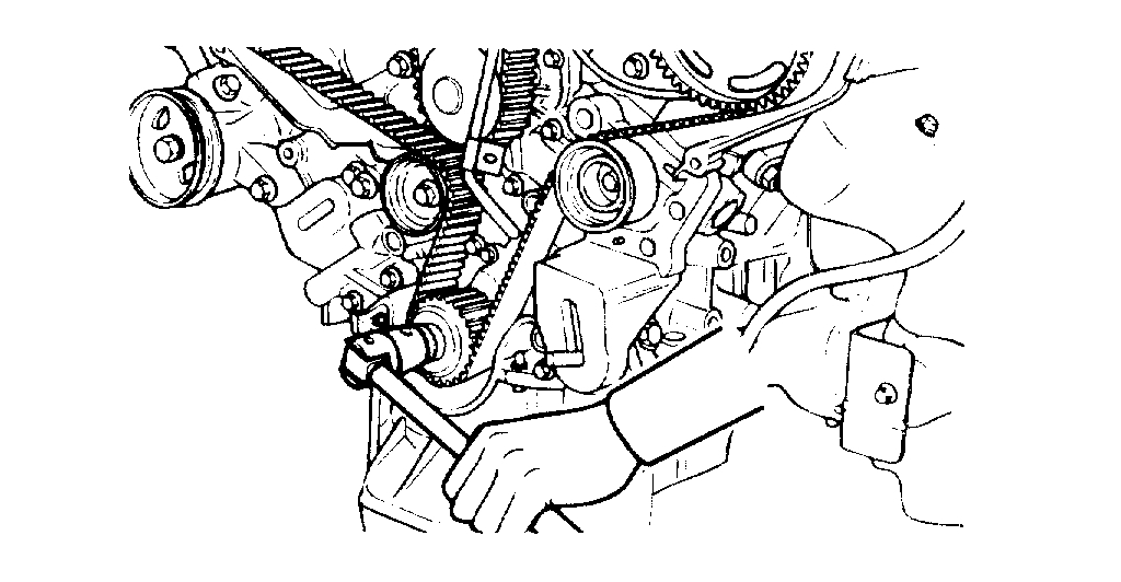
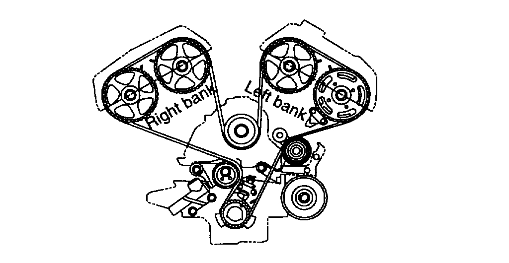
6. Align the timing marks of each sprocket and install the timing belt, maintaining the proper belt tension between each shaft in this order.
Crankshaft sprocket -> Idler pulley -> Left bank exhaust camshaft sprocket -> Left bank intake camshaft sprocket -> Water pump pulley -> Right bank intake camshaft sprocket -> Right bank exhaust camshaft sprocket -> Tensioner pulley.
CAUTION:
- As a result of this, position of No.1 cylinder comes to compression TDC.
- As each camshaft sprocket tends to rotate by itself, pay attention not to injure fingers or other bodily part. Especially be careful with the right bank.
- In case the right bank camshaft sprocket rotates excessively, be cautious not to rotate more than the initial stable position. Always align timing mark of rotating sprocket by turning it reversely. In this case, pay attention not to rotate it reversely from the initial position. (if, with one sprocket fixed at No. 1 compression TDC position, the other sprocket is rotated one revolution clockwise or counter clockwise, then the intake and exhaust valve might interfere each other.)
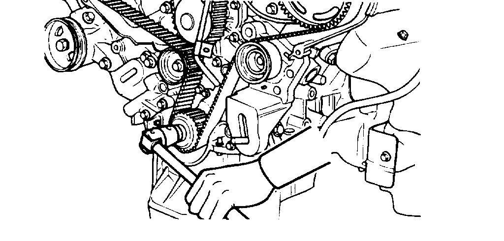
7. After installing the timing belt, exert the reverse-directed force to the right bank exhaust camshaft sprocket to give tension on the belt. Holding this state, recheck if each timing mark is correctly positioned.
pic 19
8. With tensioner pulley slightly pushing the belt down, tighten the center bolts lightly.
9. Pull out the auto tensioner set pin.
HOW TO ADJUST TIMING BELT TENSION
1. Tension setting (While auto tensioner is not operating
: And set pin being kept installed.).
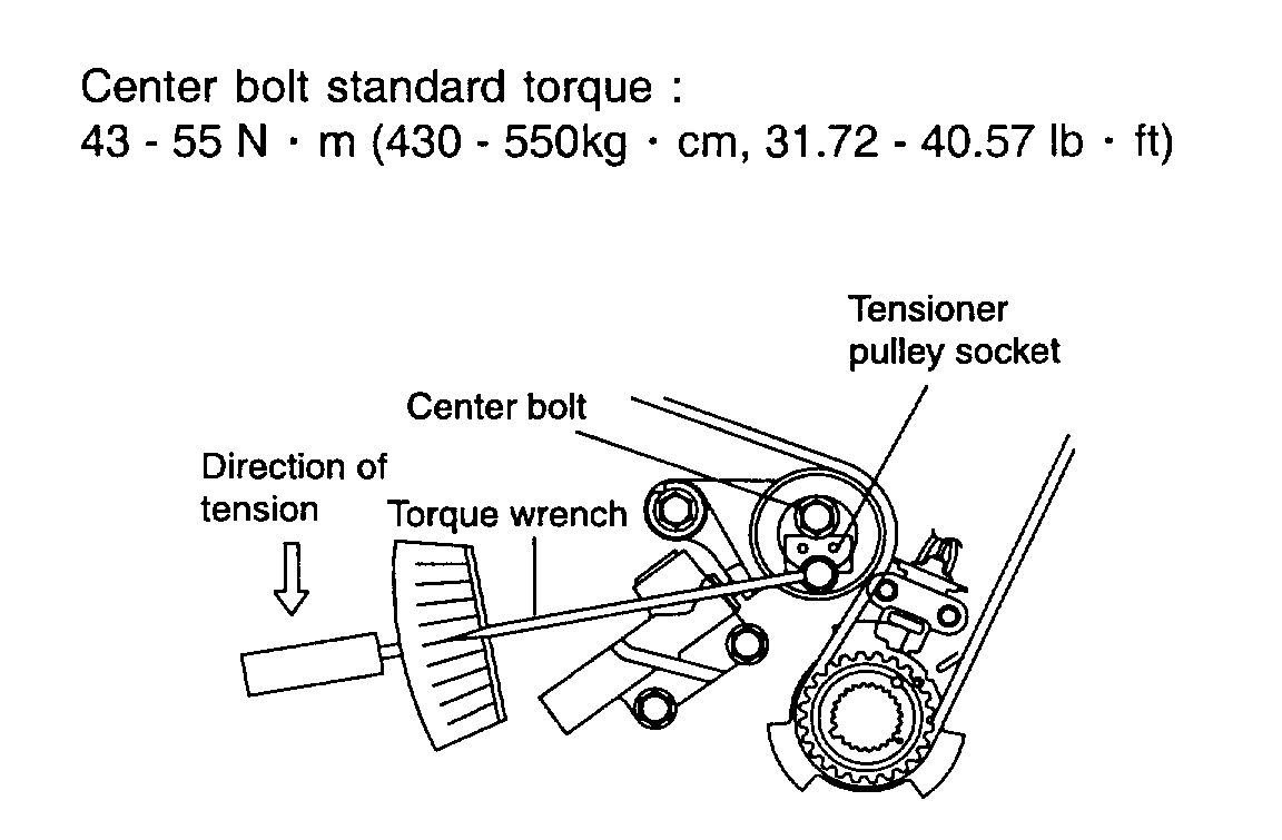
pic 20
1. After rotating crankshaft 1/4 revolution reversely, rotate it clockwise to position No. 1 cylinder at TDC.
Then, loosen the center bolt and give the belt 50 kg-cm of tension with tensioner pulley socket (Two pins are attached) and torque wrench. While maintaining this state, tighten the center bolt to the standard torque.
Timing Belt Tension Socket Wrench P/N: 09244-28100
pic 21
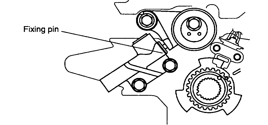
2. Pull out the auto tensioner fixing pin.
pic 22
2. How to check tension (While auto tensioner is operating : and fixing pin being uninstalled.)
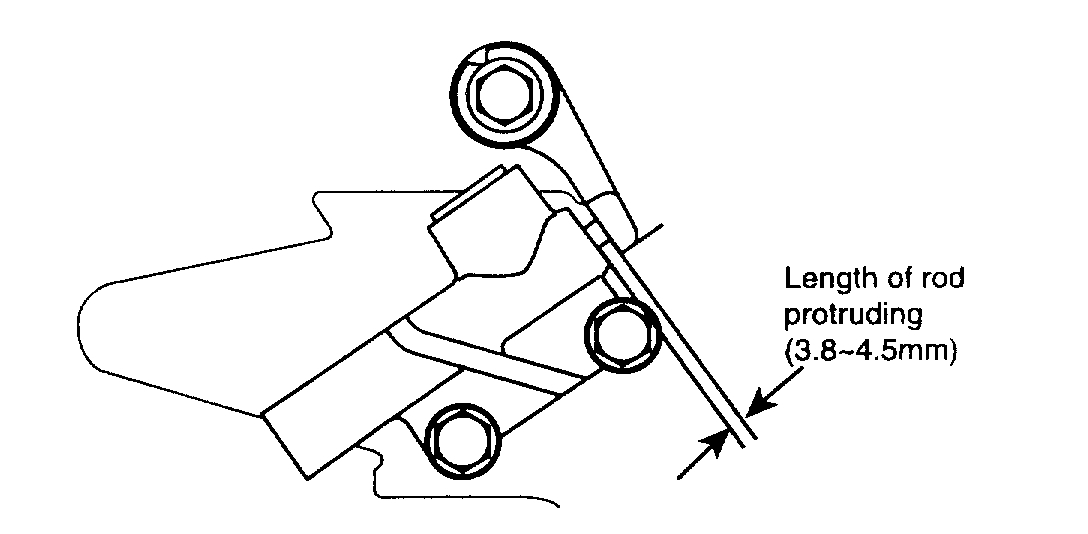
1. After rotating crankshaft 2 revolutions clockwise to position No. 1 cylinder at TDC, wait for about 5 minutes, and measure the amount of protruding of the auto tensioner rod.
CAUTION: This is "leak down" time for the auto tensioner rod to protrude 1 mm when tension caused by rotation of the crankshaft has changed.
2. Check if the amount of rod protruding is in the range of 3.8 - 4.5 mm.
3. Recheck if each sprocket is within the specified range.
NOTE: If it is not within the specified range, repeat from procedure 6 as service procedure of timing belt and auto tensioner installation method.
___________________________________________________
I hope this helps. Let me know if you have other questions.
Take care and God Bless,
Joe
Images (Click to enlarge)
Feb 19, 2021 at 6:41 PM