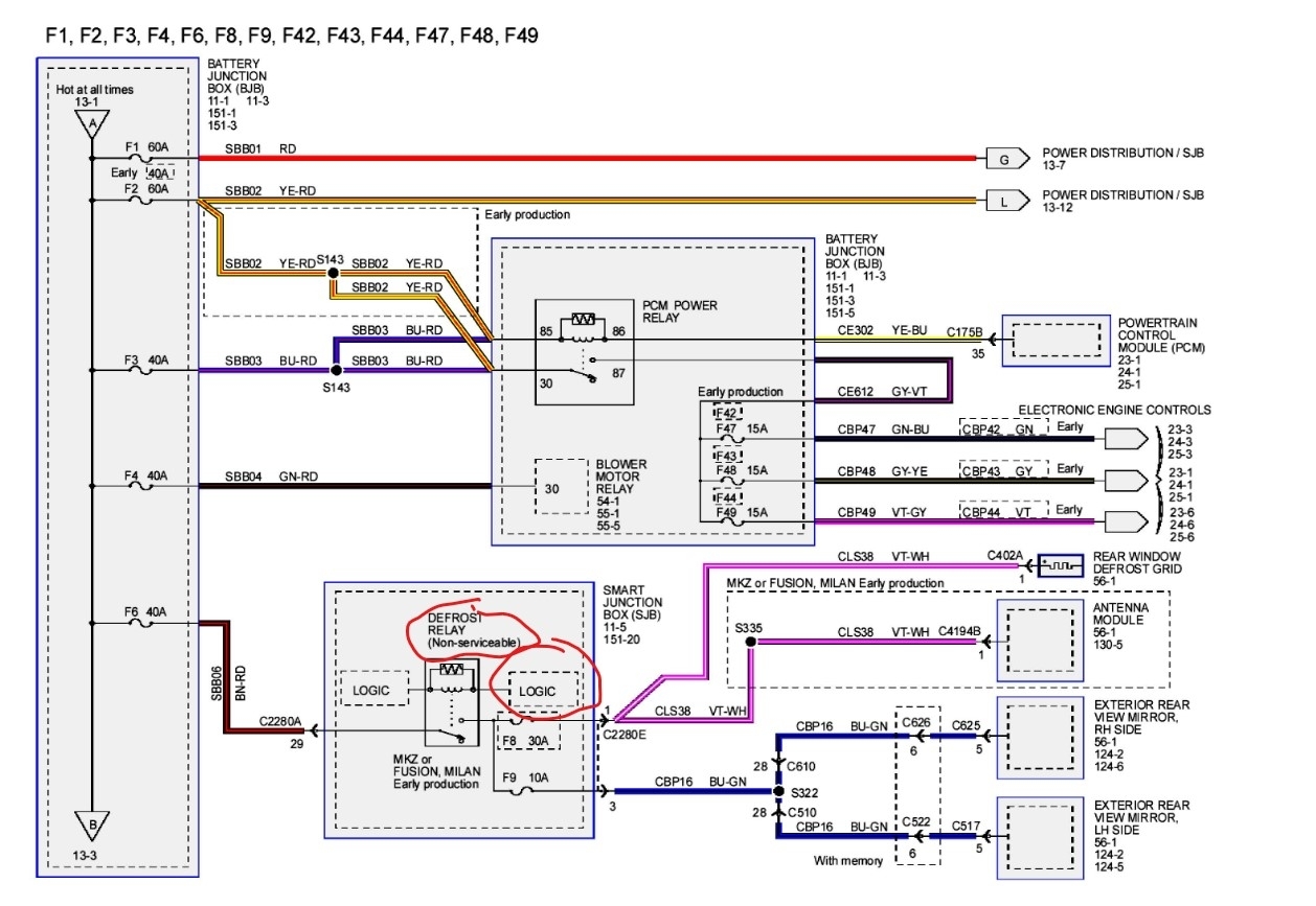
Okay so, in the engine compartment there are 3 different fuses.
Fuse NO. 1 (60A) SJB Power Fed Fuse
12,13,14,15,16,17,18 C/B
So, my question is this, are those fuse numbers for the inside of the vehicle or in the engine compartment fuse box and also what does this fuse really mean and what does the C/B mean?
Fuse NO. 19 (40A) Logic Fed to SJB
What does this fuse mean?
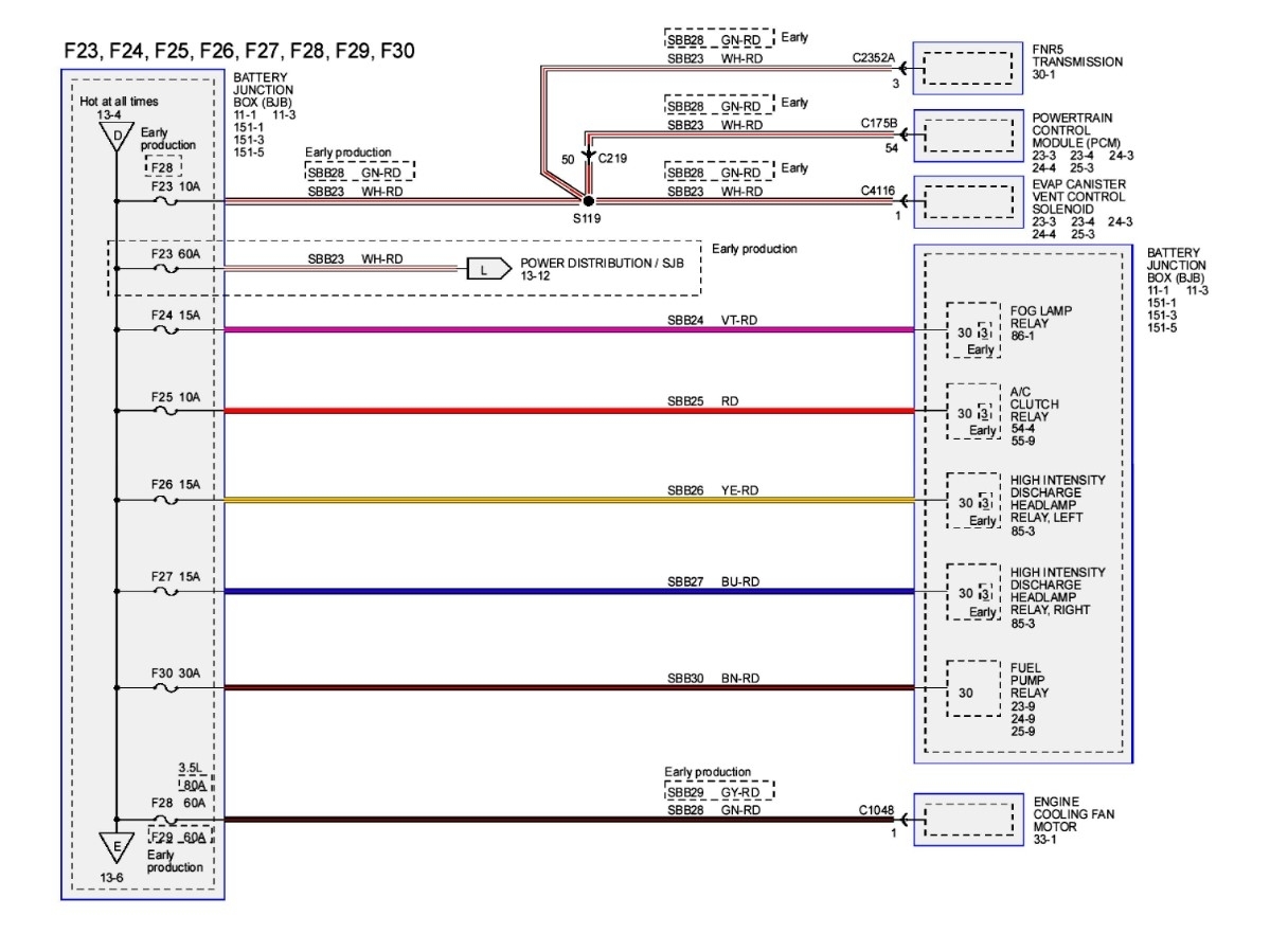
Fuse NO. 23 (60A) SJB Power Fed Fuses
1,2,4,10,11
Is this like the top fuse i first asked about?
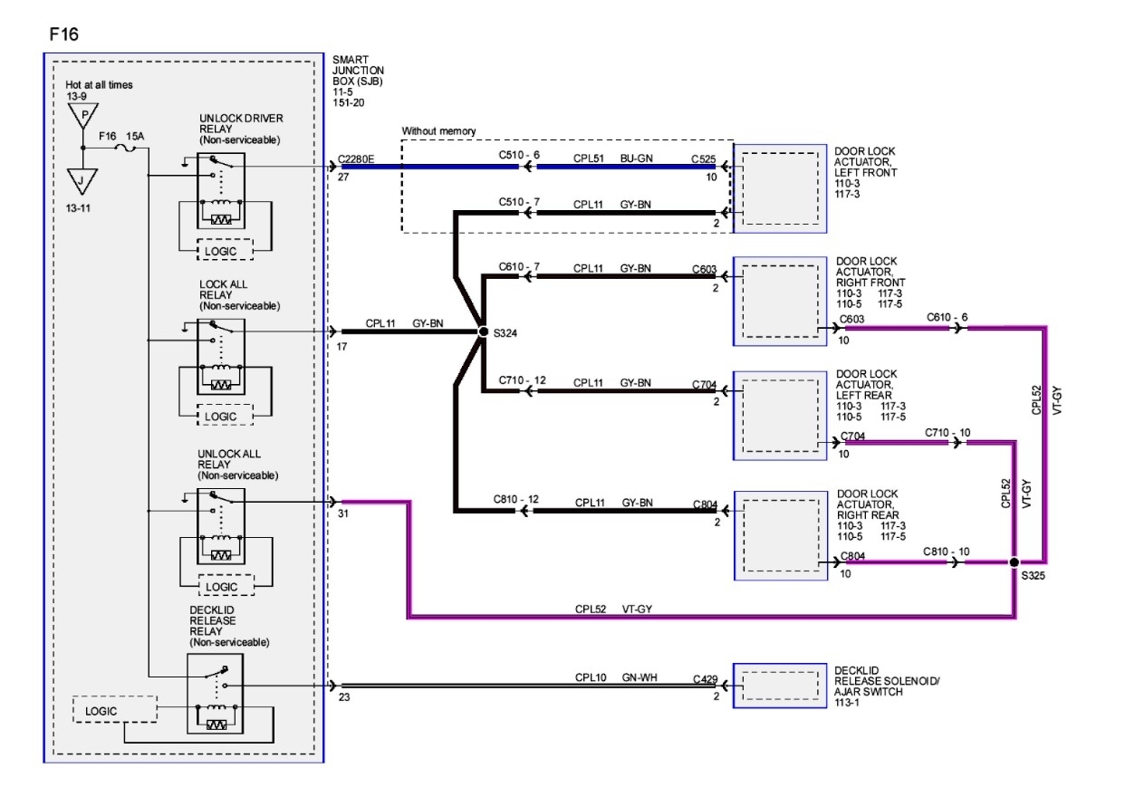
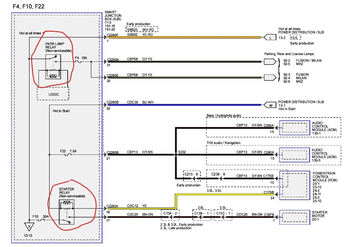
The only reason for my question is i am trying to understand how the SJB box works and functions and what if any fuses does it controls. i have worked on many different cars but never had to deal with an SJB. i am just trying to understand and clarify what this is and how it all works.
Fuse NO. 1 (60A) SJB Power Fed Fuse
12,13,14,15,16,17,18 C/B
So, my question is this, are those fuse numbers for the inside of the vehicle or in the engine compartment fuse box and also what does this fuse really mean and what does the C/B mean?
Fuse NO. 19 (40A) Logic Fed to SJB
What does this fuse mean?
Fuse NO. 23 (60A) SJB Power Fed Fuses
1,2,4,10,11
Is this like the top fuse i first asked about?
The only reason for my question is i am trying to understand how the SJB box works and functions and what if any fuses does it controls. i have worked on many different cars but never had to deal with an SJB. i am just trying to understand and clarify what this is and how it all works.
Sep 23, 2022 at 7:46 PM