Hi,
I am going to provide the directions and diagrams below, related to everything in the rear door. The attached pics will correlate with the directions. Take a look through it to see if there is something that will help. Don't be overwhelmed with these directions. It is for everything. Look for the sections needed. Note there are four parts to these directions. If you look at the first 4 pictures below, it shows all the different parts each section refers to. If you don't see what you need in these directions, look at the first 4 pics, identify what section you need, and let me know.
OVERHAUL
HINT:
- The installation is in the reverse order of the removal. However, when there is a special point concerning the installation, it is indicated.
- On the RH side, use the same procedures as on the LH side.
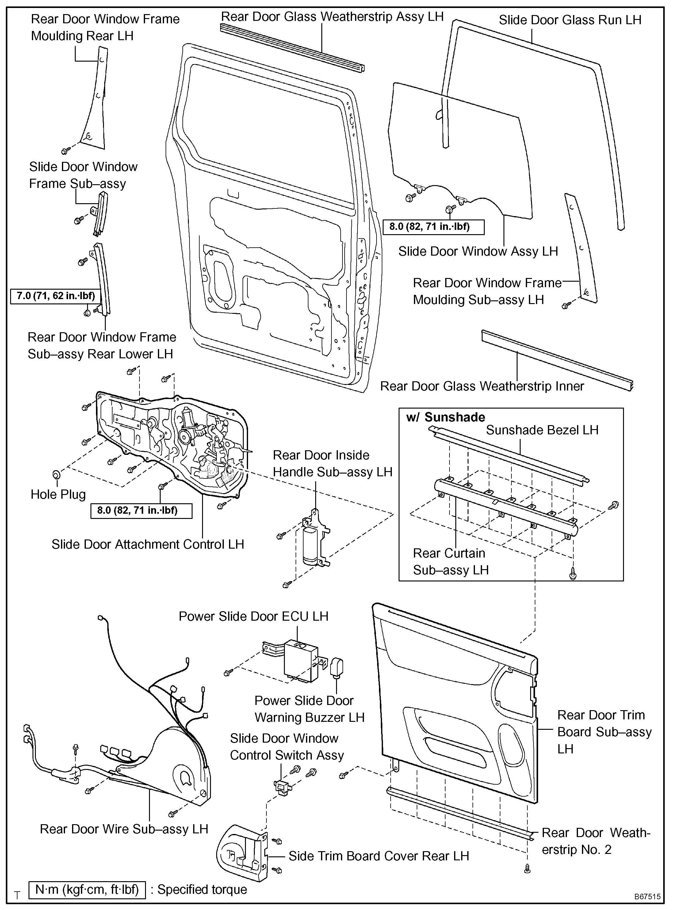
1. REMOVE REAR DOOR WINDOW FRAME MOULDING REAR LH
2. REMOVE REAR DOOR WINDOW FRAME MOULDING SUB-ASSEMBLY LH
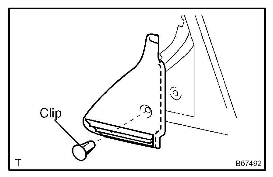
3. REMOVE SLIDE DOOR WINDOW GARNISH LH
a. Fully open the slide door window.
b. Remove the glass run.
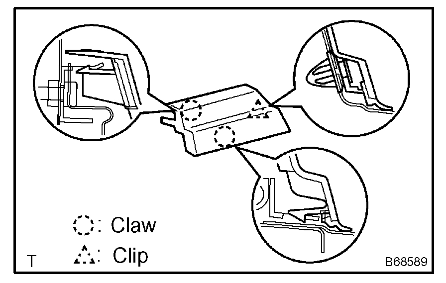
c. Using a screwdriver, disengage the clip and remove the garnish.
HINT: Tape the screwdriver tip before use.
d. Using a screwdriver, disengage the 2 claws and remove the weatherstrip inner from the garnish.
HINT: Tape the screwdriver tip before use.
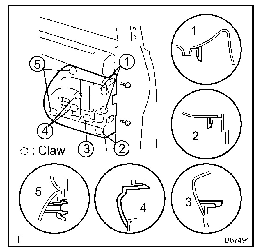
4. REMOVE SIDE TRIM BOARD COVER REAR LH
a. Remove the 2 screws.
b. Using a screwdriver, disengage the 8 claws and remove the cover together with the window control switch.
HINT: Tape the screwdriver tip before use.
c. Remove the 2 screws and window control switch.
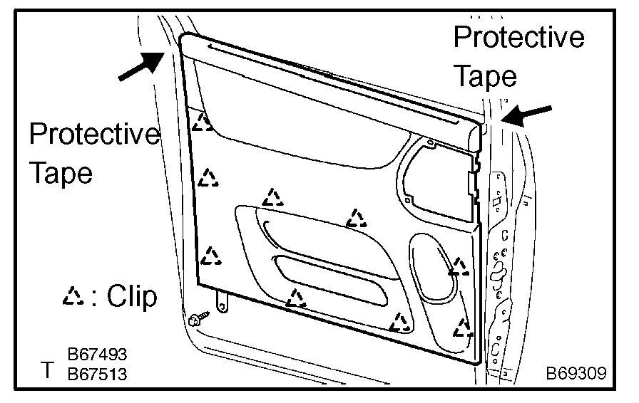
5. REMOVE REAR DOOR TRIM BOARD SUB-ASSEMBLY LH
a. Remove the screw.
b. Using a screwdriver, disengage the 9 clips and remove the trim board.
HINT:
- Tape the screwdriver tip before use.
- In order to prevent the door panel from being damaged, cover the areas with protective tape as indicated by arrow marks in the illustration.
c. Using a clip remover, remove the 6 clips and weatherstrip No. 2.
d. Using a screwdriver, disengage the 11 claws and remove the weatherstrip inner from trim board.
HINT: Tape the screwdriver tip before use.
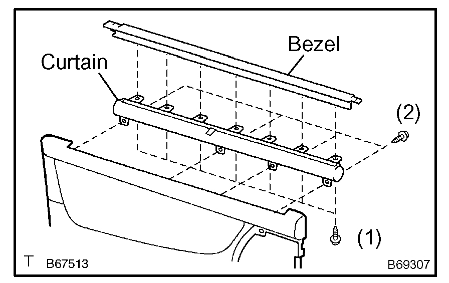
e. W/ Sunshade:
Remove the sunshade.
1. Remove the 7 screws and sunshade bezel.
2. Remove the 4 screws and curtain.
6. REMOVE SLIDE DOOR WINDOW ASSEMBLY LH
a. W/ Sunshade:
Remove the sun shade hook.
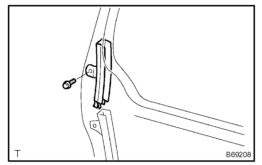
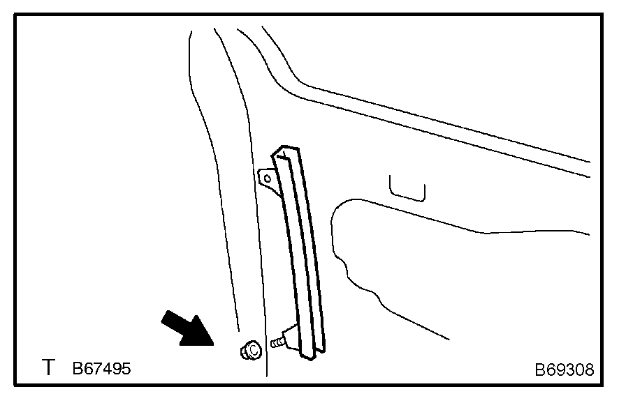
b. Remove the bolt and window frame.
c. Remove the bolt.
d. Loosen the nut.
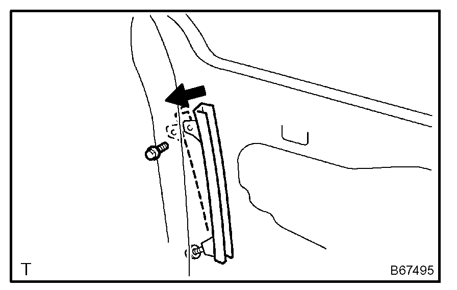
e. Push the window frame rear lower in the direction indicated by the arrow mark in the illustration.
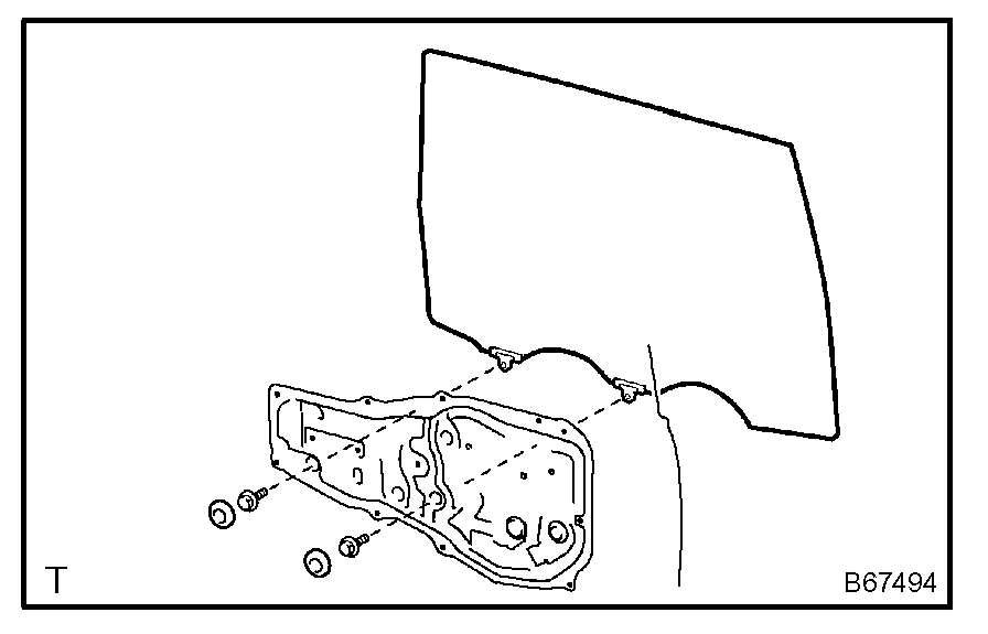
f. Remove the 2 hole plugs.
g. Move the window until the bolts appear in the service holes.
NOTE:
- Do not damage the window.
- When the bolts are removed, the window may fall and become deformed.
h. Remove the 2 bolts and window.
7. REMOVE REAR DOOR GLASS WEATHERSTRIP ASSEMBLY OUTER LH
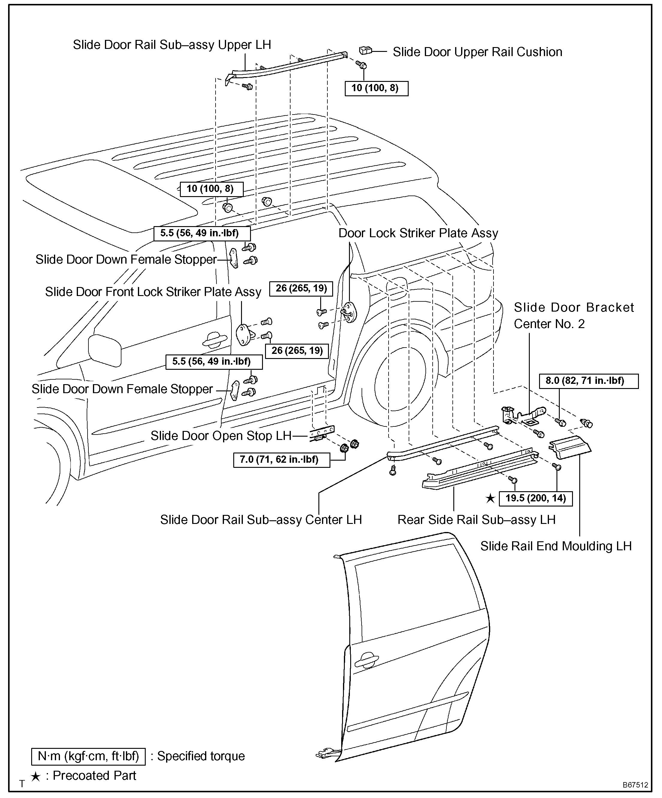
8. REMOVE SLIDE DOOR
a. Remove the rear door scuff plate.
b. Remove the back door scuff plate.
c. Remove the quarter trim panel.
d. Remove the upper rail cushion from the rail.
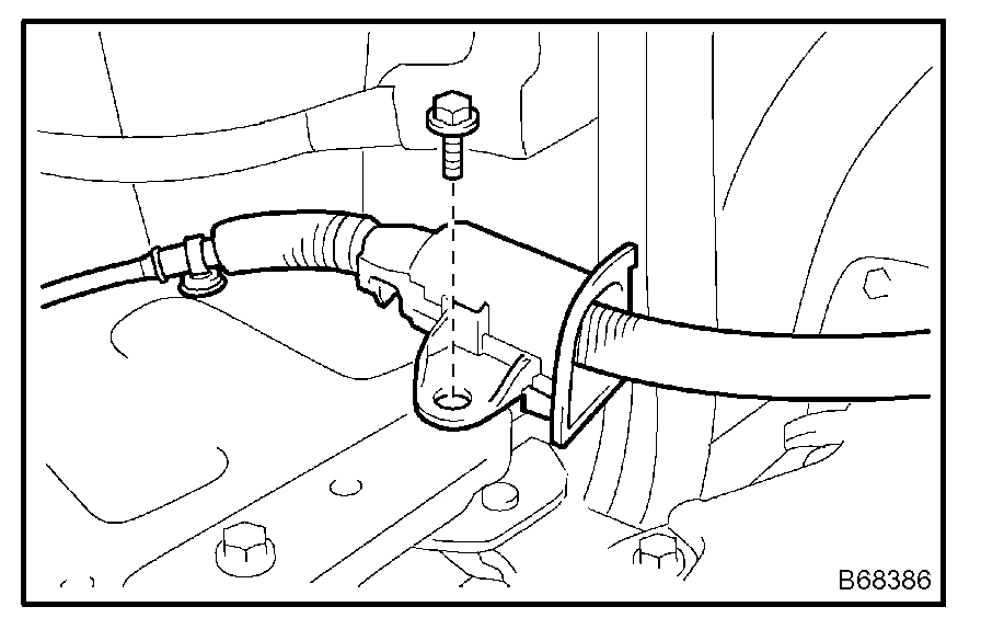
e. Disconnect the 2 connectors from the body side and remove the bolt and wire.
f. Open the quarter glass.
g. Using a screwdriver, disengage the clip and 2 claws, remove the rail end moulding.
HINT: Tape the screwdriver tip before use.
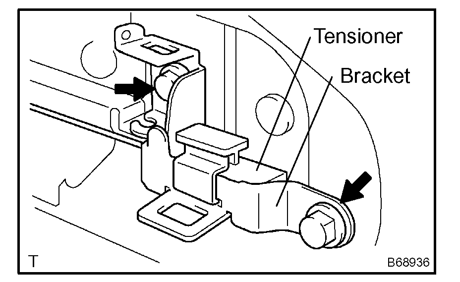
h. Remove the 2 bolts and bracket center No. 2 together with the tensioner (color: white).
i. Remove the tensioner from the bracket center No. 2.
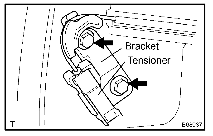
j. Remove the 2 bolts and bracket center No. 1 together with the tensioner (color: black).
k. Remove the tensioner from the bracket center No. 1.
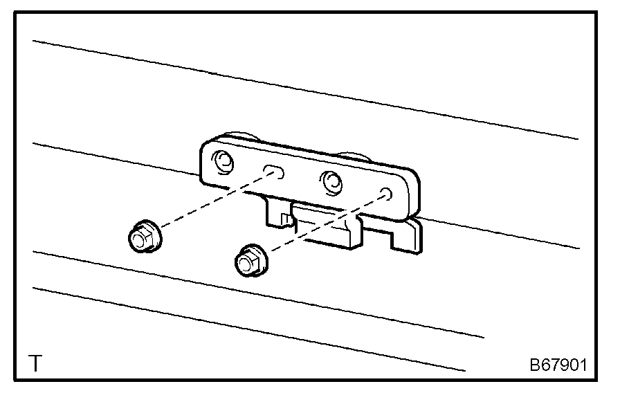
l. Remove the 2 nuts and open stop.
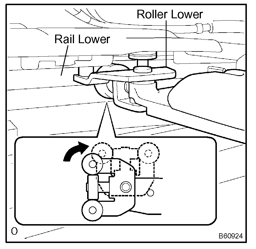
m. Rotate the base of the slide door roller lower in the direction indicated by arrow in the illustration and then remove he roller from the cut area of the lower rail from the body side.
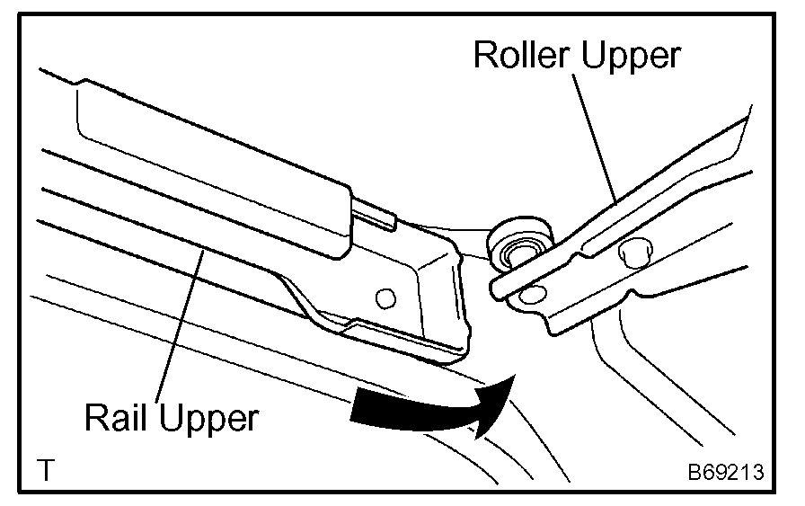
n. Move the slide door rearward and then remove the slide door roller upper from the cut area in the rear part of the slide door rail upper.
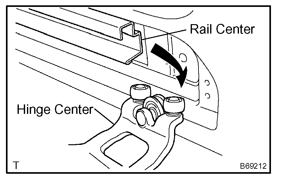
o. Move the slide door further rearward and then remove the slide door hinge center from the rear part of the slide door rail center. Then, remove the slide door.
9. REMOVE SLIDE DOOR RAILS
a. Remove the roof headlining.
b. Remove the 2 bolts, 2 nuts and the rail upper.
c. Remove the 2 screws and rear side rail.
d. Remove the 3 screws and rail center.
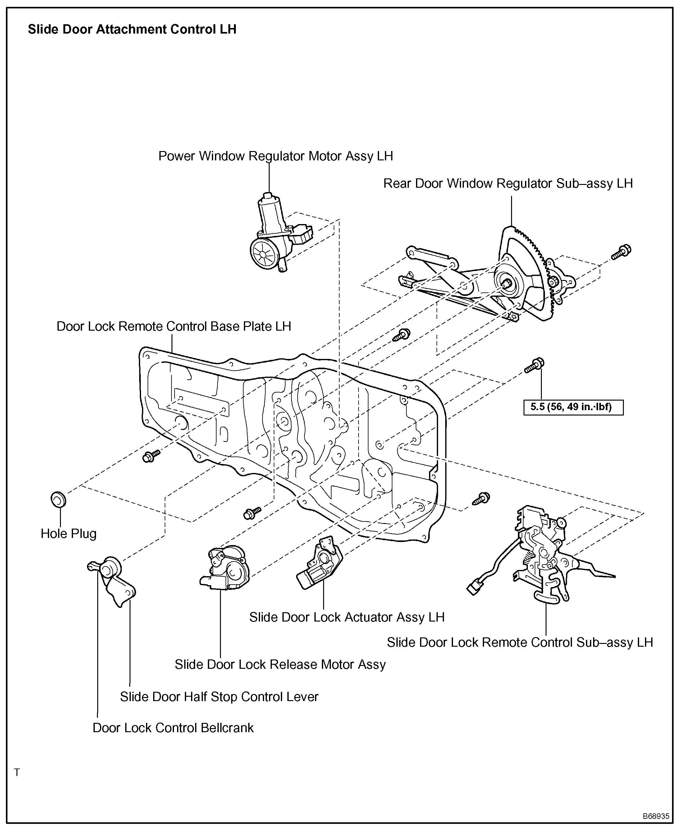
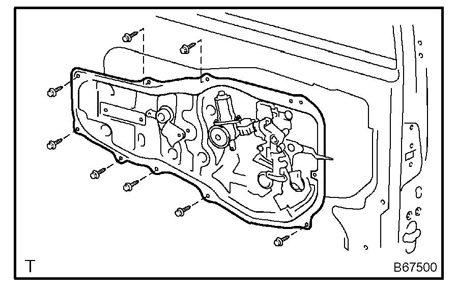
10. REMOVE SLIDE DOOR ATTACHMENT CONTROL LH
a. Remove the 2 screws, bolt and inside handle.
b. Disconnect the connectors from the lock actuator, the power window regulator motor and lock release motor and power slide door lock.
c. Disengage the control wires.
d. Remove the 8 bolts and attachment control.
e. Remove the nut and window frame rear lower.
NOTE: When the nut are removed, the window frame may fall and become deformed.
HINT: Remove the window frame rear lower through the service hole.
f. Remove the control rod.
g. Remove the 3 bolts and lock remote control.
h. Remove the 2 screws and lock actuator.
i. Remove the 2 screws and lock release motor.
j. Remove the 3 screws and power window regulator motor.
k. Remove the half stop control lever and door lock control bellcrank.
l. Remove the 4 bolts and the window regulator.
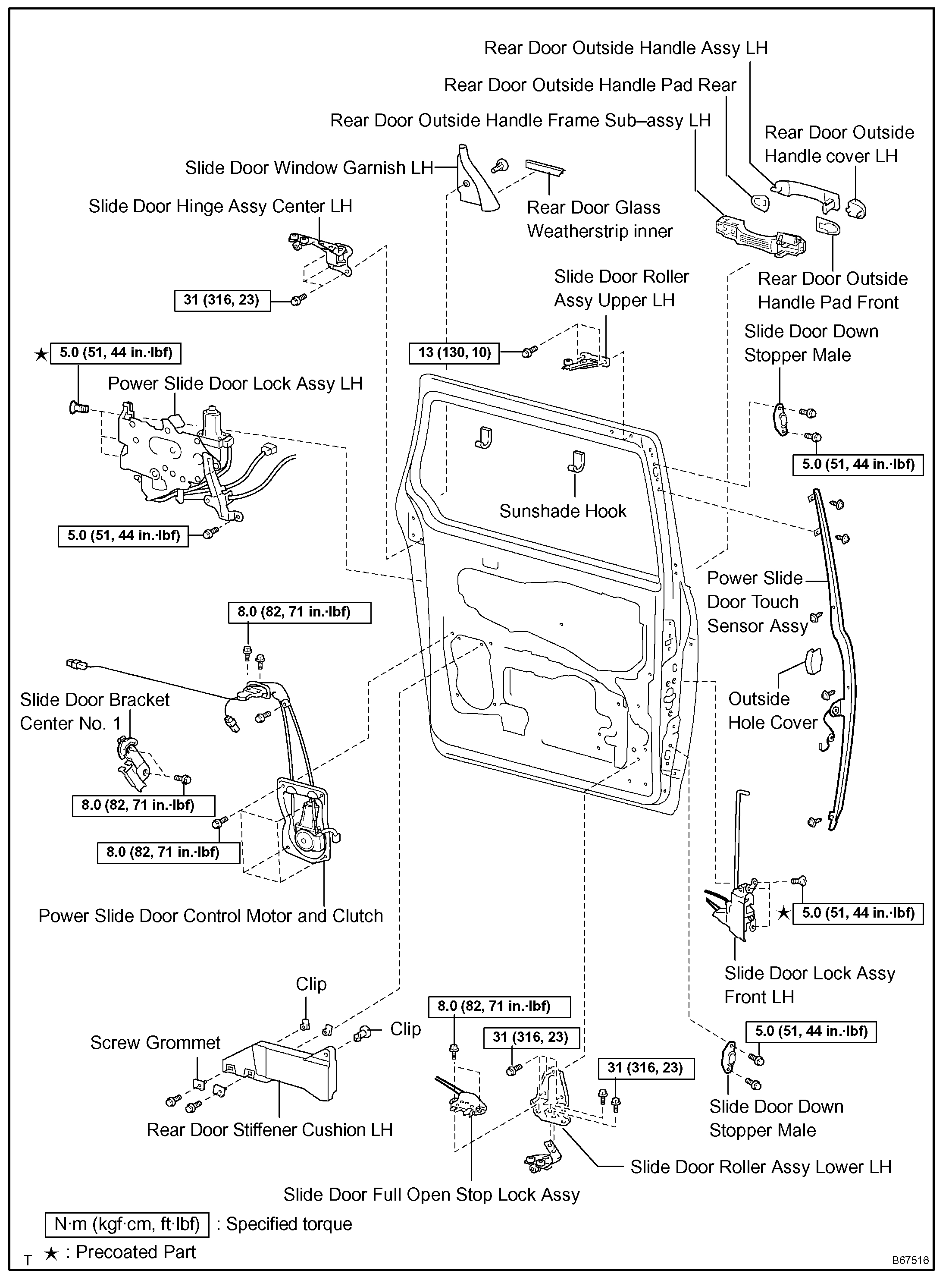
11. REMOVE REAR DOOR OUTSIDE HANDLE COVER LH
a. Remove the outside handle hole cover.
b. Using a torx socket wrench (T30), loosen the screw and remove the outside handle cover with the lock key cylinder installed.
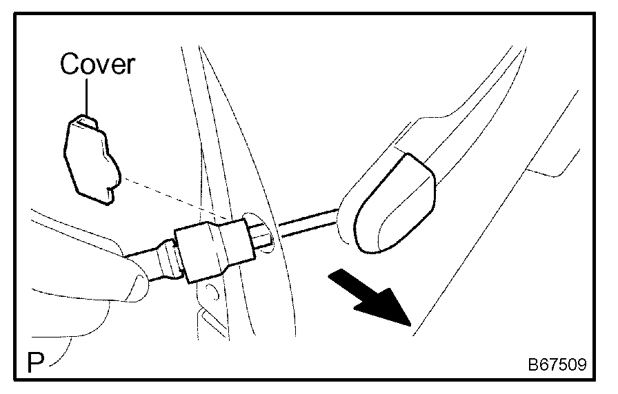
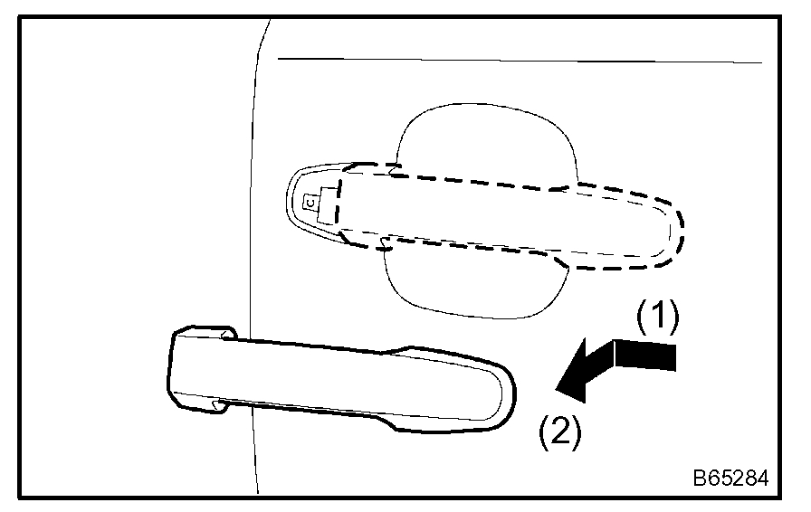
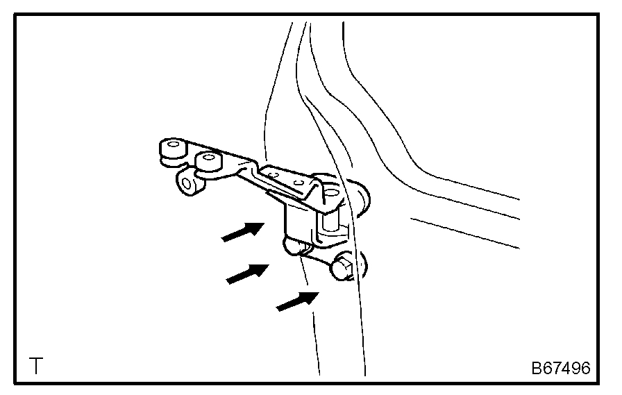
12. REMOVE REAR DOOR OUTSIDE HANDLE ASSEMBLY LH
a. Pushing and pulling the outside handle in the direction indicated by the arrow mark in the illustration, remove the outside handle.
b. Remove the outside handle pads front and rear.
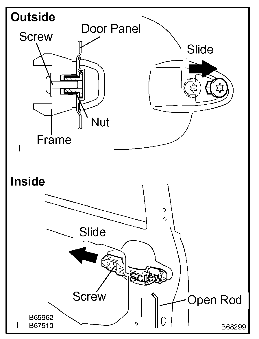
13. REMOVE REAR DOOR OUTSIDE HANDLE FRAME SUB-ASSEMBLY LH
a. Remove the open rod to the outside handle frame.
b. Using a torx socket wrench (T30), loosen the screw.
c. Slide the outside handle frame in the direction indicated by the arrow mark in the illustration and remove it.
HINT: Remove the outside handle frame through the service hole.
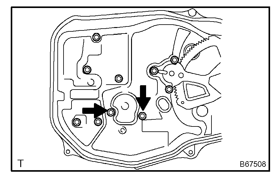
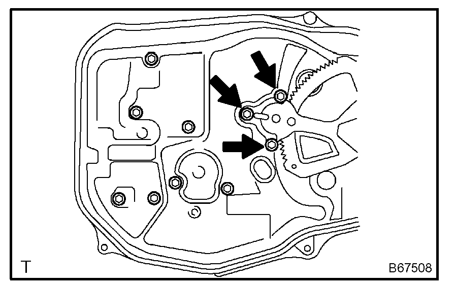
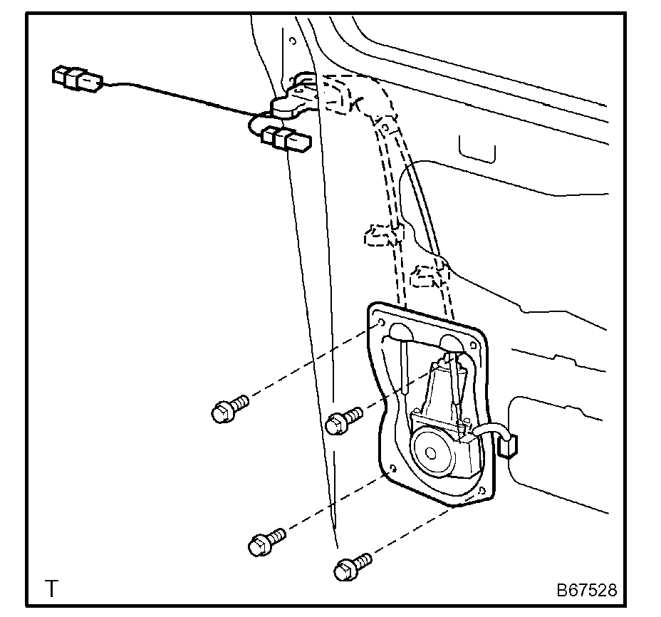
14. REMOVE POWER SLIDE DOOR CONTROL MOTOR AND CLUTCH LH
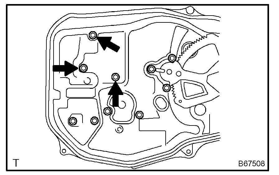
a. Remove the 3 bolts from the upper part of the control motor and clutch.
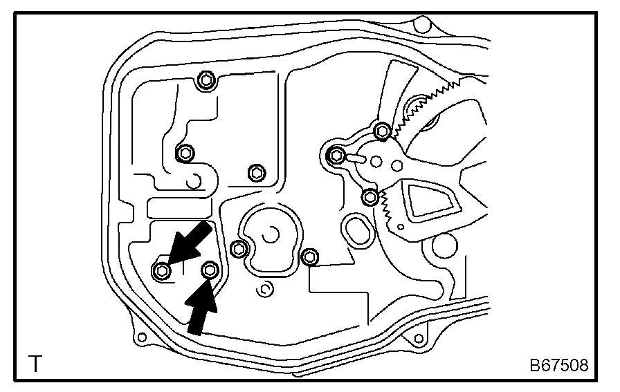
b. Remove the 2 clips and 4 bolts from the lower part of the control motor and clutch.
c. Remove the control motor and clutch.
HINT: Remove the motor and clutch through the service hole.
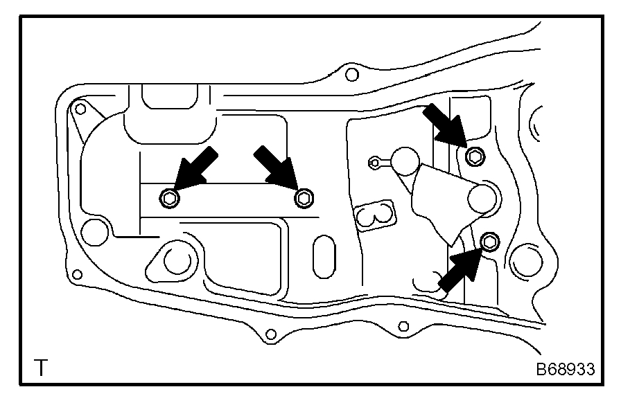
15. REMOVE REAR DOOR STIFFENER CUSHION LH
a. Remove the 2 screws, clip and stiffener cushion.
HINT: Remove the stiffener cushion through the service hole.
b. Remove the 2 grommets and 2 clips.
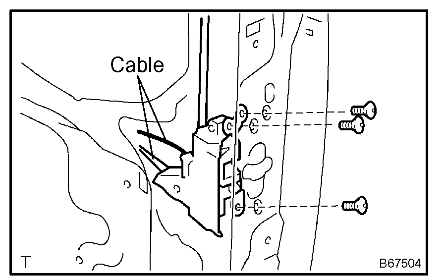
16. REMOVE SLIDE DOOR LOCK ASSEMBLY FRONT LH
a. Disconnect the 2 cables.
b. Using a torx socket wrench (T30), remove the 3 screws and lock.
HINT: Remove the lock front through the service hole.
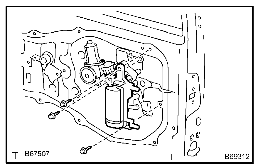
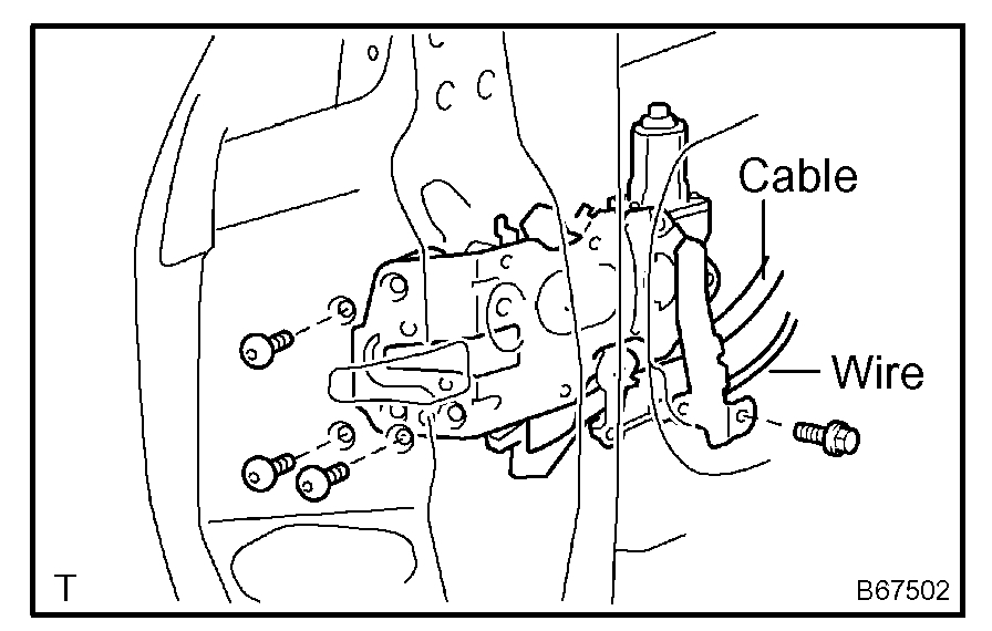
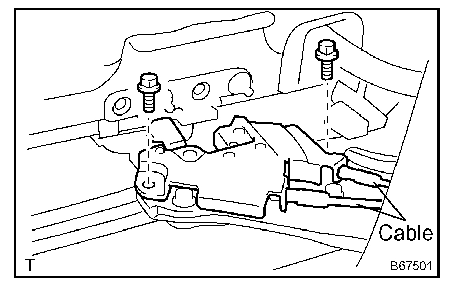
17. REMOVE POWER SLIDE DOOR LOCK ASSEMBLY LH
a. Disconnect the cable and wire.
b. Using a torx socket wrench (T30), remove the 3 screws.
c. Remove the bolt and lock.
HINT: Remove the lock through the service hole.
18. REMOVE REAR DOOR WIRE SUB-ASSEMBLY LH
a. Remove the 2 screws.
b. Using a screwdriver, remove the 2 clips and wire.
HINT: Tape the screwdriver tip before use.
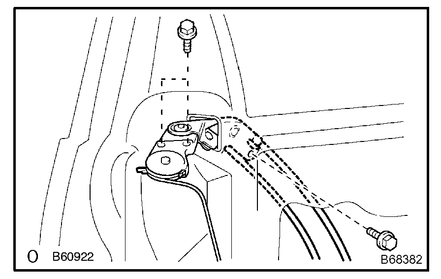
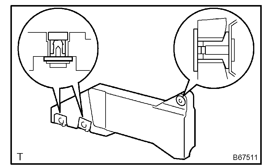
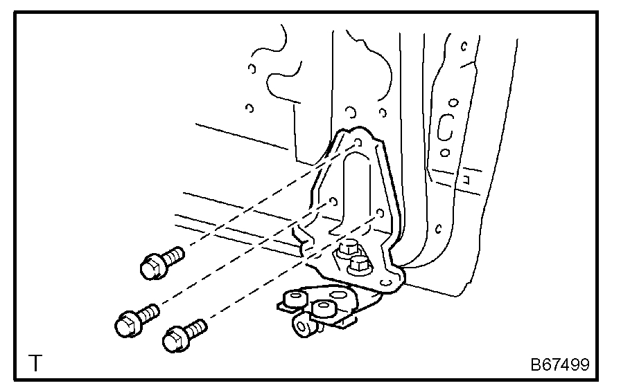
19. REMOVE SLIDE DOOR FULL OPEN STOP LOCK ASSEMBLY LH
a. Disconnect the 2 cables.
b. Remove the 2 bolts and full open stop lock.
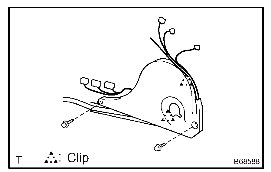
20. REMOVE POWER SLIDE DOOR ECU LH
a. Remove the 2 screws and power slide door ECU with the warning buzzer.
b. Disengage the claw and remove the warning buzzer.
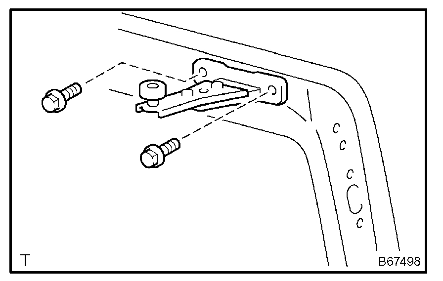
21. REMOVE POWER SLIDE DOOR TOUCH SENSOR LH
a. Disconnect the connector.
b. Remove the 5 screws and touch sensor.
22. REMOVE SLIDE DOOR ROLLER ASSEMBLY LOWER LH
a. Remove the 3 bolts and roller.
23. REMOVE SLIDE DOOR HINGE ASSEMBLY CENTER LH
a. Remove the 3 bolts and hinge.
b. LH side: Remove the cover.
24. REMOVE SLIDE DOOR ROLLER ASSEMBLY UPPER
a. Remove the 2 bolts and roller.
Check out the diagrams (Below). Please let us know what you find.
Images (Click to enlarge)
Apr 12, 2021 at 4:54 PM