Welcome to 2CarPros.
Here are the directions specific to your vehicle regarding the shift solenoids. The directions are broken into two sections, the 1-2 solenoid and 2-3. All attached pics correlate with the directions. Also, to access the solenoids, you have to remove the side cover from the transmission. Those directions are first. Note: The cover removal directions are for cover replacement. You will not be replacing the cover, just following the directions for removal and install.
________________________________________________________
Control Valve Body Cover Replacement
Special Tools
J 36850 - Transjel Lubricant
Removal Procedure
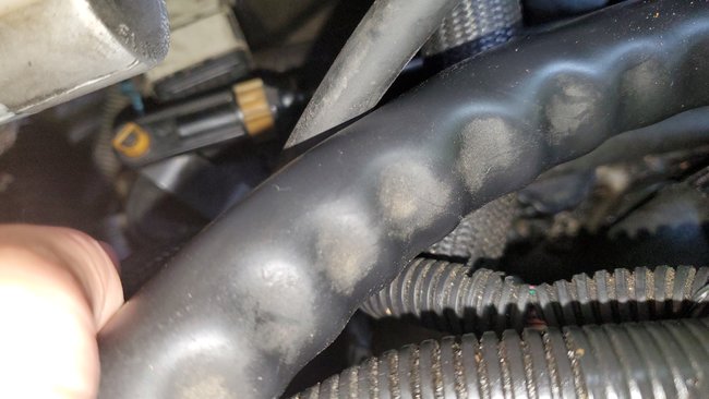
1. Remove the air cleaner housing assembly. Refer to Air Cleaner Assembly Replacement (See: Air Cleaner Housing > Removal and Replacement > Air Cleaner Assembly Replacement).
pic 1
2. Remove the underhood electrical center from the bracket.
3. Remove the underhood electrical center bracket.
pic 2
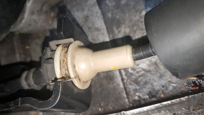
4. Disconnect the shift cable from the PNP switch.
5. Remove the shift cable bracket.
pic 3
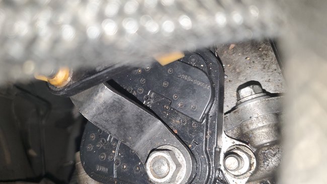
6. Remove the PNP switch lever nut and lever.
pic 4
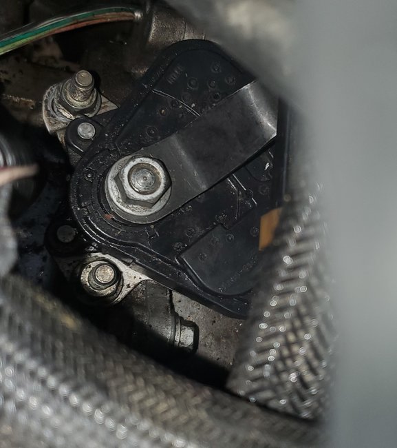
7. Remove the PNP switch. Refer to Park/Neutral Position Switch Replacement (See: Transmission Position Sensor/Switch, A/T > Removal and Replacement > Park/Neutral Position Switch Replacement).
8. Remove the transmission upper side cover bolts.
9. Install the engine support fixture. Refer to Engine Support Fixture (See: Engine > Removal and Replacement > Engine Support Fixture).
10. Raise the vehicle. Refer to Lifting and Jacking the Vehicle (See: Vehicle Lifting > Procedures > Lifting and Jacking the Vehicle).
11. Remove the left front tire and wheel. Refer to Tire and Wheel Removal and Installation (See: Wheels and Tires > Removal and Replacement).
12. Remove the left inner fender liner. Refer to Front Fender Liner Replacement (See: Front Fender Liner > Removal and Replacement).
13. Remove the wheel drive shaft from the transmission. Refer to Wheel Drive Shaft Replacement (See: Axle Shaft Assembly > Removal and Replacement).
14. Remove the power steering gear mounting bolts. Refer to Steering Gear Replacement (See: Steering Gear > Removal and Replacement > Steering Gear Replacement).
15. Remove the frame. Refer to Frame Replacement ().
16. Remove the transmission mount. Refer to Transmission Front Mount Replacement (See: Transmission Mount, A/T > Removal and Replacement > Transmission Front Mount Replacement) or Transmission Rear Mount Replacement (See: Transmission Mount, A/T > Removal and Replacement > Transmission Rear Mount Replacement).
17. Lower the vehicle.
18. Lower the engine with the engine support fixture.
19. Raise the vehicle.
pic 5
20. Remove the 11 transmission side cover bolts (3) or Studs (4) (model dependant).
Caution: Pry on the corner of the case side cover near the locating dowel pins (45), to prevent damage to the sealing surfaces.
21. Remove the transmission side cover (1).
22. Remove the two side cover gaskets (5 and 6) and the side cover to driven support thrust washer (7). They may remain with the side cover. Only replace if necessary.
Installation Procedure
pic 6
1. If the seals were removed, thoroughly clean and dry the side cover seal grooves and the side cover seals.
2. Install the side cover gaskets (5 and 6) into the grooves on the side cover (1).
3. Retain the seals with J 36850 or equivalent.
4. Install the side cover to drive sprocket thrust washer (7) onto the side cover.
5. Retain the thrust washer with J 36850 or equivalent.
pic 7
6. Install the side cover assembly onto the transmission case.
7. Install the 11 side cover bolts (3) or studs (4) (model dependent).
pic 8
8. Refer to the graphic in order to find the correct installation points of the bolts and the stud.
pic 9
Caution: Refer to Fastener Caution (See: Vehicle > Vehicle Damage Warnings > Fastener Caution).
9. Hand start the bolts (3) and tighten the side cover bolts and stud to 28 Nm (22 lb ft).
10. Lower the vehicle.
11. Raise the engine with the engine support fixture.
12. Raise the vehicle.
13. Install the transmission mount. Refer to Transmission Front Mount Replacement (See: Transmission Mount, A/T > Removal and Replacement > Transmission Front Mount Replacement) or Transmission Rear Mount Replacement (See: Transmission Mount, A/T > Removal and Replacement > Transmission Rear Mount Replacement).
14. Install the frame. Refer to Frame Replacement ().
15. Install the power steering gear mounting bolts. Refer to Steering Gear Replacement (See: Steering Gear > Removal and Replacement > Steering Gear Replacement).
16. Install the wheel drive shaft to the transmission. Refer to Wheel Drive Shaft Replacement (See: Axle Shaft Assembly > Removal and Replacement).
17. Connect the left ball joint to the steering knuckle. Refer to Lower Control Arm Ball Joint Replacement (with FE1 Only) (See: Ball Joint > Removal and Replacement > Lower Control Arm Ball Joint Replacement (With FE1 Only)).
18. Install the left inner fender liner. Refer to Front Fender Liner Replacement (See: Front Fender Liner > Removal and Replacement).
19. Install the left front tire and wheel. Refer to Tire and Wheel Removal and Installation (See: Wheels and Tires > Removal and Replacement).
20. Lower the vehicle.
21. Remove the engine support fixture. Refer to Engine Support Fixture (See: Engine > Removal and Replacement > Engine Support Fixture).
pic 10
22. Install the PNP switch. Refer to Park/Neutral Position Switch Replacement (See: Transmission Position Sensor/Switch, A/T > Removal and Replacement > Park/Neutral Position Switch Replacement).
pic 11
23. Install the PNP switch lever and nut and tighten to 35 Nm (26 lb ft).
pic 12
24. Install the shift cable bracket.
25. Connect the shift cable from the PNP switch.
pic 13
26. Install the underhood electrical center bracket.
27. Install the underhood electrical center to the bracket.
28. Install the air cleaner housing assembly. Refer to Air Cleaner Assembly Replacement (See: Air Cleaner Housing > Removal and Replacement > Air Cleaner Assembly Replacement).
29. Fill the transmission. Refer to Transmission Fluid Level and Condition Check (See: Automatic Transmission/Transaxle > Symptom Related Diagnostic Procedures > Transmission Fluid Level and Condition Check) and Fluid Capacity Specifications (See: Fluid - A/T > Capacities).
______________________________________
1-2 SHIFT SOLENOID VALVE REPLACEMENT
1-2 Shift Solenoid Valve Replacement
Removal Procedure
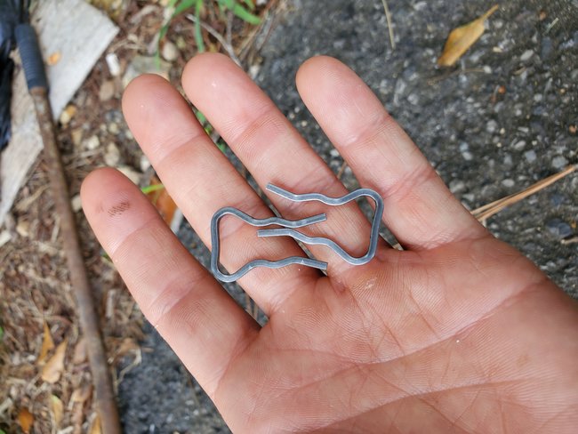
Important: Retainer clips hold in each of the valve line-ups. Use a small screwdriver in order to remove the retainer clips. Be careful not to score the valve body when removing the retainer clips and valves. Before removing the valve line-ups, inspect each valve line-up for freedom of movement.
See pic 14
1. Remove the transmission side cover. Refer to Control Valve Body Cover Replacement (See: Valve Body, A/T > Removal and Replacement > Control Valve Body Cover Replacement).
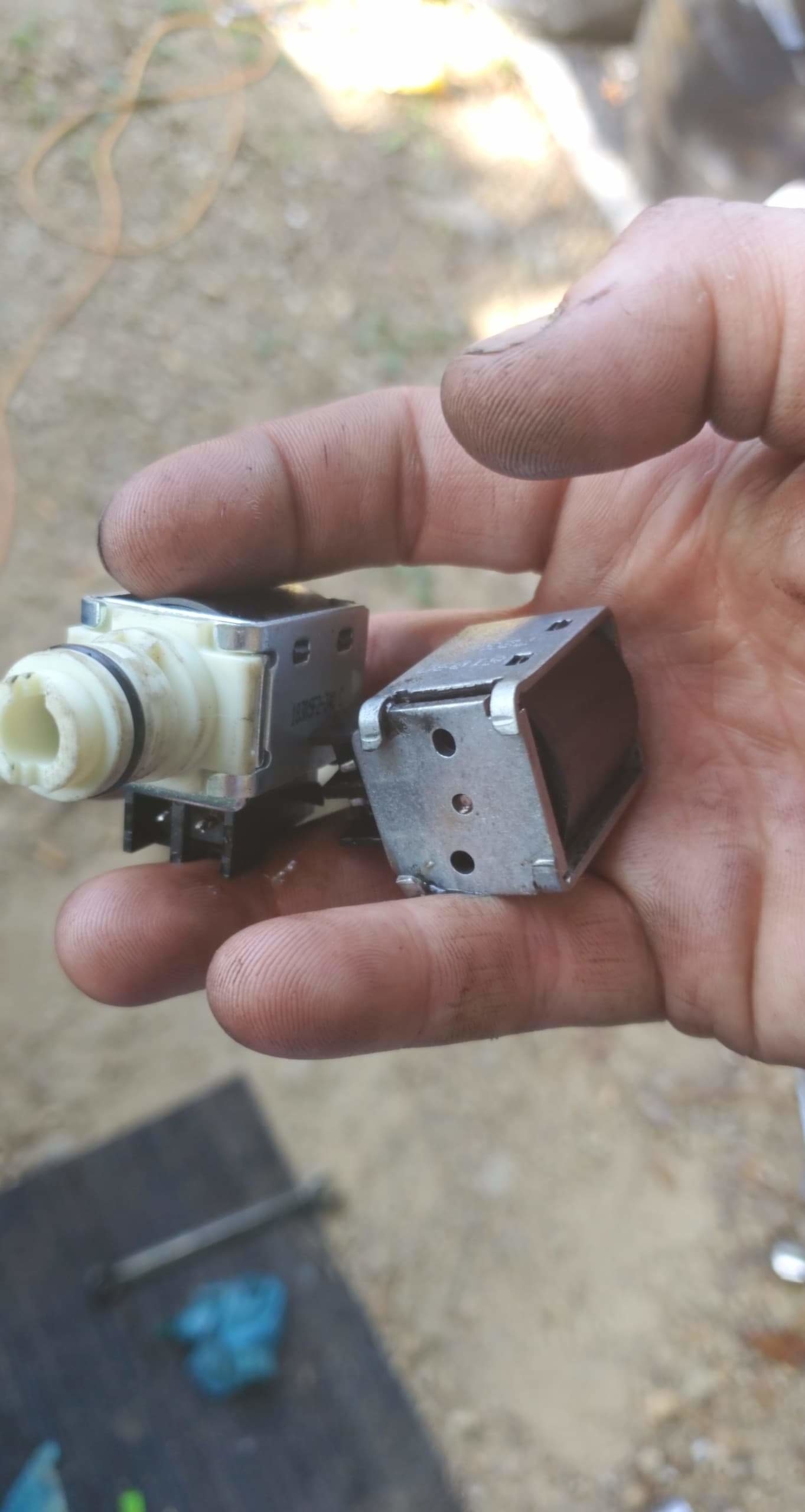
2. Remove the 1-2 shift solenoid retainer clip (304), the 1-2 shift solenoid (305) with O-ring (303), the 1-2 shift valve (302), and the 1-2 shift valve spring (301).
Installation Procedure
See Pic 15
1. Install the 1-2 shift valve spring (301), the 1-2 shift valve (302), the 1-2 shift solenoid (305) with O-ring (303) and the 1-2 shift solenoid retainer clip (304).
2. Install the transmission side cover. Refer to Control Valve Body Cover Replacement (See: Valve Body, A/T > Removal and Replacement > Control Valve Body Cover Replacement).
Important: It is recommended that transmission adaptive pressure (TAP) information be reset.
Resetting the TAP values using a scan tool will erase all learned values in all cells. As a result, The ECM, PCM or TCM will need to relearn TAP values. Transmission performance may be affected as new TAP values are learned.
3. Reset the TAP values. Refer to Transmission Adaptive Functions (See: Automatic Transmission/Transaxle > Components > Transmission Adaptive Functions).
______________________________________________________________________
2-3 SHIFT SOLENOID VALVE REPLACEMENT
2-3 Shift Solenoid Valve Replacement
Removal Procedure
Important: Retainer clips hold in each of the valve line-ups. Use a small screwdriver in order to remove the retainer clips. Be careful not to score the valve body when removing the retainer clips and valves. Before removing the valve line-ups, inspect each valve line-up for freedom of movement.
pic 16
1. Remove the transmission side cover. Refer to Control Valve Body Cover Replacement (See: Valve Body, A/T > Removal and Replacement > Control Valve Body Cover Replacement).
2. Remove the 2-3 shift solenoid retainer clip (304), the 2-3 shift solenoid (305) with O-ring (303), the 2-3 shift valve (307), and the 2-3 shift valve spring (306).
Installation Procedure
pic 17
1. Install the 2-3 shift valve spring (306), the 2-3 shift valve (307), the 2-3 shift solenoid (305) with O-ring (303) and the 2-3 shift solenoid retainer clip (304).
2. Install the transmission side cover. Refer to Control Valve Body Cover Replacement (See: Valve Body, A/T > Removal and Replacement > Control Valve Body Cover Replacement).
Important: It is recommended that transmission adaptive pressure (TAP) information be reset.
Resetting the TAP values using a scan tool will erase all learned values in all cells. As a result, The ECM, PCM or TCM will need to relearn TAP values. Transmission performance may be affected as new TAP values are learned.
3. Reset the TAP values. Refer to Transmission Adaptive Functions (See: Automatic Transmission/Transaxle > Components > Transmission Adaptive Functions).
______________________________
Let me know if this is what you needed or if you have other questions.
Take care,
Joe
Images (Click to enlarge)
Jul 3, 2019 at 9:03 PM