Hi,
I believe it rotates clockwise. Here are the directions for camshaft timing adjustment for both banks. The first is the left. The attached pictures correlate with the directions.
____________________________________________________
2004 BMW X5 (E53) V8-4.4L (N62)
Adjusting Camshaft Timing on Left Side
Vehicle Engine, Cooling and Exhaust Engine Camshaft, Lifters and Push Rods Adjustments Adjusting Camshaft Timing on Left Side
ADJUSTING CAMSHAFT TIMING ON LEFT SIDE
Adjusting Camshaft Timing On Left Side (N62)
Special Tools Required:
^ 11 9 190
^ 11 9 460
^ 11 9 461
^ 11 9 462
^ 11 9 463
(Cylinder Bank 5 to 8)
The preliminary tasks are described in the section "Checking camshaft timing on left side".
Remove left timing case cover.
pic 1
Note:
When slackening screws, grip camshafts at hexagon head.
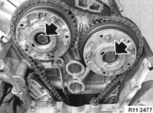
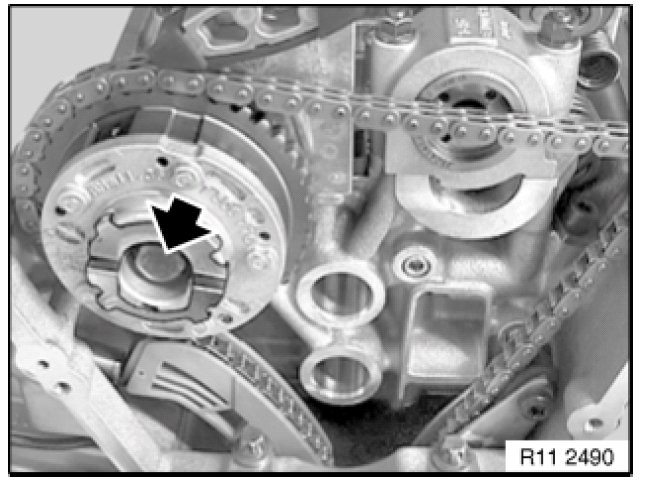
Slacken screws of exhaust and inlet adjustment unit.
pic 2
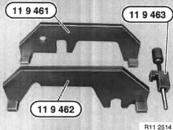
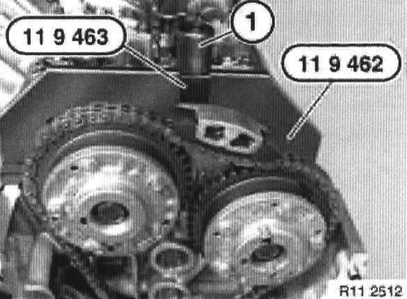
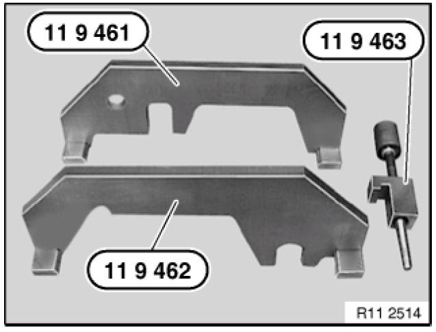
Get special tool kit 11 9 460 ready for securing camshafts.
Note:
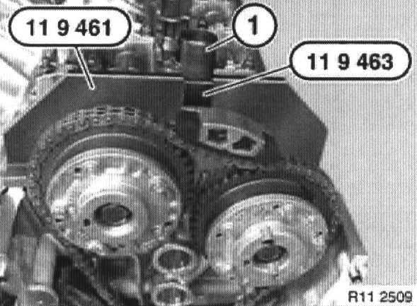
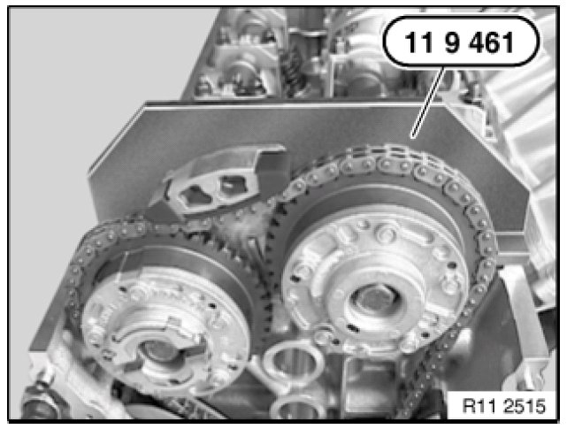
Special tool 11 9 461 for securing inlet camshaft.
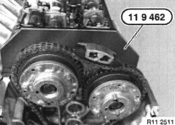
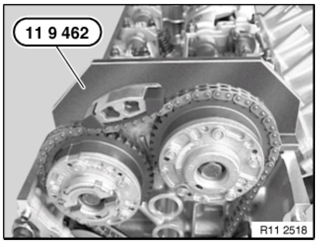
Special tool 11 9 462 for securing exhaust camshaft.
Special tool 11 9 463 (holder with screw).
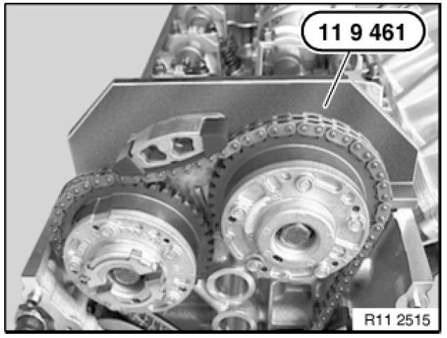
pic 3
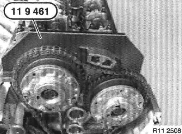
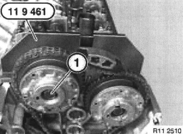
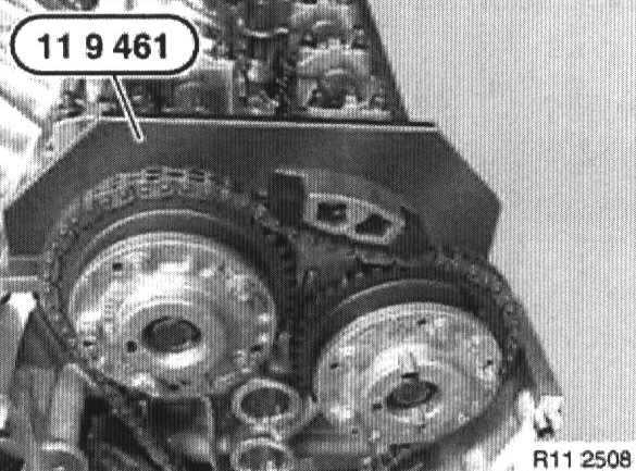
Place special tool 11 9 461 on inlet camshaft and align inlet camshaft so that special tool 11 9 461 rests without a gap on cylinder head.
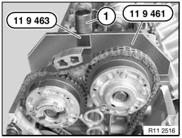
pic 4
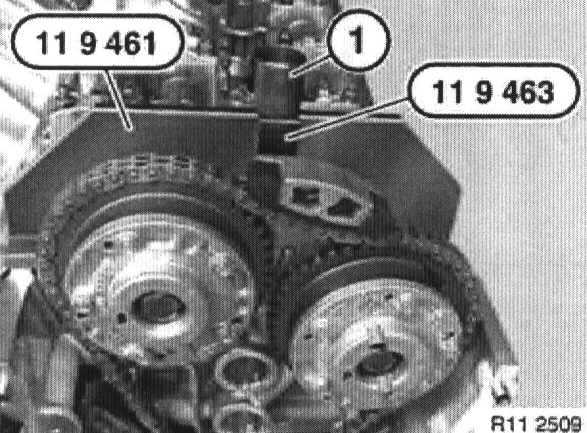
Fit special tool 11 9 463, secure screw (1) in thread for oil line and tighten down by hand.
pic 5
Note:
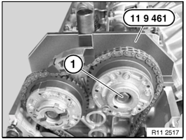
When tightening down screw (1), grip camshaft at hexagon head.
Tighten down screw (1) of inlet adjustment unit.
Adjustment unit to exhaust or inlet camshaft
M10 x 1 .................... 90 Nm
pic 6
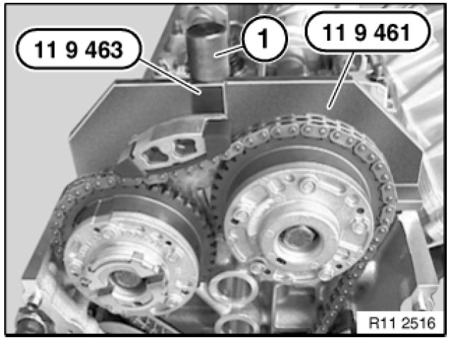
Release screw (1), remove special tools 11 9 463 and 11 9 461 from inlet camshaft.
pic 7
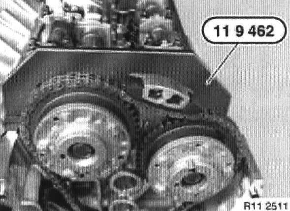
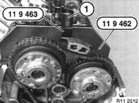
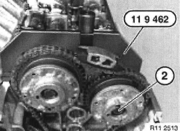
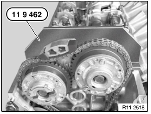
Place special tool 11 9 462 on exhaust camshaft and align exhaust camshaft so that special tool 11 9 462 rests without a gap on cylinder head.
pic 8
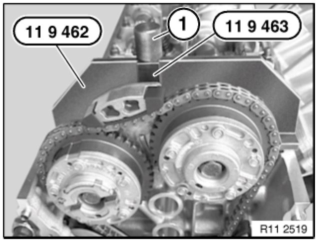
Fit special tool 11 9 463, secure screw (1 ) in thread for oil line and tighten down by hand.
pic 9
Note:
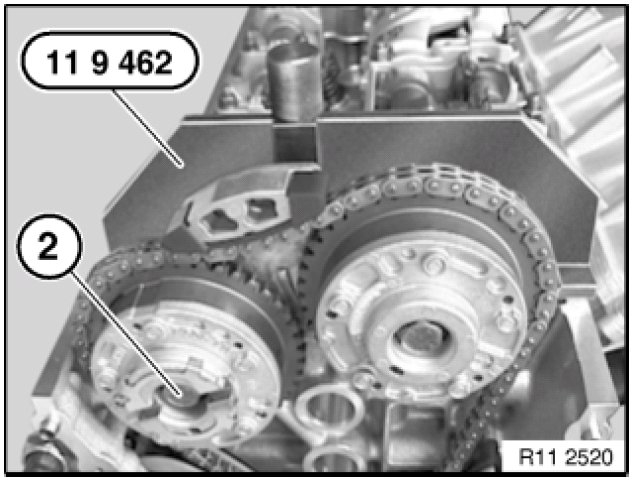
When tightening down screw (2), grip camshaft at hexagon head.
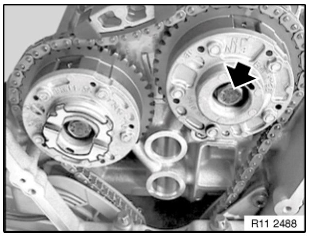
Tighten down screw (2) of exhaust adjustment unit.
Adjustment unit to exhaust or inlet camshaft
M10 x 1 .................... 90 Nm
pic 10
Release screw (1), remove special tools 11 9 463 and 11 9 462 from exhaust camshaft.
pic 11
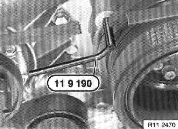
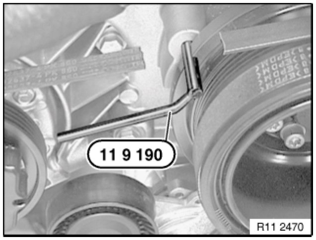
Remove special tool 11 9 190
Crank engine at central bolt twice in direction of rotation until engine returns to firing TDC position of 1st cylinder.
Secure vibration damper with special tool 11 9 190 in firing TDC position of 1st cylinder.
pic 12
Place special tool 11 9 461 on inlet camshaft and check timing.
Note:
The timing is correctly adjusted when special tool 11 9 461 rests flat on the cylinder head or protrudes by up to 0.5 mm to the exhaust side.
Remove special tool 11 9 461 from inlet camshaft.
pic 13
Place special tool 11 9 462 on exhaust camshaft and check timing.
Note: The timing is correctly adjusted when special tool 11 9 462 rests flat on the cylinder head or protrudes by up to 0.5 mm to the exhaust side.
Remove all special tools.
Assemble engine.
________________________________________________
Right bank:
Installation:
Installation of inlet and exhaust adjustment units is described separately from removal.
pic 14
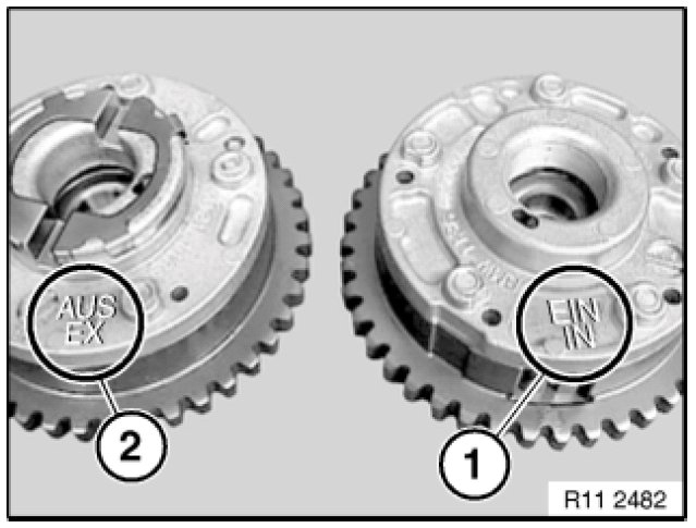
Important!
Danger of mix-up:
Inlet and exhaust adjustment units are different.
Mixing up the inlet and exhaust adjustment units will cause damage to the engine.
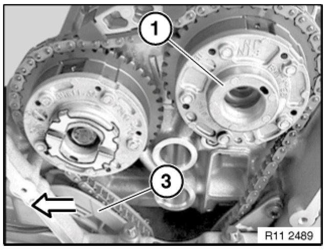
1. Inlet adjustment unit ( 1 ) is marked with EIN and IN.
2. Exhaust adjustment unit ( 2 ) is marked with AUS and EX.
pic 15
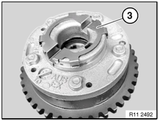
Note:
The exhaust adjustment unit on cylinder bank 1 to 4 has a metal clip ( 3 ) for driving the vacuum pump.
pic 16
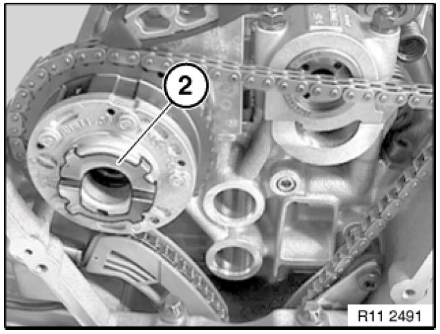
Note:
Position of exhaust adjustment unit ( 2 ) to timing chain can be freely selected.
Pull timing chain up.
Feed exhaust adjustment unit ( 2 ) into timing chain and fit onto inlet camshaft.
pic 17
Replace screw.
Install screw on exhaust adjustment unit.
Tighten screw without play and then slacken off again by half a turn.
Note:
Position of inlet adjustment unit ( 1 ) to timing chain can be freely selected.
Pull timing chain up.
Feed inlet adjustment unit ( 1 ) into timing chain.
pic 18
Press tensioner rail ( 3 ) back and fit inlet adjustment unit ( 1 ) onto exhaust camshaft.
Note:
If tensioner rail ( 3 ) cannot be pressed back far enough to enable fitting of inlet adjustment unit ( 1 ):
Slacken off chain tensioner by approx. three turns
Fit inlet adjustment unit ( 1 ).
Replace and insert screw on inlet adjustment unit ( 1 ).
Tighten down chain tensioner.
Tightening torque of chain tensioner: 65 Nm.
pic 19
Tighten screw on inlet adjustment unit without play and then slacken off again by a half a turn.
pic 20
Get special tool kit 11 9 460 ready for securing camshafts.
Note:
Special tool 11 9 461 for securing inlet camshaft.
Special tool 11 9 462 for securing exhaust camshaft.
Special tool 11 9 463 ( holder with screw ).
pic 21
Place special tool 11 9 461 on inlet camshaft and align inlet camshaft so that special tool 11 9 461 rests without a gap on cylinder head.
pic 22
Fit special tool 11 9 463, secure screw ( 1 ) in thread for oil line and tighten down by hand.
pic 23
Important!
Make sure screws of inlet and exhaust adjustment units have been slackened by a half a turn.
Crank engine at central bolt from 45° before TDC position in direction of rotation to firing TDC position of 1st cylinder.
Secure vibration damper with special tool 11 9 190 in firing TDC position of 1st cylinder.
pic 24
Note:
When tightening down screw ( 1 ), grip camshaft at hexagon head.
Tighten down screw ( 1 ) of inlet adjustment unit.
Tightening torque of inlet adjustment unit: 80 Nm.
pic 25
Release screw ( 1 ) and remove special tools 11 9 463 / 11 9 461 from inlet camshaft.
pic 26
Place special tool 11 9 462 on exhaust camshaft and align exhaust camshaft so that special tool 11 9 462 rests without a gap on cylinder head.
pic 27
Fit special tool 11 9 463, secure screw ( 1 ) in thread for oil line and tighten down by hand.
pic 28
Note:
When tightening down screw ( 2 ), grip camshaft at hexagon head.
Tighten down screw ( 2 ) of exhaust adjustment unit.
Tightening torque of exhaust adjustment unit: 80 Nm.
pic 29
Release screw ( 1 ) and remove special tools 11 9 463 / 11 9 462 from exhaust camshaft.
pic 30
Remove special tool 11 9 190.
Crank engine at central bolt twice in direction of rotation until engine returns to firing TDC position of 1st cylinder.
Secure vibration damper with special tool 11 9 190 in firing TDC position of 1st cylinder.
pic 31
Place special tool 11 9 461 on inlet camshaft and check timing.
Note:
The timing is correctly adjusted when special tool 11 9 461 rests flat on the cylinder head or protrudes by up to 0.5 mm to the exhaust side.
pic 32
Place special tool 11 9 462 on exhaust camshaft and check timing.
Note:
The timing is correctly adjusted when special tool 11 9 462 rests flat on the cylinder head or protrudes by up to 0.5 mm to the exhaust side.
Remove all special tools.
pic 33
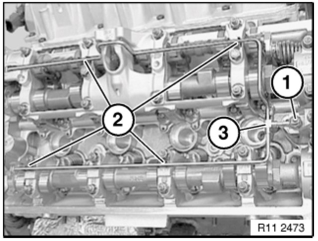
Important!
Screw ( 1 ) is a special screw and must be replaced with a normal M8 screw.
Clip oil line ( 3 ) into retainers ( 2 ).
Insert screw ( 1 ) and tighten down.
Assemble engine.
_____________________________________________________
Let me know if this helps.
Take care,
Joe
Images (Click to enlarge)
Dec 4, 2019 at 8:14 PM