Replaced head gaskets now check engine light and codes P0107, P0641 and P0452

Tiny
BRITNEYS
  • MEMBER
  • 2008 CHEVROLET EQUINOX
  • 3.4L
  • V6
  • 2WD
  • AUTOMATIC
  • 130,000 MILES
Bought the vehicle listed above in February. Heat went out took it back to where I bought it and since then it has had a new radiator, engine coolant sensor, water pump, beater core, thermostat and as of yesterday head gaskets. Took it to a Chevrolet dealer and they found exhaust fumes in coolant. Start the car and check engine light is on and says reduced engine power. It does not drive any different than it did before but is throwing codes p0107, p0641, and p0452.
Thursday, April 5th, 2018 AT 5:59 PM

3 Replies

Tiny
ASEMASTER6371
  • MECHANIC
  • 52,797 POSTS
Good morning.

The 107 is for the MAP sensor. A description is below for the code. The most common issue is the connector. There needs to be a five volt reference signal to this sensor. If it is missing, this code will set.

Roy

Circuit/System Description:

The MAP sensor has a 5-volt reference circuit, a low reference circuit, and a signal circuit. The engine control module (ECM) supplies 5 volts to the MAP sensor on a 5-volt reference circuit, and provides a ground on a low reference circuit. The MAP sensor provides a voltage signal to the ECM on a signal circuit relative to the intake manifold pressure changes.

Conditions for Running the DTC.

P0107
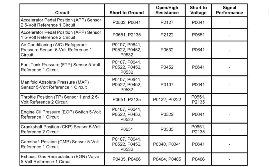
* DTCs P0120, P0121, P0122, P0123, P0220, P0222, P0223, P0641, P0651 or P2135 are not set.
* The engine is running greater than or equal to 400 RPM.
* The throttle position is greater than or equal to 0 percent when the engine speed is less than or equal to 1,000 RPM.
OR
* The throttle position is greater than or equal to 12.5 percent when the engine speed is greater than 1,000 RPM.
* The DTC runs continuously when the above conditions are met.

P0108
* The engine has been running for a length of time that is determined by the start-up coolant temperature. The length of time ranges from 5.5 minutes at less than -30°C (-22°F) to 10 seconds at more than +30°C (+86°F).
* DTCs P0120, P0121, P0122, P0123, P0220, P0222, P0223, or P2135 are not set.
* The throttle position is less than or equal to one percent when the engine speed is less than or equal to 1,200 RPM.
OR
* The throttle position is less than or equal to 20 percent when the engine speed is greater than 1,200 RPM.
* The DTC runs continuously when the above conditions are met.

Conditions for Setting the DTC

P0107

The ECM detects that the MAP sensor voltage is less than 0.05 volt for greater than 5 seconds.

P0108

The ECM detects that the MAP sensor voltage is more than 4.9 volts for greater than 5 seconds.

Action Taken When the DTC Sets

DTC P0107 and P0108 are Type B DTCs.

Conditions for Clearing the DTC

DTC P0107 and P0108 are Type B DTCs.

Special Tools

* J 23738-A Mityvac
* J 35555 Metal Mityvac

Circuit/System Verification

1. Verify that the following DTCs are not set: P0641 or P0651.

If any of the DTCs are set, refer to DTC P0641 or P0651. See: A L L Diagnostic Trouble Codes ( DTC ) > P Code Charts > P0641

2. Ignition ON, observe the MAP Sensor parameter. The reading should be between 0.05-4.9 volts.
3. Operate the vehicle within the Conditions for Running the DTC. You may also operate the vehicle within the conditions that you observed from the Freeze Frame/Failure Records data.

Circuit/System Testing

1. Ignition OFF, disconnect the harness connector at the MAP sensor.
2. Ignition OFF for 90 seconds, test for less than 5 ohms between the low reference circuit terminal 2 and ground.

If greater than the specified range, test the low reference circuit for an open/high resistance. If the circuit tests normal, replace the ECM.

3. Ignition ON, test for 4.8-5.2 volts between the 5-volt reference circuit terminal 1 and ground.

If less than the specified range, test the 5-volt reference circuit for a short to ground or an open/high resistance. If the circuit tests normal, replace the ECM.
If greater than the specified range, test the 5-volt reference circuit for a short to voltage. If the circuit tests normal, replace the ECM.

4. Verify the scan tool MAP Sensor parameter is less than 12 kPa.

If greater than the specified range, test the signal circuit terminal 3 for a short to voltage. If the circuit tests normal, replace the ECM.

5. Install a 3A fused jumper wire between the signal circuit terminal 3 and the 5-volt reference circuit terminal 1. Verify the scan tool MAP Sensor parameter is greater than 102 kPa.

If less than the specified range, test the signal circuit for short to ground or an open/high resistance. If the circuit tests normal, replace the ECM.

6. If all circuits test normal, test or replace the MAP sensor.

Component Testing

Important: You must perform the Circuit/System Testing before proceeding with the Component Testing.

1. Ignition OFF, remove the MAP sensor.
2. Install a 3A fused jumper wire between the 5-volt reference circuit terminal 1 and the corresponding terminal of the MAP sensor.
3. Install a jumper wire between the low reference circuit terminal 2 of the MAP sensor and ground.
4. Install a jumper wire at terminal 3 of the MAP sensor.
5. Connect a DMM between the jumper wire from terminal 3 of the MAP sensor and ground.
6. Ignition ON, with the J 23738-A or J 35555 slowly apply vacuum to the sensor while observing the voltage on the DMM. The voltage should vary between 0-5.2 volts, without any spikes or dropouts.

If the voltage reading is erratic, replace the MAP sensor.

Repair Instructions

Perform the Diagnostic Repair Verification after completing the diagnostic procedure. See: A L L Diagnostic Trouble Codes ( DTC ) > Verification Tests

* Manifold Absolute Pressure Sensor Replacement.
Was this
answer
helpful?
Yes
No
Friday, April 6th, 2018 AT 4:24 AM
Tiny
ASEMASTER6371
  • MECHANIC
  • 52,797 POSTS
Okay, 641 is also a five volt reference as well. The sensors are listed that need this voltage. Check them to see if any have reference. This could be a failing PCM.

Roy

Circuit/System Description

The engine control module (ECM) has a 5-volt reference buss for each 5-volt reference circuit. The circuits are called 5-volt reference 1 and 5-volt reference 2. Each bus provides a 5-volt reference for more than one sensor. A fault condition on one 5-volt reference circuit will affect the other 5-volt reference circuits connected to that reference bus. The ECM monitors the voltage on the 5-volt reference busses.

The 5-volt reference 1 bus provides 5 volts to the following sensors:

* The exhaust gas recirculation (EGR) valve
* The manifold absolute pressure (MAP) sensor
* The fuel tank pressure (FTP) sensor
* The accelerator pedal position (APP) sensor 2
* The engine oil pressure (EOP) switch
* The air conditioning (A/C) refrigerant pressure sensor
* The camshaft position (CMP) sensor

The 5-volt reference 2 bus provides 5 volts to the following sensors:

* The APP sensor 1
* The throttle position (TP) sensor 1 and 2
* The crankshaft position (CKP) sensor

Conditions for Running the DTC

* DTCs P0601, P0602, P0603, P0604, P0605, P0606, P0607, P060D, P062F and P2610 are not set.
* The ignition is ON.
* The ignition voltage is greater than 5.23 volts.
* The DTCs run continuously when the above conditions are met.

Conditions for Setting the DTC

The ECM detects a voltage out of range condition on the 5-volt reference 1 or 2 bus for greater than 0.5 second.

Action Taken When the DTC Sets

DTC P0641 and P0651 are Type A DTCs.

Conditions for Clearing the MIL/DTC

DTC P0641 and P0651 are Type A DTCs.

Diagnostic Aids

It may be possible to locate the fault by disconnecting one component at a time from the affected 5-volt reference circuit while viewing the 5-Volt Reference circuit status parameter on the scan tool. The scan tool parameter will change from Fault to OK when the source of the fault is disconnected.

If all 5-volt reference components have been disconnected and a fault is still indicated, the fault may exist in the wiring harness.

Circuit/System Verification

1. Observe the scan tool 5-volt reference 1 circuit status and the 5-volt reference 2 circuit status parameters. Verify the parameters display OK.
2. Ignition ON, observe the DTC information with a scan tool. DTCs P0641 and P0651 should not set on this ignition cycle.
3. Operate the vehicle within the Conditions for Running the DTC. You may also operate the vehicle within the conditions that you observed from the Freeze Frame/Failure Records data.

Circuit/System Testing

Important: A short to voltage on the signal circuit of certain components may cause this DTC to set.

1. Ignition OFF, disconnect the harness connector of all appropriate sensors for the applicable DTC.
2. Ignition ON, measure for 4.8-5.2 volts between one of the 5-volt reference circuits and ground.

If the voltage is less than the specified value, test for a short to ground on all the 5-volt reference circuits. If all circuits test normal, replace the ECM.
If the voltage is greater than the specified value, test for a short to voltage on all the 5-volt reference circuits for each component associated with the appropriate 5-volt reference circuit. If all circuits test normal, replace the ECM.

3. Connect each component associated with the 5-volt reference circuit, one at a time, while monitoring the voltage. Verify he voltage remains between 4.8-5.2 volts.

If the voltage display is not within the specified range when a component is connected, test the signal circuit for a short to voltage. If the circuit tests normal, replace the component.

Repair Instructions

Perform the Diagnostic Repair Verification after completing the diagnostic procedure. See: A L L Diagnostic Trouble Codes ( DTC ) > Verification Tests

* Accelerator Pedal Position Sensor Replacement
* Air Conditioning (A/C) Refrigerant Pressure Sensor Replacement (LNJ) Air Conditioning (A/C) Refrigerant Pressure Sensor Replacement (LY7)
* Camshaft Position Sensor Replacement
* Crankshaft Position Sensor Replacement
* Engine Oil Pressure Sensor and/or Switch Replacement
* Exhaust Gas Recirculation Valve Replacement
* Fuel Tank Pressure Sensor Replacement
* Manifold Absolute Pressure Sensor Replacement
* Throttle Body Assembly Replacement.
Was this
answer
helpful?
Yes
No
Friday, April 6th, 2018 AT 4:27 AM
Tiny
ASEMASTER6371
  • MECHANIC
  • 52,797 POSTS
Okay, the 452 is the same. It is missing the five volt reference.

This voltage is provided by the PCM. There is no fuse for this as well.

Roy
Was this
answer
helpful?
Yes
No
Friday, April 6th, 2018 AT 4:29 AM

Please login or register to post a reply.

Sponsored links