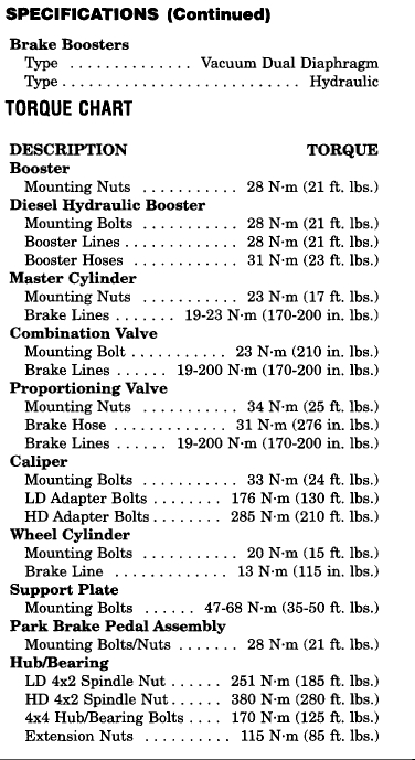
Hi and thanks for using 2CarPros. Com. The first set of directions are for the front brakes. The first five pictures correlate with the front brake replacement. Picture six is the torque specifications for all brake components.
2000 Dodge or Ram Truck RAM 3500 Truck 2WD L6-5.9L DSL Turbo VIN 6
Vehicle � Brakes and Traction Control � Disc Brake System � Brake Pad � Service and Repair
SERVICE AND REPAIR
If brake shoes are to be replaced, remove 1/4 of the fluid from master cylinder with suction gun.
REMOVAL
Raise and support vehicle.
Remove front wheel and tire assemblies.
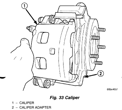
Remove caliper mounting bolts.
Remove caliper by tilting the top up and off the caliper adapter.
NOTE: Do not allow brake hose to support caliper assembly.
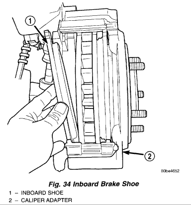
Remove inboard brake shoe from the caliper adapter.
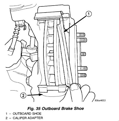
Remove outboard brake shoe from caliper adapter).
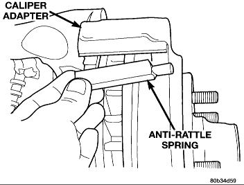
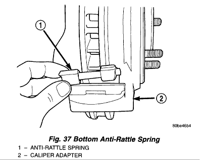
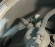
Top Anti-Rattle Spring
Remove the anti-rattle springs from the caliper adapter.
NOTE: Anti-rattle springs are not interchangeable.
INSTALLATION
Bottom pistons in caliper bore with C-clamp. Place an old brake shoe between a C-clamp and caliper piston.
Clean caliper mounting adapter and anti-rattle springs.
Lubricate anti-rattle springs with Mopar brake grease.
Install anti-rattle springs.
NOTE: Anti-rattle springs are not interchangeable.
Install inboard brake shoe in adapter.
Install outboard brake shoe in adapter.
Tilt the bottom of the caliper over rotor and under adapter. Then push the top of the caliper down onto the adapter.
Install caliper mounting bolts and tighten to 33 Nm (24 ft. Lbs.).
Install wheel and tire assemblies and lower vehicle.
Apply brakes several times to seat caliper pistons and brake shoes and obtain firm pedal.
Top off master cylinder fluid level.
NEXT:
There are two different possible brake designs on the rear. You will need to measure the brake drum to determine which of these directions to follow. If the drums are 11", follow these steps. Pictures 7 to 11 correlated with the 11 inch drum.
2000 Dodge or Ram Truck RAM 3500 Truck 2WD L6-5.9L DSL Turbo VIN 6
Vehicle � Brakes and Traction Control � Drum Brake System � Brake Shoe � Service and Repair � Rear Brake Shoes-11 Inch
REAR BRAKE SHOES-11 INCH
REMOVAL
Raise and support vehicle.
Remove wheel and tire assembly.
Remove clip nuts securing brake drum to wheel studs.
Remove drum. If drum is difficult to remove, remove rear plug from access hole in support plate. Back-off self adjusting by inserting a thin screwdriver into access hole and push lever away from adjuster screw star wheel. Then insert an adjuster tool into brake adjusting hole rotate adjuster star wheel to retract brake shoes.
Vacuum brake components to remove brake lining dust.
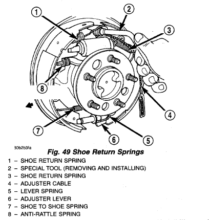
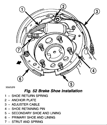
Remove shoe return springs with brake spring plier tool.
Remove adjuster cable. Slide cable eye off anchor pin. Then unhook and remove cable from adjuster lever.
Remove cable guide from secondary shoe and anchor plate from anchor pin.
Remove adjuster lever. Disengage lever from spring by sliding lever forward to clear pivot and work lever out from under spring.
Remove adjuster lever spring from pivot.
Disengage and remove shoe to shoe spring from brake shoes.
Disengage and remove adjuster screw assembly from brake shoes.
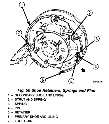
Remove brake shoe retainers, springs.
Remove secondary brake shoe from support plate.
Remove strut and spring.
Remove parking brake lever retaining clip from the secondary shoe and remove the lever.
Remove primary shoe from support plate.
Disengage parking brake lever from parking brake cable.
Remove parking brake cable guide spring.
INSTALLATION
Clean and inspect individual brake components, refer to Cleaning and Inspection found under the individual brake component.
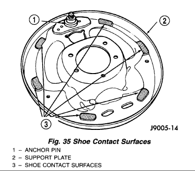
Lubricate anchor pin and brake shoe contact pads on support plate with high temperature grease or Lubriplate.
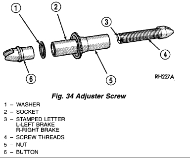
Lubricate adjuster screw socket, nut, button and screw thread surfaces with grease or Lubriplate.
Install parking brake lever to the secondary shoe and install retaining clip.
Install primary shoe on support plate. Secure shoe with new spring retainers and pin.
Install spring on parking brake strut and engage strut in primary.
Install secondary shoe on support plate. Insert strut in shoe and guide shoe onto anchor pin. Temporarily secure shoe with retaining pin.
Install anchor plate and adjuster cable eyelet on support plate anchor pin.
Install cable guide in secondary shoe and position cable in guide.
Assemble adjuster screw. Then install and adjuster screw between the brake shoes.
CAUTION: Be sure the adjuster screws are installed on the correct brake unit. The adjuster screws are marked L (left) and R (right) for identification.
Install adjuster lever and spring and connect adjuster cable to lever.
Install secondary shoe retainers and spring.
Install shoe to shoe spring to secondary shoe, then to primary shoe.
Verify adjuster operation. Pull adjuster cable upward, cable should lift lever and rotate star wheel. Be sure adjuster lever properly engages star wheel teeth.
Install the parking brake cable into guide spring and insert cable into the backing plate.
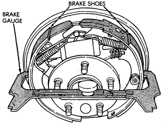
Adjust brake shoes to drum with brake gauge.
Install wheel and tire assembly.
Remove support and lower the vehicle.
THE OTHER possible size drum is a 12.8". Follow these directions if they are on your vehicle. Pictures 12 to 15 correlate with these directions.
REAR BRAKE SHOES-12 1/8 INCH
REMOVAL
Raise and support vehicle.
Remove wheel and tire assembly.
Remove clip nuts securing brake drum to wheel studs.
Remove brake drum.
Vacuum brake components to remove brake lining dust.
Unhook adjusting lever return spring from lever.
Remove lever and return spring from lever pivot pin.
Unhook adjuster lever from adjuster cable assembly.
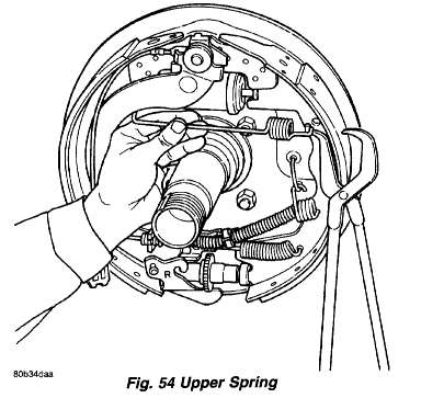
Remove shoe-to-shoe upper spring.
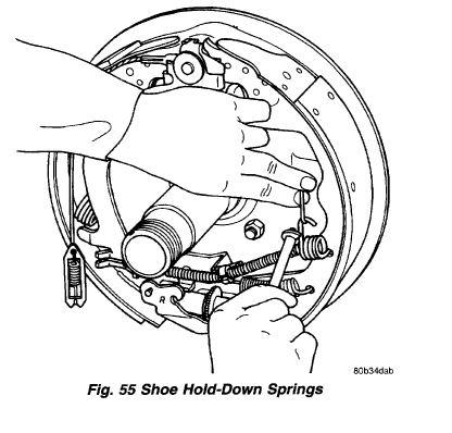
Remove shoe hold-down springs.
Disconnect parking brake cable from parking brake lever.
Remove shoe-to-shoe lower spring and adjuster assembly.
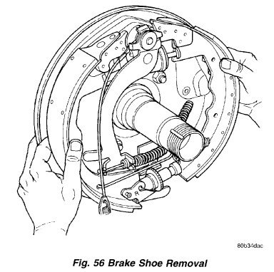
Remove brake shoes.
INSTALLATION
NOTE: Pivot screw and adjusting nut have left hand threads on left side brake and right hand threads on right side brake. Verify that adjusting nuts are installed on correct side of vehicle.
Coat contact pads on support plate with Mopar high temperature grease, multi-mileage grease, or equivalent.
Assemble adjuster, lower spring and both brake shoes. Then position the assembled components on the support plate.
NOTE: Primary shoe is installed toward the front of the vehicle and secondary toward the rear of the vehicle.
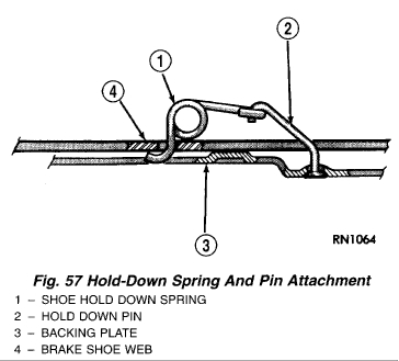
Install brake shoe hold-down springs and pins. Be sure hold-down pins are seated in support plate and springs are connected.
Insert parking brake cable through parking brake cable guide spring to parking brake lever. Be sure cable end is properly secured in lever.
Install upper spring.
Position adjuster lever return spring on pivot.
Install adjuster lever.
Attach adjuster cable to adjuster lever. Be sure cable is properly routed.
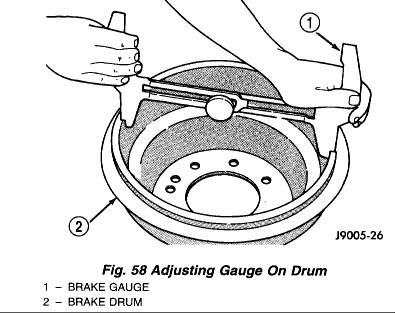
Adjust brake shoes to drum with brake gauge.
NEXT, to properly adjust the brake shoes, follow these directions. The remaining pictures are related to this procedure.
2000 Dodge or Ram Truck RAM 3500 Truck 2WD L6-5.9L DSL Turbo VIN 6
Vehicle � Brakes and Traction Control � Drum Brake System � Brake Shoe � Adjustments
ADJUSTMENTS
OVERVIEW
The rear drum brakes are equipped with a self-adjusting mechanism. Under normal circumstances, the only time adjustment is required is when the shoes are replaced, removed for access to other parts, or when one or both drums are replaced.
Adjustment can be made with a standard brake gauge or with adjusting tool. Adjustment is performed with the complete brake assembly installed on the backing plate.
ADJUSTMENT WITH BRAKE GAUGE
Be sure parking brakes are fully released.
Raise rear of vehicle and remove wheels and brake drums.
Verify that left and right automatic adjuster levers and cables are properly connected.
Insert brake gauge in drum. Expand gauge until gauge inner legs contact drum braking surface. Then lock gauge in position.
Adjusting Brake Shoes With Gauge
Reverse gauge and install it on brake shoes. Position gauge legs at shoe centers as shown. If gauge does not fit (too loose/too tight), adjust shoes.
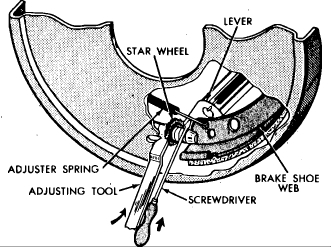
Pull shoe adjuster lever away from adjuster screw star wheel.
Turn adjuster screw star wheel (by hand) to expand or retract brake shoes. Continue adjustment until gauge outside legs are light drag-fit on shoes.
Install brake drums and wheels and lower vehicle.
Drive vehicle and make one forward stop followed by one reverse stop. Repeat procedure 8-10 times to operate automatic adjusters and equalize adjustment.
NOTE: Bring vehicle to complete standstill at each stop. Incomplete, rolling stops will not activate automatic adjusters.
ADJUSTMENT WITH ADJUSTING TOOL
Be sure parking brake lever is fully released.
Raise vehicle so rear wheels can be rotated freely.
Remove plug from each access hole in brake support plates.
Loosen parking brake cable adjustment nut until there is slack in front cable.
Fig. 6 Release type brake adjuster
Insert adjusting tool through support plate access hole and engage tool in teeth of adjusting screw star wheel.
Rotate adjuster screw star wheel (move tool handle upward) until slight drag can be felt when wheel is rotated.
Push and hold adjuster lever away from star wheel with thin screwdriver.
Back off adjuster screw star wheel until brake drag is eliminated.
Repeat adjustment at opposite wheel. Be sure adjustment is equal at both wheels.
Install support plate access hole plugs.
Adjust parking brake cable and lower vehicle.
Drive vehicle and make one forward stop followed by one reverse stop. Repeat procedure 8-10 times to operate automatic adjusters and equalize adjustment.
NOTE: Bring vehicle to complete standstill at each stop. Incomplete, rolling stops will not activate automatic adjusters.
Let me know if this helps or if you have questions. Also, you listed the engine as a 5.8 which does not exist. I based everything on the 5.9L Cummins.
Take care,
Joe
Images (Click to make bigger)
Wednesday, March 31st, 2021 AT 10:28 AM