Primary to ignition coils and MAF sensor wiring diagram

Tiny
MONCHO6685
  • MEMBER
  • 2001 HYUNDAI SANTA FE
  • 2.4L
  • 4 CYL
  • 2WD
  • AUTOMATIC
  • 138,949 MILES
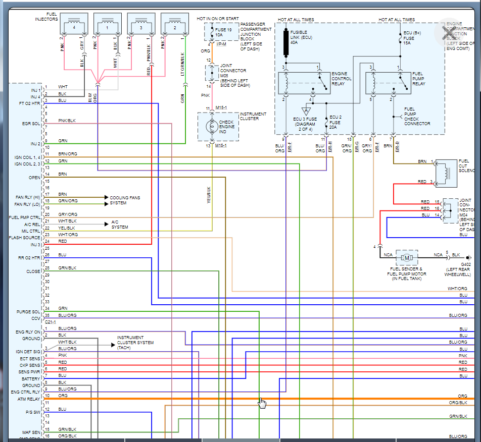
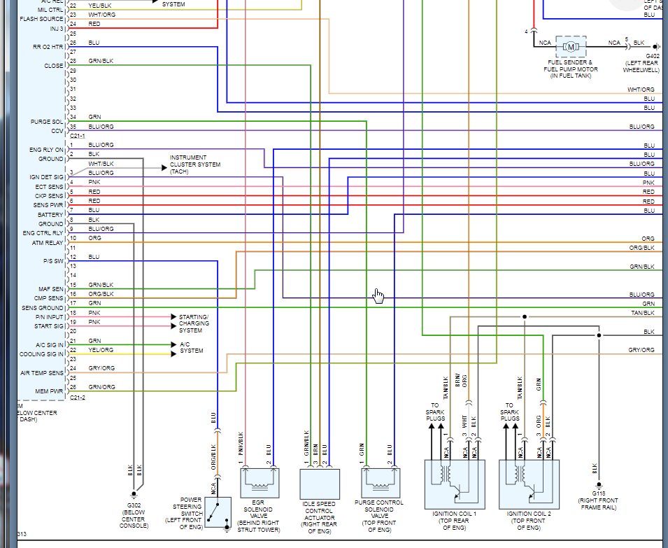
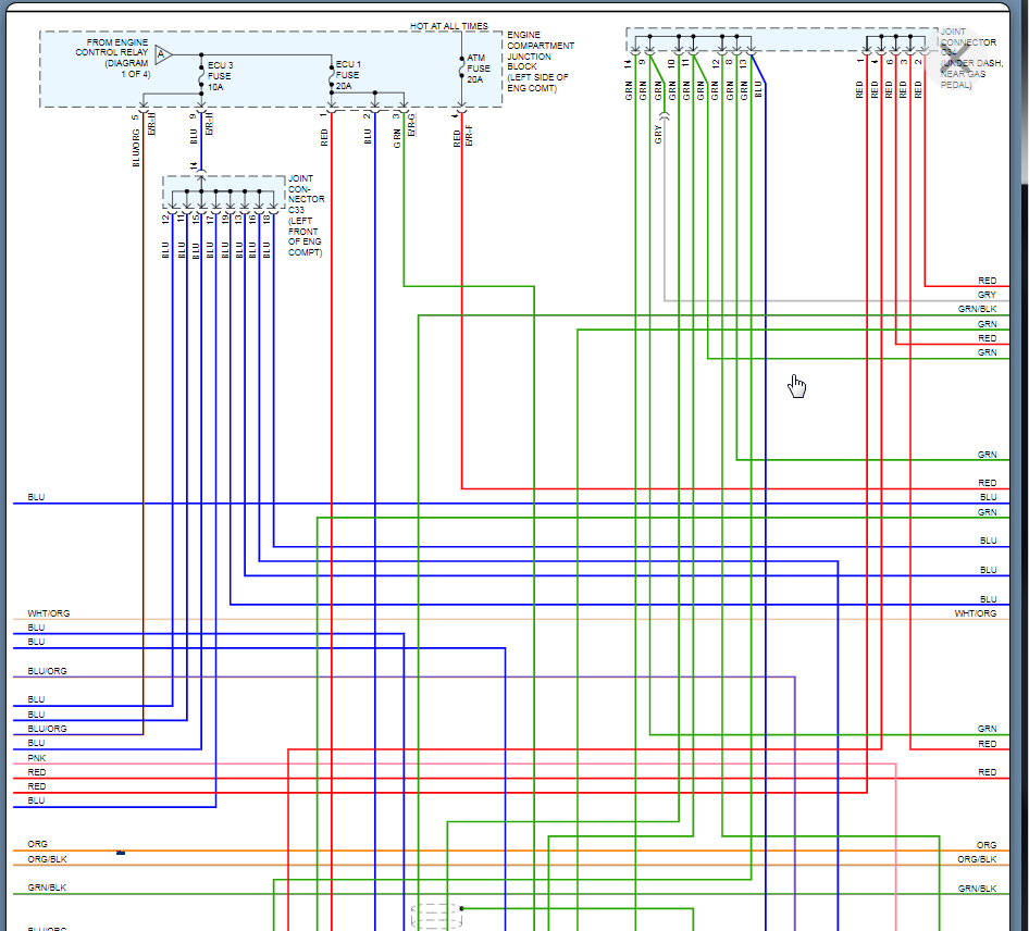
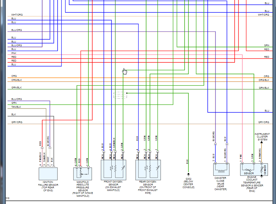
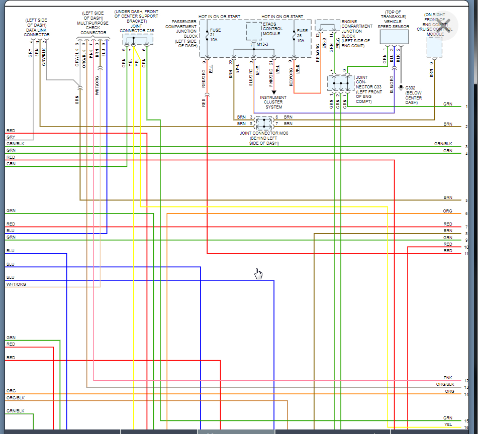
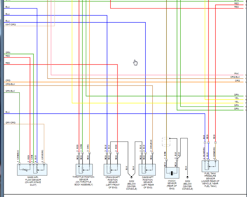
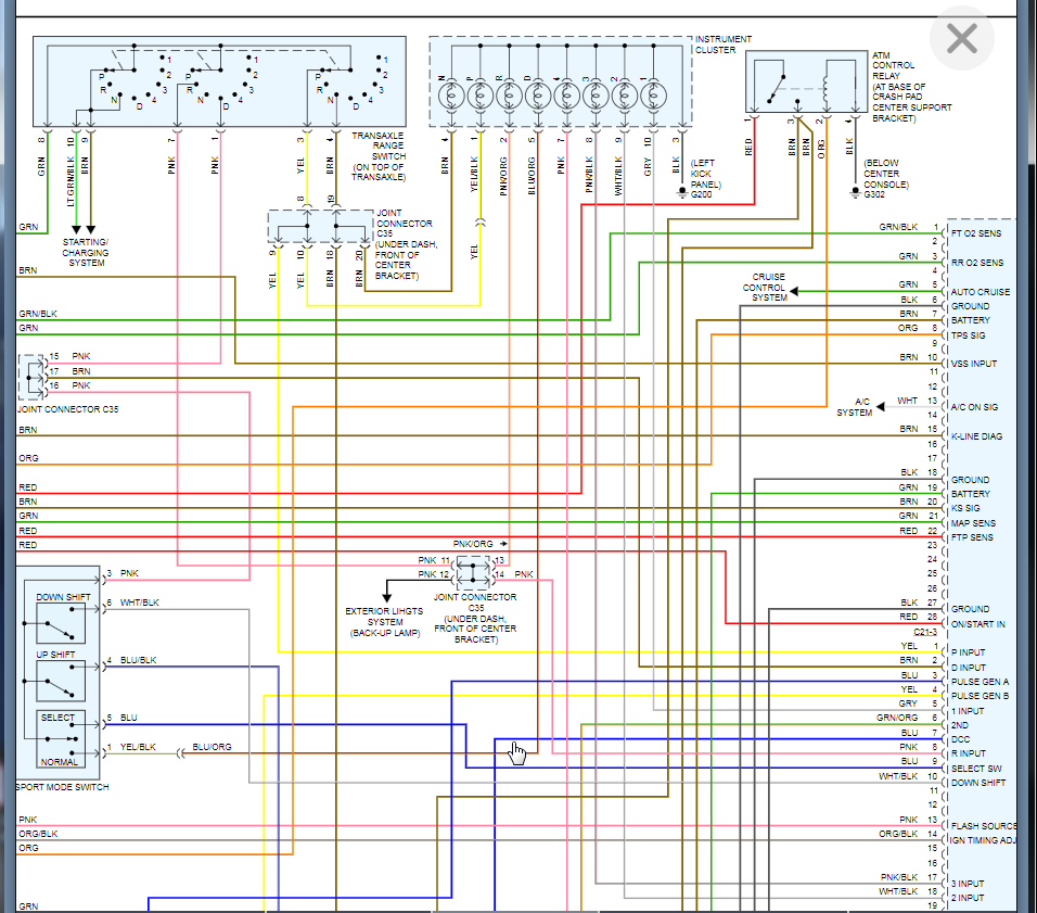
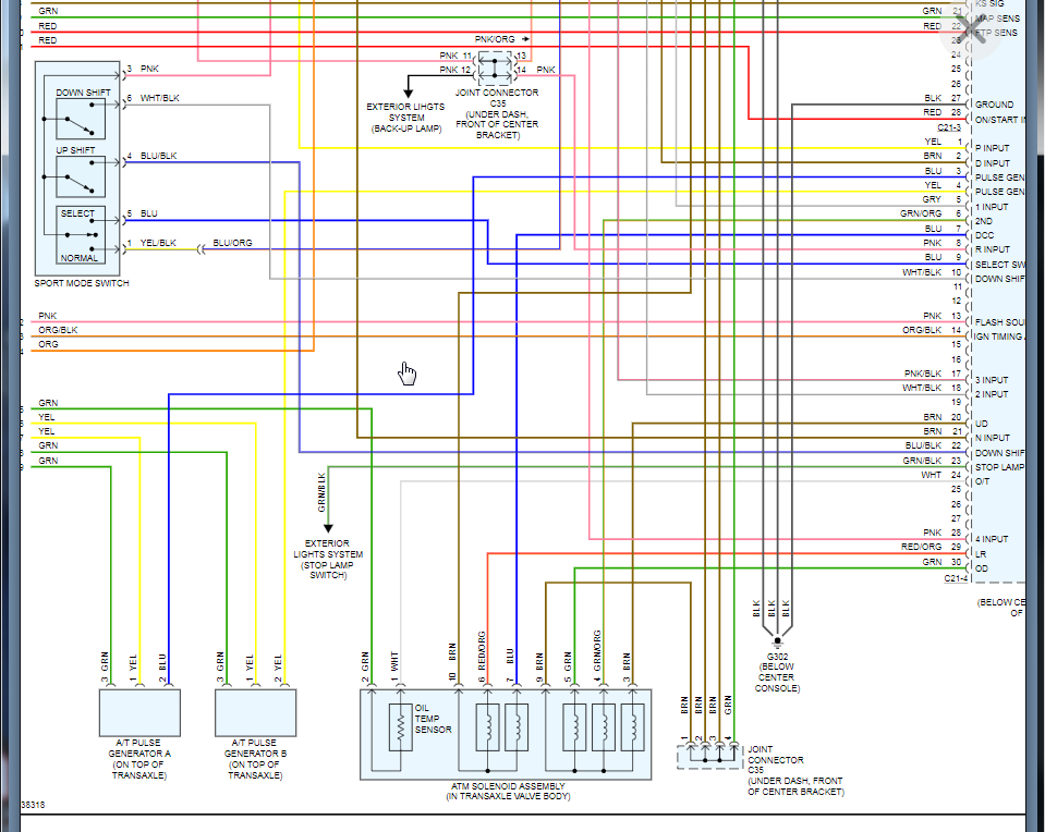
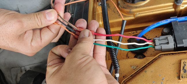
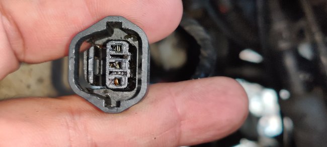
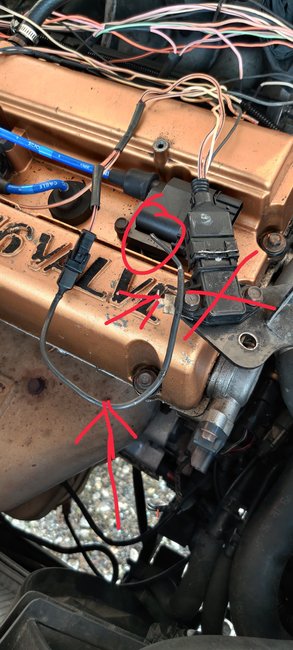
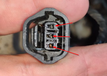
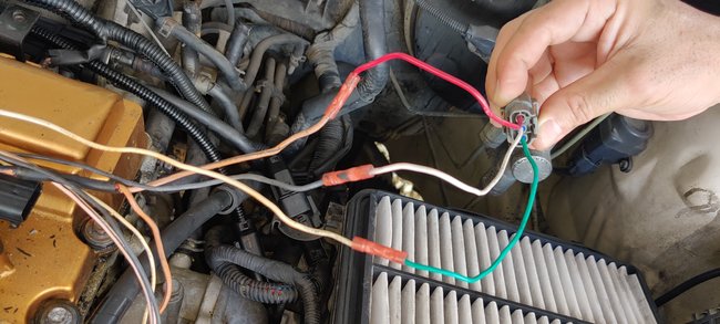
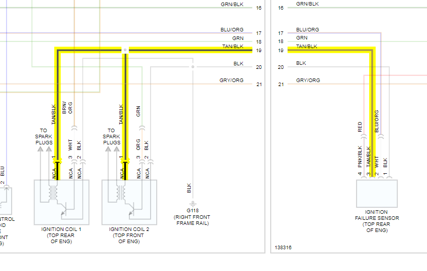
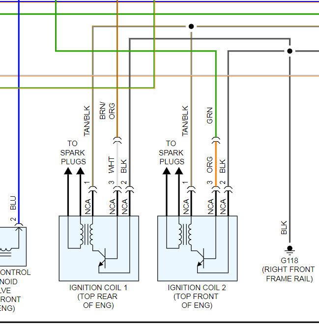
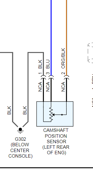
Hello. My friend bring me his vehicle because it has a check engine light on. One code for the IAT sensor and I found something more. Someone change the plugs of the ignition coils but they use a butt connectors to make the connections. I want to know if the wires are correctly connect with the diagram and change the butt connectors with welding. I need the MAF sensor wiring diagram to test it and see if there's a problem on the connector, the wires or the ECM, PCM, ECU.
I appreciate your help.
Thanks,
Juan Marin
Friday, September 18th, 2020 AT 11:21 AM

10 Replies

Tiny
KASEKENNY
  • MECHANIC
  • 18,907 POSTS
I included the complete PCM wiring diagram so it includes everything you will need. However, can you get some pictures of what you are talking with the butt connectors? I assume you are talking about someone just make a wiring repair and used these. If so, you can just cut them out and solder the wires back together then shrink wrap them so they are done the proper way.

Do you have any issues with the coils or are you just doing as a precaution?

FYI - The wiring diagrams are split in half so there is overlap but there are 8 pages. 2 pages per actual wiring diagram. So that means there are 4 pages in the manual but if I took screen shots of them as full pages, it would be pretty small and you would not be able to see it.
Was this
answer
helpful?
Yes
No
+1
Friday, April 16th, 2021 AT 2:17 PM
Tiny
MONCHO6685
  • MEMBER
  • 118 POSTS
That's exactly what I want to know if the butt connectors are creating the little problem on idle (like a little misfire) and check with the diagram if they are properly connected. I have a second problem with the IAT code and I want to check the plugs, wires, because the owner told me is a new MAF sensor.
I'll send you photos tomorrow.
Thanks,
Juan Marin
Was this
answer
helpful?
Yes
No
Friday, April 16th, 2021 AT 2:17 PM
Tiny
KASEKENNY
  • MECHANIC
  • 18,907 POSTS
Sounds good. Butt connectors could cause high resistance or even open circuits so if it were me, I would just remove them even if they are not causing the issue.

Pictures will help and what was the code for the IAT that you have?
Was this
answer
helpful?
Yes
No
Friday, April 16th, 2021 AT 2:17 PM
Tiny
MONCHO6685
  • MEMBER
  • 118 POSTS
That's what I think about the butt connectors.
I send you some photos of what I found in this vehicle.
The dtc code for the IAT is p0113.
Circuit high input. I need to check the entire harness to eliminate some faulty shorted cable etc.
But I send you a picture that I want to know if I miss something. The photo have the ignition misfire sensor, but I ask you? You saw a circle for the sensor, a big arrow showing the wire, a little arrow showing where the missing part or cut goes, but I didn't found that part on the wiring diagram, tan black wire that goes from the ims to the coils, I miss something on the wire diagram?
I have a lot to repair.
See the photos and let me know what you think.
Att. Juan Marin
Was this
answer
helpful?
Yes
No
Friday, April 16th, 2021 AT 2:17 PM
Tiny
KASEKENNY
  • MECHANIC
  • 18,907 POSTS
Oh man. This does not look good. Thanks for the pictures. However, each one that you took has to be repaired including the connector end as the terminals look crushed.

As for the misfire sensor, I assume you mean the knock sensor? However, that does not look like the knock sensor. I attached the location view of it. It does appear to be pulled out of that connector but it is odd that you don't have a code for it.

However, that IAT code, I am sure is a wiring issue based on these photos. So you can just test for a short to power, ground, and open from the sensor to PCM. That will tell you if is a wiring issue.
Was this
answer
helpful?
Yes
No
+1
Friday, April 16th, 2021 AT 2:17 PM
Tiny
MONCHO6685
  • MEMBER
  • 118 POSTS
Hello Kasekenny1, I got a lot of solder to do. I need, if you can send me the position of the wires on the plugs (cam sensor and ignition coils) to be sure they're on the right position.
About the ignition misfire sensor I sent you a photo. What I need to know if I miss something on the wiring diagram about a wire that came from the sensor (tan/black wire) as you see on the photo (the x is the ignition misfire or failure sensor) the tan/black wire that came from the sensor split in two, one goes to the ignition coils and the other part of the wire with the connector goes from tan/black to a single black wire that someone cut. That's the part the I want to be sure.
Thanks for your help,
Att. Juan
Was this
answer
helpful?
Yes
No
Friday, April 16th, 2021 AT 2:17 PM
Tiny
KASEKENNY
  • MECHANIC
  • 18,907 POSTS
Okay. Then tan/black wire goes from the failure sensor to both coils. I attached the highlighted wiring diagram below. Then the second diagram is a close up of the coils. Lastly is a close up of the cam sensor.

Let me know if I missed something but I think that will get you what you need.
Was this
answer
helpful?
Yes
No
+1
Friday, April 16th, 2021 AT 2:17 PM
Tiny
MONCHO6685
  • MEMBER
  • 118 POSTS
Hello kasekenny1. I send you this photos to show you the wire harness the vehicle listed above has and to show you the missing part that I told you before the one that someone cut it. The redx is the ignition misfire sensor and the red circle is part that was cut it.
I send you too a short video of the speedometer. I want to know why it moves like that?
I want to verify if that's the correct wire harness for that model of the vehicle and for the year. 2001 Santa Fe LX, a/t, 2.4l.
Thanks,
Juan Marin
Was this
answer
helpful?
Yes
No
Friday, April 16th, 2021 AT 2:17 PM
Tiny
MONCHO6685
  • MEMBER
  • 118 POSTS
Hello KASEKENNY1. I send you this photos to show you the wire harness the vehicle listed above has and to show you the missing part that I told you before, the one that someone cut it. The redx is the ignition misfire sensor and the red circle is part that was cut it.
I send you too a short video of the speedometer. I want to know why it moves like that during the scan process.
I want to verify if that's the correct wire harness for that vehicle model and for the year. 2001 Santa Fe LX, a/t, 2.4l.
Thanks,
Juan Marin
Was this
answer
helpful?
Yes
No
Friday, April 16th, 2021 AT 2:17 PM
Tiny
KASEKENNY
  • MECHANIC
  • 18,907 POSTS
Yes. The speedometer should do that during the scan process. It is a self check where it checks the operation of it.

As for the harness, I am not sure but when I run the part number, I come back with a 2000-2006 Santa Fe but it doesn't give me an engine. So that normally means it fits either engine which would make sense because there is not much different between the 2.4 and 2.7L engines.
Was this
answer
helpful?
Yes
No
+1
Friday, April 16th, 2021 AT 2:17 PM

Please login or register to post a reply.

Sponsored links