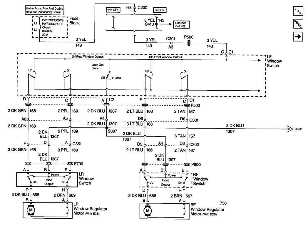
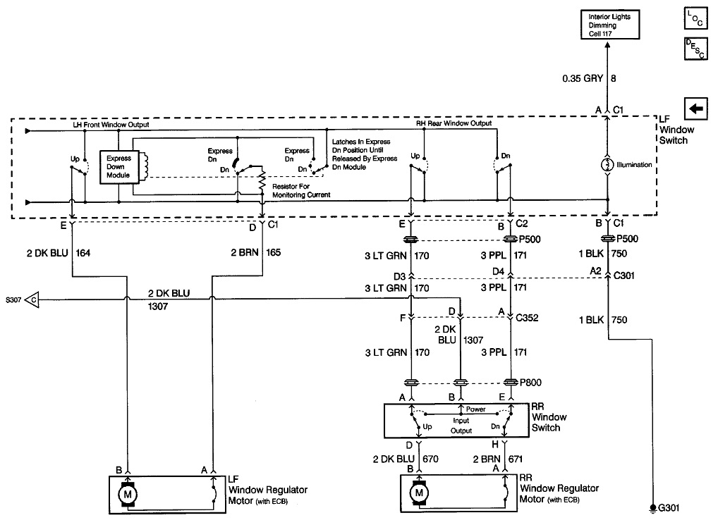
Here's what I put together last night. Every two diagrams go together as the left and right halves.
In those first two diagrams, every window switch is released. As such, they are all connected to ground. If you go to any window motor and unplug any one of its wires, both of them must read continuity to ground. The reason for unplugging one of them is both will read okay if just one is okay because one with a break in it will read through the motor, then to ground through the good wire. Both wires have to be good for the motor to run either way.
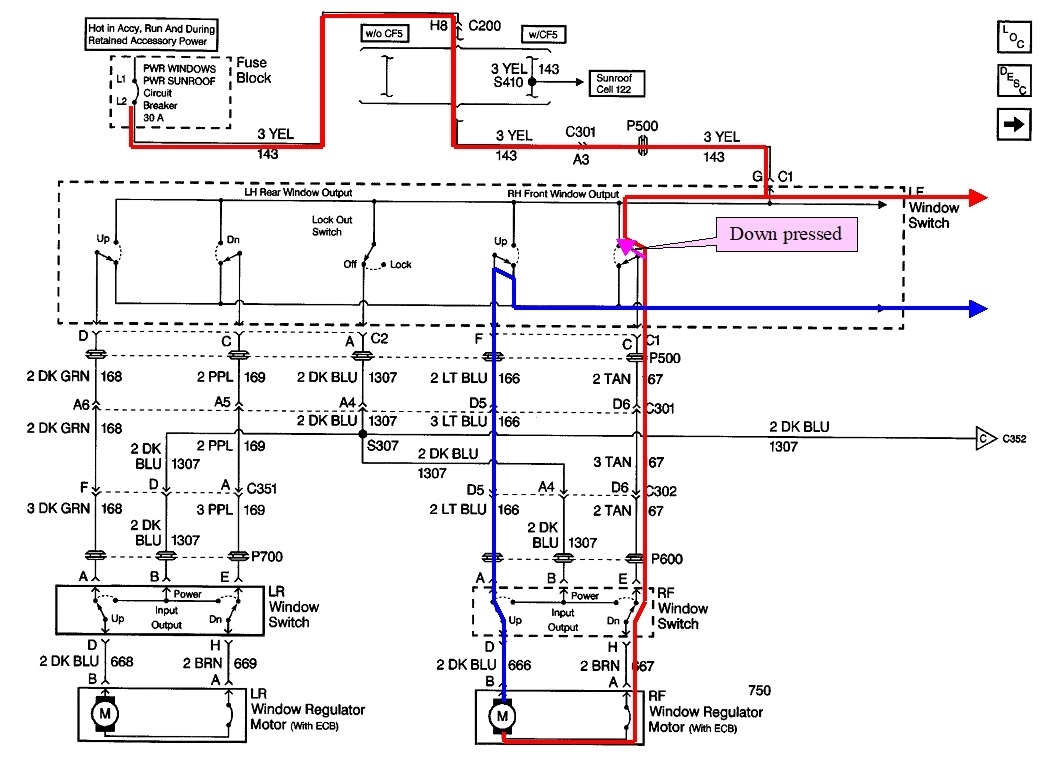
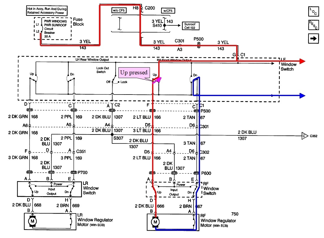
The third and fourth are the same diagrams, but I highlighted the current path for the right front window. The red circuit is the 12-volt supply from the circuit breaker. Current flows through the door hinges, then shows up at the driver's switch on the yellow wire.
I gotta stop here and point out all of the voltage readings are only valid when everything is plugged in. That especially applies to this type of circuit. A common source of trouble is a wire that has frayed between the door hinges. If the switch is unplugged, all it takes for a voltmeter to falsely "see" 12 volts is for one tiny strand of that wire to still be intact, but there's no way enough current can get through to run the window motor. When everything is plugged in and you try to run the motor with that one strand, most of the 12 volts will be "dropped" across that break, leaving just a fraction of a volt to be measured at the switch or motor.
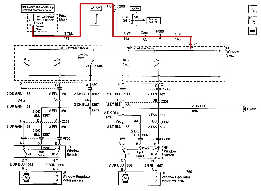
In this diagram, the "Down" switch is pressed. Current flows through it, then back through the driver's door hinges, over to the right side, through those hinges, then to the right front passenger's switch. The "Down" half of the passenger's switch is released, so current continues through that part, and finally, to the motor. You should measure the full 12 volts on that brown wire.
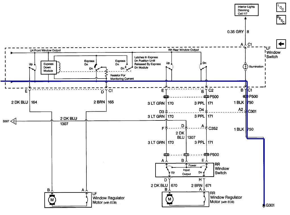
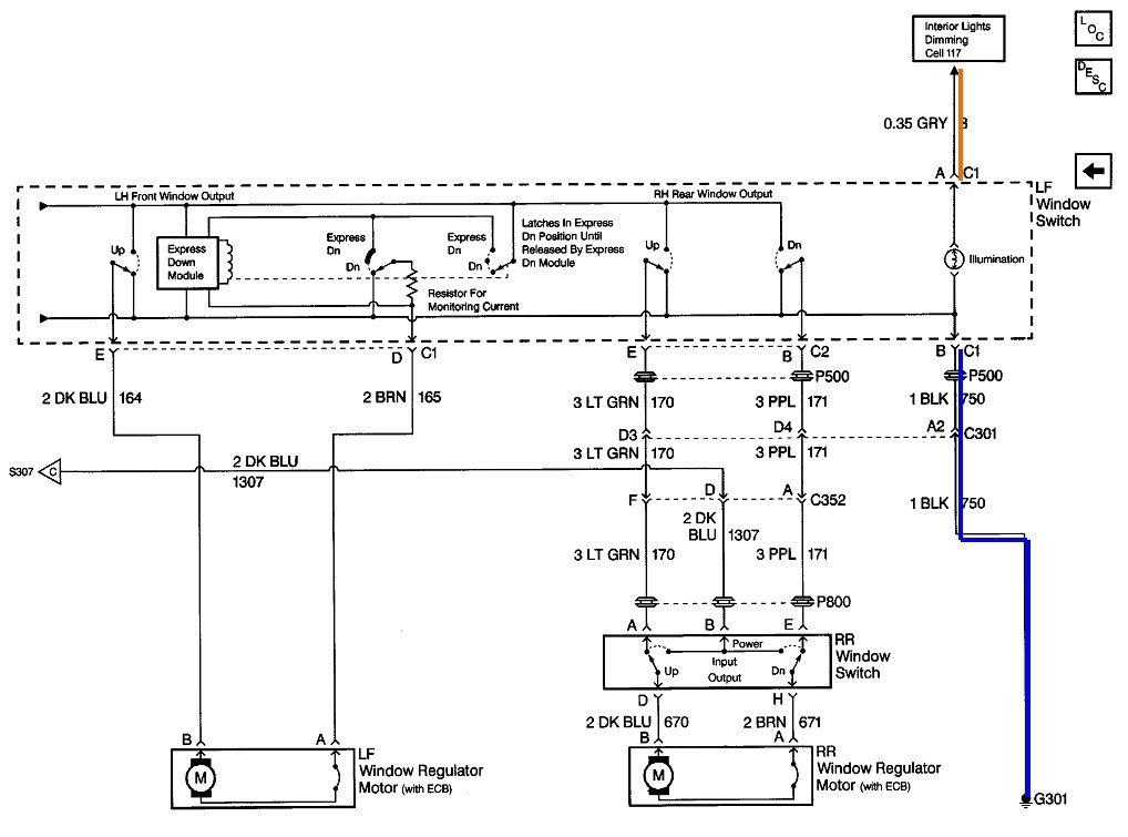
All of the 12 volts is used up, or "dropped" across the motor. There will be 0 volts everywhere after the motor. Current continues through the motor, through the dark blue wire, up through the released "Up" part of the passenger's switch, through the door hinges on both sides, then back to the driver's switch on the light blue wire. In that switch, current continues through the released "Up" part of it, then onto the ground circuit. Current flow continues over to the fourth diagram, then out the ground terminal, "B" in connector "C1". From there it goes through the door hinges for the last time, then to ground on the body. That black ground wire is bolted on at ground location, "G301". From there current flows back to the battery's negative post.
The point of this sad story is when a switch is pressed, you should find 12 volts at every point on the red highlighted circuit, and 0 volts everywhere on the blue circuit.
If you aren't clear on this already, every window switch has two totally separate switches in it. Only one or the other changes position depending on which way the knob is pushed. When released, each one connects one of the motor's wires to ground. When the knob is pressed, one of those switches stays grounded, and the other one switches from ground to the 12-volt supply. That applies the 12 volts to one motor terminal.
When the knob is pressed the other way, the other switch is moved from being connected to ground to being connected to the 12-volt supply. The first switch stays connected to ground. Now the 12 volts and the ground are reversed, so the motor runs the other way.
In the fifth and sixth diagrams, the right front window switch in the driver's switch assembly is pressed, "Up". Current flow is shown again with the red and blue highlighted circuits. The "Down" switch is released so it's tied to ground. The "Up" switch puts 12 volts on the motor's top terminal where ground used to be. The polarity is reversed from before, so now the window goes up.
Couple notes of value. First, as you can see, the red and blue circuits are the same on the driver's switch part of both diagrams. It's only after that switch that the polarity changes. Of more importance, every switch is a single pole, double throw, (SPDT) switch. In the pressed position, one pair of contacts are in use. In the released position, a different pair of contacts are in use. When activated, one switch moves from ground to 12 volts, then current flows through that one, ... And the other three released switches. All four switches have to work for current to flow through the motor.
To say that a different way, a dead passenger window can be caused by a defective passenger switch or a defective driver's switch. A break anywhere in the red or blue circuits will also cause the motor to be dead.
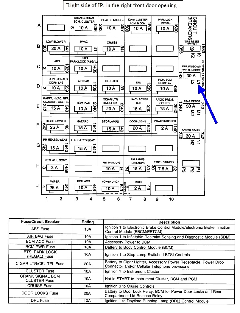
Now to narrow this down based on your observations, we can't assume 12 volts is getting to the driver's switch based on its light. That comes in on a different wire, (orange highlight, top right of the eighth diagram), from the dash light circuit, (gray wire). We need to have 12 volts on the yellow wire. If that is missing, a broken wire between the hinges is the best suspect. That can cause this two ways. The first is a simple break. The windows could work intermittently, especially when opening and closing the door which moves the wires around.
The other possibility is the yellow 12-volt wire and any of the other wires are broken and they're touching. That can put a dead short on the yellow wire and trip the circuit breaker. Being for a safety system, that's an auto-resetting thermal circuit breaker. You can often get a clue by feeling it. If the short is on a wire that only gets 12 volts on it when a switch is pressed, the circuit breaker will be cold. If the 12-volt feed wire is shorted, the circuit breaker will be hot. It will trip, reset as it cools down, then trip again repeatedly. The idea behind this type of fuse device is a momentary short could occur in a crash. A blown fuse is permanent. A thermal circuit breaker will reset and may work long enough to get a window down. Thermal circuit breakers are used quite often in wiper circuits for the same reason.
The last place to look is the ground circuit, (black wire). This is also in use for the illumination light in the driver's switch so we know at least one or two strands of that wire have to be okay. If that is the case, trying to run a window turns on the much higher current flow through the motor. It won't be able to get through the partially-broken ground wire. Instead, most or all of that 12 volts will be dropped across the break instead of across the motor. Any voltage on that black wire reduces the voltage across the light bulb, so the bulb dims or goes out.
Images (Click to make bigger)
Saturday, April 8th, 2023 AT 1:13 PM