In your original post, you said, " the positive wire was okay, but the negative wire is null". What does, "null" mean? Do you have continuity or an open circuit?
Be aware continuity tests in high-current circuits like this are not the best test. All you need is one tiny strand of wire remaining intact to get a good reading, but you'll never get enough current through there to run a window motor. Voltage tests are far more accurate. You already found the 12-volt supply is okay. From there, when you press a switch, current flows from that 12-volt supply, through the one activated switch of the four in that switch assembly, to the motor, through it, back to the switch assembly and through a different, released set of switch contacts. By this time, once you passed through the motor, you are supposed to see 0 volts while still pressing the switch. You'll find some voltage, usually the full 12 volts, if the ground wire is broken, or if that second set of switch contacts is burned.
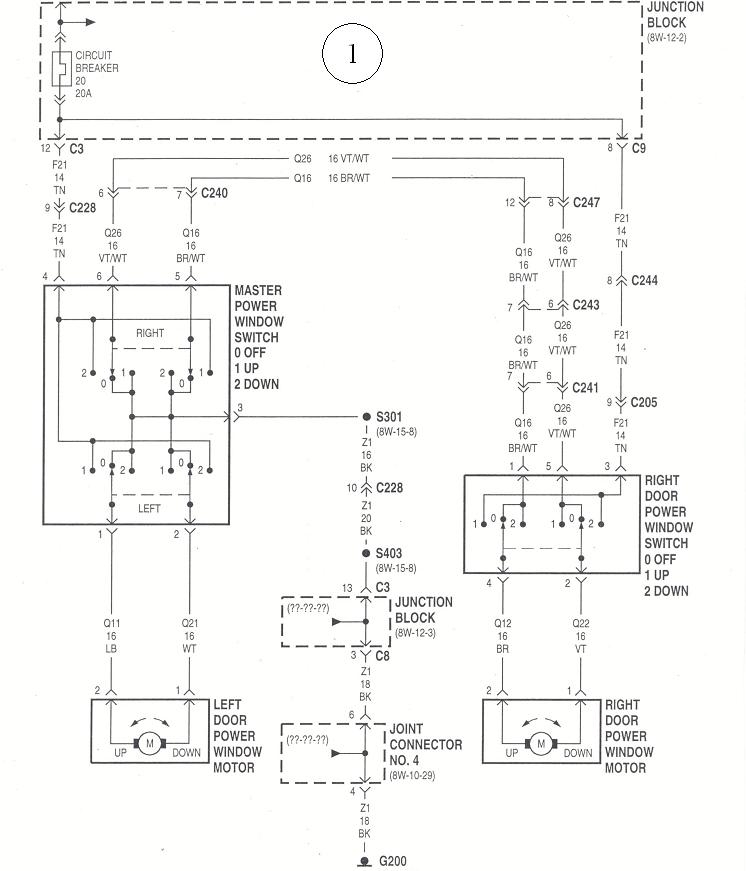
See if this is of any help. These are diagrams I prepared previously using the circuit for a 1997 Dodge Dakota truck. While it looks a little intimidating at first, it is very representative of what is used by most other manufacturers. This is for the passenger's window, so there's both switch assemblies on both front doors involved. Since all of your windows are dead, concentrate on just the less-complicated driver's window. When you solve that, the rest will work too.
Here goes:
Chrysler's instructors are given vehicles to use in their classes, then after they've been poked and prodded for a couple of months, they don't want to release them to the public. Their solution is to donate them to technical college Automotive programs. We received a '97 Dakota that I used for electrical training for many years. The diagram works well for explaining power windows because there's just two front windows to worry about. When you have four windows, the two rear circuits are the same as the right circuit in this diagram. The wiring diagram for your van is almost the same as this one, except, of course, the wire colors will be different. Also, if your van has a lock-out switch on the driver's switch assembly so kids can't play with their windows, that would be in the top-most wire right under the circuit breaker. Diagram 1 shows the entire system.
There's a number of shortcuts and multiple ways to diagnose a power window problem, but they won't make sense until the circuit is understood. This diagram shows the operation of a passenger window with a passenger switch and another one on the driver's door for that window. The driver's window circuit is less complicated.
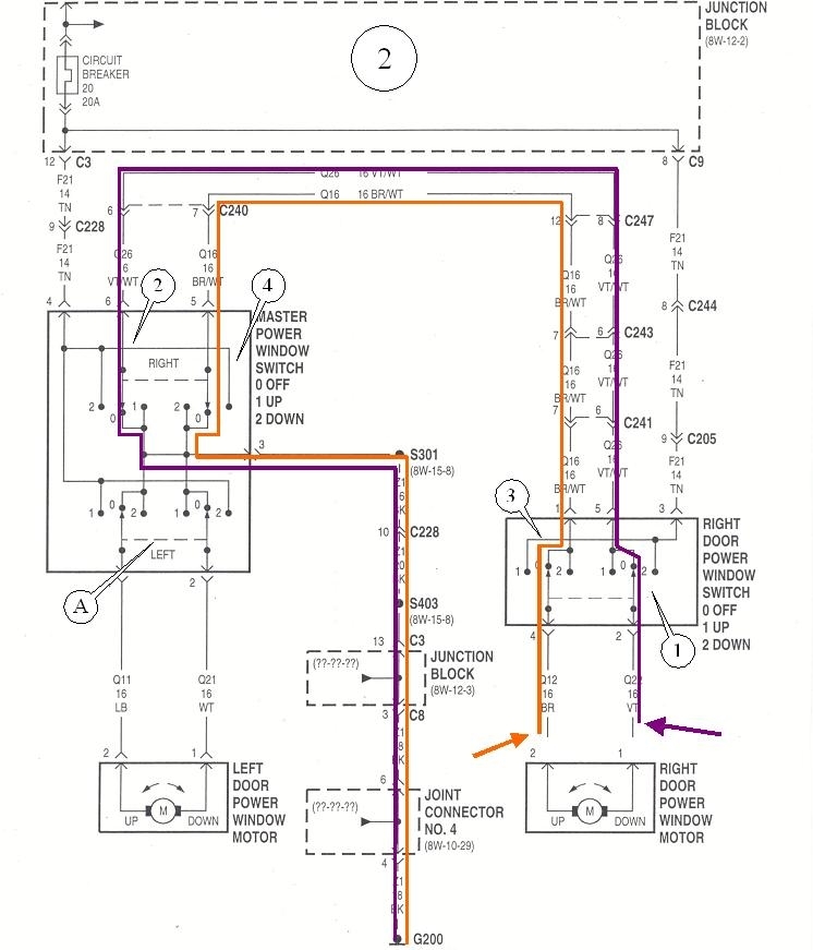
First of all, every switch actually has two double-throw switches inside it, and all current for a passenger window always goes through all four switches, regardless of which way the motor is running or which switch is activated. Second, when you press a switch, one of its two internal switches remains released and the other one switches. Third, when the switches are released, they are completing the ground circuit for the motor. That provides a useful test if you already have the door panel off. Continuity can be measured to test the wiring and switches, but to be accurate, the motor must be unplugged, as shown in diagram 2, otherwise an open circuit will appear to be okay by reading through the motor.
To do these tests, ground one probe of the ohm meter to a paint-free point on the body, and touch the other probe to one terminal in the plug you removed from the motor. Ideally you'd find 0 ohms, but in the real world, expect to find a very low resistance, in the order of two to five ohms. If that test is okay, move the probe to the other wire in the motor's connector. This one should also have very low resistance. I apologize if this is overly-basic. I'm typing this the way I described it in the classroom to people who just learned basic electrical theory a few weeks earlier. The probe will be at the purple arrow, then at the orange arrow, in diagram 2.
In the second diagram, the purple outline shows the first circuit being tested. Start at the purple arrow, then follow that wire up through switch # 1, which is released, through the passenger door hinges, over to the driver's side and through the driver's door hinges, through switch # 2 which is also released, then out to ground. That ground wire also goes through the driver's door hinges, then it's bolted to the body.
The second circuit, outlined in orange, is identical and also has two released switches in its circuit. The exciting point of interest is you can test the wiring and switches on any car or truck this way without having to know wire colors. It's when a circuit has a break that we have to look further, but we still don't have to be concerned with wire colors. The two most common failures are broken or frayed wires between the door hinges, and a burned or pitted switch contact. If you have a replacement switch on hand, pop it in as a quick test by substitution. Inspecting wires between the hinges can take a little time to wrestle the rubber boot out of the way.
Part 2
The dashed line, (item "A" in the second diagram, indicates both switches move together. That doesn't actually happen, but it's the only way the circuit can be drawn to make sense. If you look at the two lower switches for the driver's window that "A" is pointing to, it is shown as released. If you press "down", both switches move to the right, shown as position "2". On the left switch, position "0" and position "2" are tied together, so nothing has changed there. The right switch moves at the same time, but in this one, it breaks the contact to the ground terminal and makes a connection to the 12 volt terminal. That applies 12 volts to one motor terminal while the other motor terminal remains grounded. The motor runs one way. By pressing that switch to the "Up" position, 12 volts would be applied to the other motor terminal, and with the polarity reversed, it runs the other way.
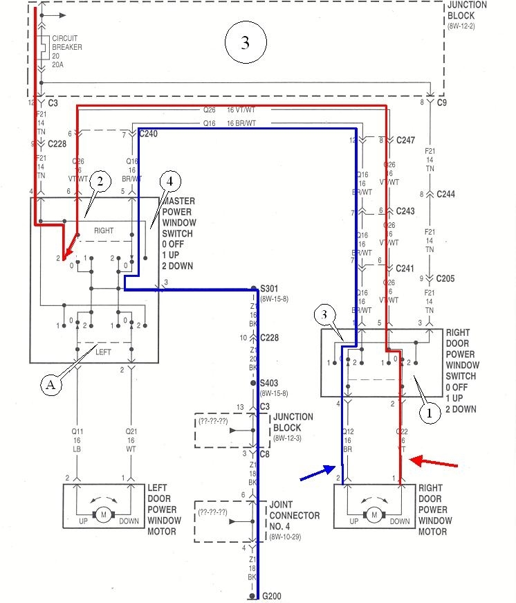
The third diagram shows the driver's switch for the passenger window pressed "down". Switch # 2 is moved away from its ground contact and is connected to its 12 volt contact. Follow the red circuit and see that it goes through the released switch # 1 in the passenger's switch, then to the motor. The motor's ground circuit is the same as before. Current goes through switch # 3 in the passenger's switch, and switch # 4 in the driver's switch, both of which are still released. The point of this great and wondrous story is current has to flow through four sets of switch contacts for the motor to run. A burned contact on any one of them will stop the motor from running. If either switch # 1 or 3 in the passenger switch has a burned contact, that window won't run either way from the driver's switch.
If the driver's switch is moved the other way, from position 0 to position 1, the left side, (red circuit), will remain grounded and the right side, (blue circuit), will get the 12 volts applied to it, so the motor will run the other way. The same thing happens at the passenger's switch assembly. Moving the switch one way breaks the ground for one of the motor's wires and applies 12 volts to it, and the motor runs one way. Moving the switch the other way applies 12 volts to the other wire, and the motor runs the other way. Wire F21, 14 gauge, tan is where the 12 volts comes from for when the passenger's switch is used. Notice there is no wire going to ground in that area. Grounding for the motor always goes back through the driver's switch's assembly, then to ground. Also note that only one of those two circuits, the purple one or the orange one provide the ground at a time, depending on which way the passenger's switch is activated. The two switches inside the driver's switch assembly are both released, but each one is still using a pair of contacts that can become burned or pitted. If, for example, switch # 4 has a burned contact in position "0" where it's released, there will be an open circuit in the blue circuit, so there will be no ground for the motor when switch # 1 is activated. The passenger's window will not go down when the passenger's switch is pressed, but the problem is caused by the driver's switch assembly. This is why you don't know which switch is defective, regardless of which window works or is dead one way or both ways. It can always be either switch.
If that magnificent story makes sense, I can complicate it even more. When you get to any system with a feature that makes the window operate without you having to push and / or hold the switch, there will be relays involved, and some type of additional circuitry to run them. A relay will take the place of each internal switch, #s 1 - 4, and the circuitry will turn the relay on and keep it on long enough for the window to get to where it's going. The two common examples of this include the "auto-down" feature that runs the window all the way down when you only tap the switch momentarily. I guess the engineers didn't have enough confidence in our ability to hold a switch for all of three or four seconds, but I have to admit, it can be nice to have. The other application is for a power window that must roll down an inch before opening and closing the door, so the glass clears a convertible top. There's no one inside the car to push the switch when you're getting in, so computer circuitry is needed to run the relays to do that function.
While the relays do add complexity to the circuit, treat the relays' contacts the same way as you treat regular switch contacts when it comes to testing the circuit. GM often uses power window switches that have two relays inside the assembly. There are some cars that have a relay module in the dash. Those relays do the same switching that the door switches used to do, and the door switches are of a simpler design and they just turn the relays on and off. I'm not familiar enough with those systems to talk intelligently about them.
Images (Click to enlarge)
Nov 9, 2019 at 5:46 PM