The procedure below with some pictures.
Roy
Removal
1. If installing a new steering gear, connect the scan tool and upload the module configuration information from the PSCM (Power Steering Control Module).
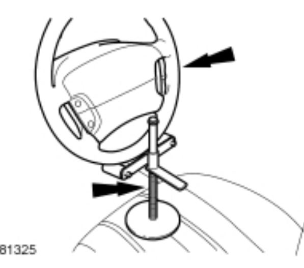
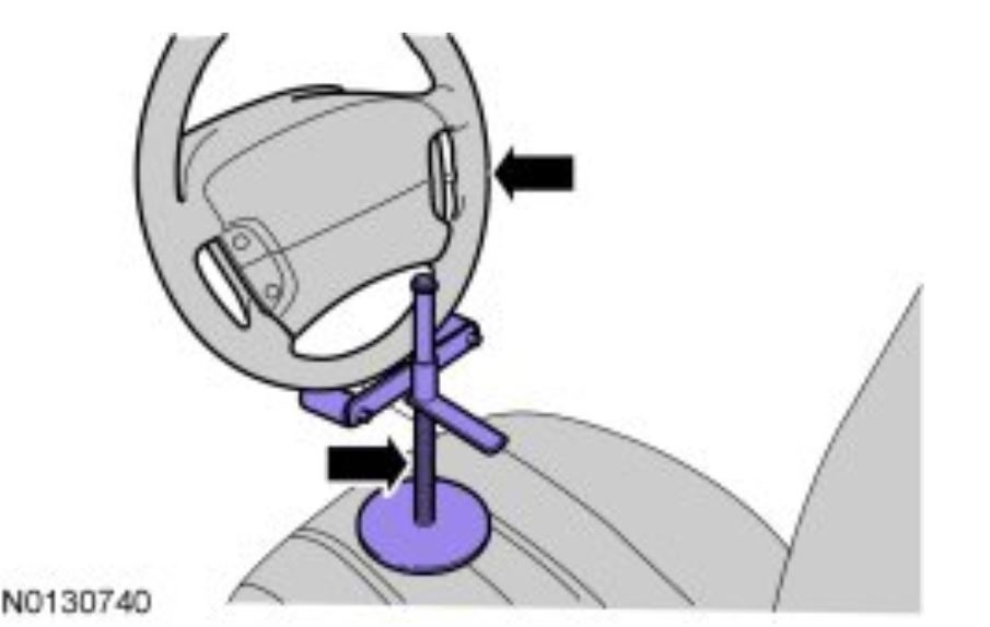
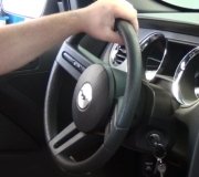
2. Using a suitable holding device, hold the steering wheel in the straight-ahead position.
ImageOpen In New TabZoom/Print
3. Remove the front wheels and tires. REFER to Section 204-04A, Wheel and Tire See: Wheels and Tires > Removal and Replacement > Wheel and Tire.
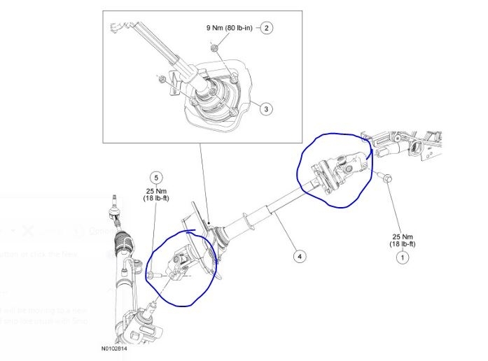
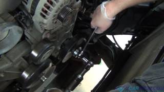
4. Remove and discard the steering column shaft-to-steering gear bolt and disconnect the steering column shaft from the steering gear.
5. Remove and discard the 2 stabilizer bar link upper nuts.
6. Remove the 2 outer tie-rod end nuts and separate the tie-rod ends from the wheel knuckle.
7. Remove the 4 retainers and the underbody shield.
8. If equipped with a 3.5L engine, remove the exhaust Y-pipe. REFER to Section 309-00, Exhaust Y-Pipe See: Exhaust Pipe > Removal and Replacement > Exhaust Y-Pipe.
9. Remove the roll restrictor-to-subframe bolt.
10. Remove the flap heat shield bolt and position the flap heat shield to access the EPAS (Electronic Power Assist Steering) electrical connectors.
11. Remove the wiring harness-to-steering gear bolt.
12. Disconnect the 2 EPAS (Electronic Power Assist Steering) electrical connectors and detach the 2 wiring pin-type retainers from the steering gear.
13. Remove the 2 RH inner fender shield-to-subframe pin-type retainers.
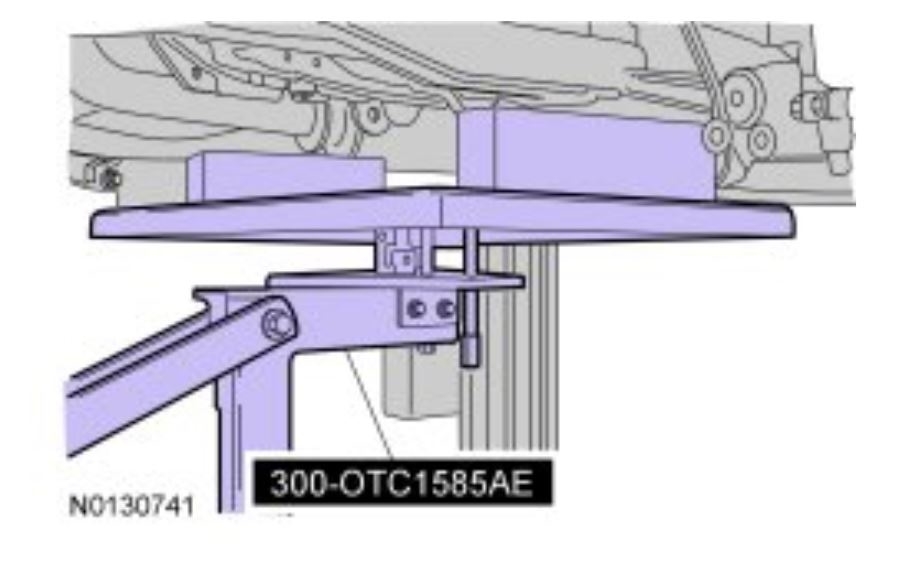
14. Position 300-OTC1585AE under the subframe.
ImageOpen In New TabZoom/Print
15. Remove the 2 subframe rearward bolts, the 4 support bracket bolts and the 2 subframe support brackets.
16. Loosen the 2 subframe forward bolts.
17. Lower the subframe to gain access to the steering gear.
18. Position the stabilizer bar to the full up position.
19. Remove and discard the 2 steering gear bolts and remove the steering gear from the RH side of the vehicle.
Installation
1. Position the steering gear and install the 2 new steering gear bolts.
Tighten to 165 Nm (122 lb-ft).
2. Raise the subframe.
3. Position the 2 subframe support brackets and install the 4 subframe support bracket bolts finger-tight.
4. Install the 2 subframe rearward bolts.
Tighten the subframe rearward and forward bolts to 200 Nm (148 lb-ft).
5. Tighten the 4 subframe support bracket bolts.
Tighten to 55 Nm (41 lb-ft).
6. Install the 2 RH inner fender shield-to-subframe pin-type retainers.
7. Connect the 2 EPAS (Electronic Power Assist Steering) electrical connectors and attach the wiring harness pin-type retainers to the steering gear.
8. Install the wiring harness-to-steering gear bolt.
Tighten to 11 Nm (97 lb-in).
9. Position the flap heat shield and install the flap heat shield bolt.
Tighten to 11 Nm (97 lb-in).
10. Install the roll restrictor-to-subframe bolt.
Tighten to 90 Nm (66 lb-ft).
11. If equipped with a 3.5L engine, install the exhaust Y-pipe. REFER to Section 309-00, Exhaust Y-Pipe See: Exhaust Pipe > Removal and Replacement > Exhaust Y-Pipe.
12. Position the underbody shield and install the 4 retainers.
13. Position the 2 outer tie-rod ends and install the outer tie-rod end nuts.
Tighten to 150 Nm (111 lb-ft).
14. Connect the stabilizer bar links and install the 2 new stabilizer bar link upper nuts.
Tighten to 150 Nm (111 lb-ft).
15. Connect the steering column shaft to the steering gear and install the new steering column shaft-to-steering gear bolt.
Tighten to 26 Nm (19 lb-ft).
16. Install the front wheels and tires. REFER to Section 204-04A, Wheel and Tire See: Wheels and Tires > Removal and Replacement > Wheel and Tire.
17. When installing a new steering gear, it must be configured (using vehicle as-built data or module configuration information retrieved earlier in this procedure). Refer to the scan tool instructions to carry out PMI (Programmable Module Installation).
18. Check and, if necessary, adjust the front toe. For additional information, Refer to Suspension &/or Alignment.
Images (Click to make bigger)
Friday, February 21st, 2020 AT 3:16 PM