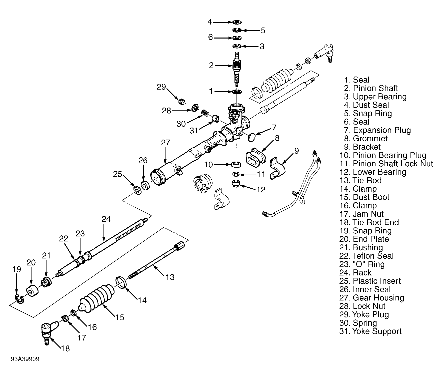
Hello and thank you for using 2carpros.com. To begin, to access the hoses, chances are you will need to loosen and lower the rack. Access to the hose is extremely limited and requires the gear to be loosened. Note: You referred to the damaged component as the "power tube". I am basing my reply on that meaning the high pressure hose which runs between the pump and the rack. If that is incorrect, please feel free to let me know. Additionally, I have attached a picture of the entire assembly for you to use when in process. It should help guide and indicate part locations and names. These directions are quite extensive, but it is the proper way to remove the gear assembly. If you have additional questions, please feel free to ask.
Thanks,
Joe
Secure radiator and fan shroud assembly to upper radiator support, using mechanics wire.
Remove oil level indicator, three exhaust heat shield bolts, and cooling tube nut. Position cooling tube bracket aside. Remove exhaust heat shield stud and shield.
Remove two engine intake air resonator nuts and bolt, loosen hose clamp from inlet tube, disconnect Mass Air Flow (MAF) sensor, and remove intake air resonator.
Remove four nuts retaining Three Way Catalytic (TWC) converter to manifold.
CAUTION: Since struts must be moved to remove halfshafts, struts must be loosened to prevent damage to strut piston rod.
Loosen left and right front shock absorber upper mounting nuts, five turns counterclockwise.
Support engine with Three Bar Engine Support 014-00750 (or equivalent).
Raise vehicle on hoist.
Remove front wheel assemblies.
Remove nine radiator air deflector screws and deflector.
Remove four bolts retaining left and right lower radiator support brackets to front of subframe. Turn brackets forward.
Remove two screws retaining bumper cover braces to left and right sides of subframe. Rotate braces forward.
Remove the two bolts retaining A/C accumulator to subframe.
Disconnect steering oil cooler hose clamps at right subframe, remove hoses, and drain power steering system.
Remove nuts from outlet flange on TWC converter and remove gasket.
Disconnect EGR valve tube fitting from TWC converter. Disconnect the Heated Oxygen Sensor (HO2S) connector pushpin from right subframe and disconnect H02S connector.
Loosen clamp from TWC converter assembly. Remove bracket nuts and bracket. Remove TWC converter assembly from rubber exhaust hanger and remove assembly.
Remove nut retaining steering cooler lines to right front of subframe. Remove two bolts retaining cooler lines to the rear of subframe.
Remove steering gear pinch bolt.
Lower vehicle.
Remove right and left pinch bolts and nuts from front wheel knuckles at lower arms.
Using Tie Rod End Remover TOOL-3290-D, disconnect left and right tie rod ends from front wheel knuckles.
If equipped, remove the ABS wiring harness from stabilizer bar link stud. Remove left and right front stabilizer bar link nuts from front strut assemblies. Disconnect both front stabilizer bar links from front strut assemblies.
Raise vehicle.
Remove through bolts retaining left and right front engine support insulators to the subframe.
Position Powertrain Lift 014-00765 or equivalent with wood blocks approximately 1016 mm (40 inches) in length, secured to lift under subframe.
Remove four subframe-to-body bolts.
Allow subframe to lower slightly. Disconnect steering pressure and return hoses from steering gear. Gently pry the lower control arms from steering knuckles and steering gear coupler from steering gear. Lower and remove subframe.
NOTE: Mark location of insulator prior to removing insulator from subframe for reference during installation.
Remove two rear insulator bolts and insulator.
Remove four remaining steering gear cover bolts and cover.
Remove two steering gear bolts and steering gear.
Installation
Position steering gear to subframe and install bolts. Tighten bolts to 137 N-m (101 lb-ft) .
Position steering gear cover and install bolts. Tighten bolts to 50 N-m (37 lb-in) .
Position rear insulator, align it with reference marks, and install bolts. Tighten bolts to 48 N-m (35 lb-ft) .
Replace old Teflon seals from steering pressure and return hose unions with new Teflon seals.
Lift and align subframe to body. Align left and right ball joints to knuckles and the position steering gear to steering column. Route steering pressure and return hoses into position at the rear of subframe. Securely install steering hoses. Install two bolts retaining cooler lines to rear of subframe. Securely tighten bolts. Install steering cooler line bracket and nut to right front of subframe.
Install subframe Alignment Pin Set T94P-2100-AH or equivalent into subframe. Install four subframe-to-body bolts. Tighten bolts to 130 N-m (96 lb-ft).
Lower and remove powertrain lift. Remove alignment tools from the subframe.
Observe left and right engine support insulators to make sure there is proper front-to-rear alignment. Install left and right engine support insulator through bolts. Tighten bolts to 120 N-m (89 lb-ft) .
Install steering column pinch bolt and tighten it to 23 N-m (17 lb-ft) .
Position front left and right bumper cover braces to the side of subframe and securely install bolts.
Position lower left and right radiator support brackets to subframe and install four bolts. Tighten bolts to 10 N-m (89 lb-ft) .
Securely install A/C accumulator bracket bolts to subframe.
Install new left and right ball joint pinch bolts and nuts. Tighten retainers to 83 N-m (61 lb-ft) .
Using a new exhaust converter inlet gasket, position TWC converter and loosely install two front nuts to exhaust manifold.
Using a new gasket, position muffler inlet to TWC converter outlet and loosely install nuts to outlet flange studs of TWC converter. Securely install EGR tube fitting. Tighten EGR tube nut to 25 N-m (18 lb-ft) .
Position exhaust system on rubber exhaust hanger. Tighten muffler inlet flange nuts to 40 N-m (30 lb-ft) . Position converter bracket to engine bracket and install nuts. Install lower bracket clamp nuts. Tighten all four nuts to 25 N-m (18 lb-ft) .
Press TWC converter against the exhaust manifold and tighten converter clamp bolt to 25 N-m (18 lb-ft) . Connect HO2S connector and install HO2S connector pushpin to subframe.
Install steering cooler hoses to cooler and install clamps.
Position front air deflector and install screws.
Lower vehicle.
Connect left and right stabilizer bar links to front struts, install nuts, and tighten them to 47 N-m (35 lb-ft) . If equipped, install ABS wiring harness to stabilizer bar link stud.
Connect left and right tie rod ends to front wheel knuckles. Install tie rod end nuts. Tighten nuts to 31 N-m (23 lb-ft) , then continue to nearest cotter pin slot and insert new cotter pins.
Lower vehicle.
Remove three bar engine support.
Remove mechanics wire retaining radiator to upper support.
Tighten left and right front strut upper mounting nuts to 46 N-m (34 lb-ft) .
Install two remaining TWC converter exhaust nuts. Tighten nuts to 40 N-m (30 lb-ft) .
Position exhaust heat shield, coolant tube, and hose retainers. Install three heat shield bolts and one stud. Tighten retainers to 10 N-m (89 lb-ft) . Position A/C hose bracket to stud, securely install nut, and insert oil level indicator.
Install engine intake air resonator, one bolt, and two nuts. Connect MAF sensor and securely tighten hose clamp to inlet tube.
Fill power steering system.
Install front wheel assemblies.
Lower vehicle.
Check operation of system.
May 3, 2018 at 6:23 PM