Power steering line leaking

Tiny
NAIL4MULA
  • MEMBER
  • 2003 TOYOTA CELICA
  • 1.8L
  • 4 CYL
  • 2WD
  • MANUAL
  • 90,000 MILES
The power steering line connecting power steering pump to steering shaft is leaking. I suppose it is the high pressure line since fluid is leaking out really fast. Is it dangerous to drive without power steering? Is it better to change two lines, even when it is the high pressure that is leaking? Can I raise the front end of the car with a hydraulic jack?
Sunday, October 21st, 2018 AT 7:38 PM

12 Replies

Tiny
JACOBANDNICKOLAS
  • MECHANIC
  • 108,192 POSTS
Hi and thanks for using 2CarPros. Com.

If the power steering fluid runs out, it will damage the pump. So, you really should not drive it until the line is fixed. The front can be lifted with a jack, but make sure to place the jack in a designated lift point so you do not damage anything. Also, use a jack stand to make sure the vehicle cannot fall. Hydraulics can fail. And yes, replace both so you do not have to deal with it again in the near future.

Let me know if you have other questions.

Take care,
Joe
Was this
answer
helpful?
Yes
No
+1
Sunday, October 21st, 2018 AT 7:58 PM
Tiny
NAIL4MULA
  • MEMBER
  • 11 POSTS
Hi Joe,

Thank you for the answers. After raising the car with the hydraulic jack and securing with jack stands, I realised the difficulty of reaching these lines. Can you give me a step by step procedure to replace these power steering lines?
Was this
answer
helpful?
Yes
No
Wednesday, October 24th, 2018 AT 7:39 AM
Tiny
JACOBANDNICKOLAS
  • MECHANIC
  • 108,192 POSTS
Hi and welcome back. Yes, this isn't an easy one. If the steering gear needed replaced, you would need to lift the engine. Ugh!

Here are the directions. I feel they are vague, but this is what the manual provides. All attached pictures correlate with these directions.

REMOVAL
1. REMOVE RH AND CENTER ENGINE UNDER COVERS
2. REMOVE DRIVE BELT
Loosen the drive belt tension by turning the drive belt tensioner arm clockwise, and remove the drive belt.
3. DISCONNECT SUCTION HOSE
Remove the clip and disconnect the suction hose.

NOTICE: Take care not to spill fluid on the drive belt.

4. DISCONNECT PRESSURE FEED TUBE
a. Using SST, disconnect the pressure feed tube.
SST 09023-38400
b. Remove the bolt and disconnect the pressure feed tube clamp.

___________________________

At steering gear

1. Place front wheels facing straight ahead.
2. Remove RH, center, and LH engine under covers.
3. Disconnect pressure feed and return tubes.
Using SST, disconnect the pressure feed and return tubes.
SST 09023-38400

______________________________________________________

I hope this helps. Let me know if you run into trouble.

Take care,
Joe
Was this
answer
helpful?
Yes
No
Wednesday, October 24th, 2018 AT 5:57 PM
Tiny
NAIL4MULA
  • MEMBER
  • 11 POSTS
Thank you Joe. It turns out that the problem is a leak of the small pipe, which is part of the rack and pinion. Can I change it or fix it? What are the steps to remove and replace the whole rack and pinion?
Was this
answer
helpful?
Yes
No
Friday, July 19th, 2019 AT 6:18 PM
Tiny
JACOBANDNICKOLAS
  • MECHANIC
  • 108,192 POSTS
Okay, it's one of the steel lines on the rack. You may be able just to replace that steel line. However, here are the directions for rack replacement. The attached pictures correlate with the directions.

_________________________________________________

Removal and Installation
Vehicle Steering and Suspension Steering Steering Gear Service and Repair Procedures Removal and Installation
REMOVAL AND INSTALLATION
Part 1 Of 3

pic 1

Part 2 Of 3

pic 2

Part 3 Of 3

pic 3

REMOVAL

NOTICE: Remove the steering wheel assembly before the steering gear removal, because there is possibility of breaking of the spiral cable.

1. PLACE FRONT WHEELS FACING STRAIGHT AHEAD
2. REMOVE STEERING WHEEL PAD
3. REMOVE STEERING WHEEL
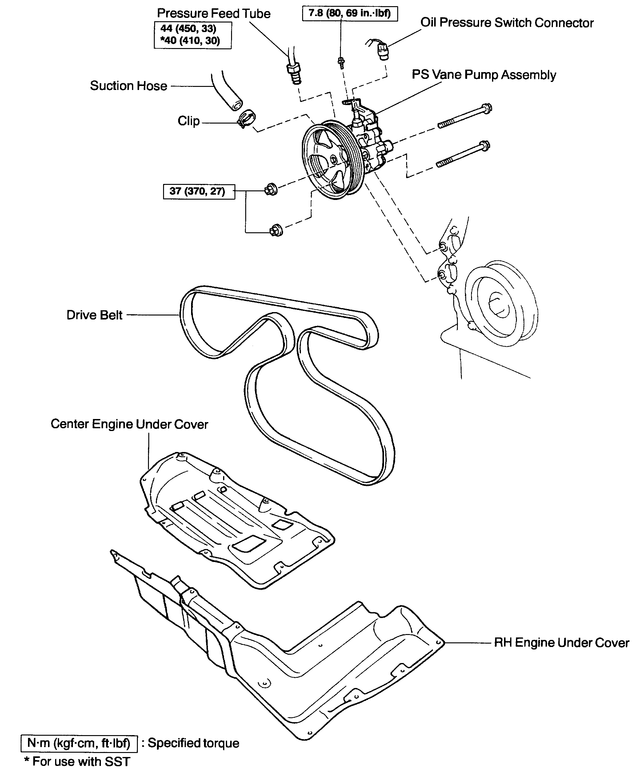
4. REMOVE RH, CENTER AND LH ENGINE UNDER COVERS
5. DISCONNECT RH AND LH TIE ROD ENDS
6. DISCONNECT NO. 2 INTERMEDIATE SHAFT ASSEMBLY

pic 4

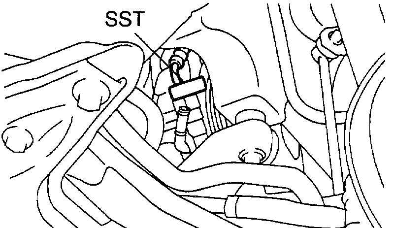
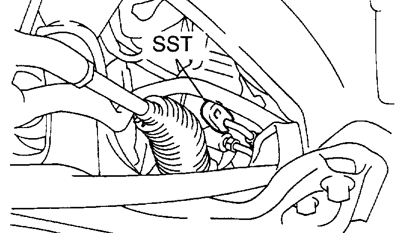
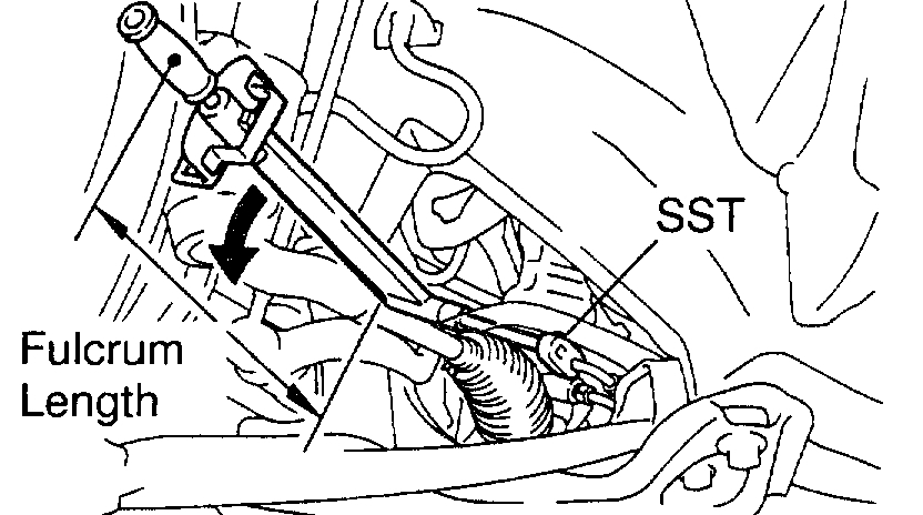
7. DISCONNECT PRESSURE FEED AND RETURN TUBES
Using SST, disconnect the pressure feed and return tubes.
SST 09023-38400

pic 5

8. DISCONNECT TUBE CLAMP
Remove the bolt and disconnect the tube clamp.
9. DISCONNECT COLUMN HOLE COVER ASSEMBLY
10. REMOVE ENGINE HOOD

pic 6

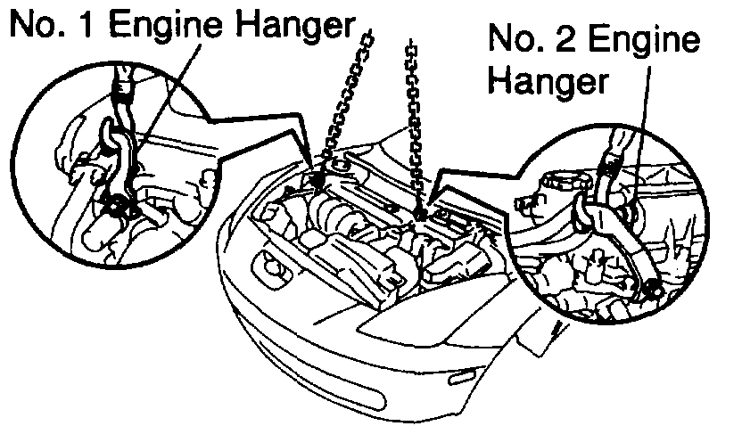
11. ATTACH ENGINE SLING DEVICE TO ENGINE HANGERS
a. Remove the 4 bolts and No. 2 cylinder head cover.
B. Disconnect the PCV hoses from the cylinder head cover.
C. Install the No.1 and No. 2 engine hangers in the correct direction.
1Z-FE Engine: Part No:
No.1 engine hanger: 12281-22021
No.2 engine hanger: 12281-15040 or 12281-15050
Bolt: 91512-B1016
Torque: 38 Nm (388 kgf-cm, 28 ft. Lbs.)
2ZZ-FE Engine:
Part No:
No.1 engine hanger: 12281-88600
No.2 engine hanger: 12282-88600
Bolt: 91512-61020
Torque: 38 Nm (388 kgf-cm, 28 ft. Lbs.)
d. Attach the engine sling device to the engine hangers.

CAUTION: Do not attempt to hang the engine by hooking the chain to any other part.

12. DISCONNECT LOWER BALL JOINT FROM LOWER SUSPENSION ARM
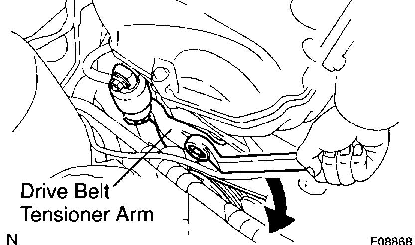
13. DISCONNECT STABILIZER BAR
a. Remove the nut and disconnect the stabilizer bar.
B. Employ the same manner described above to the other side.

Pic 7

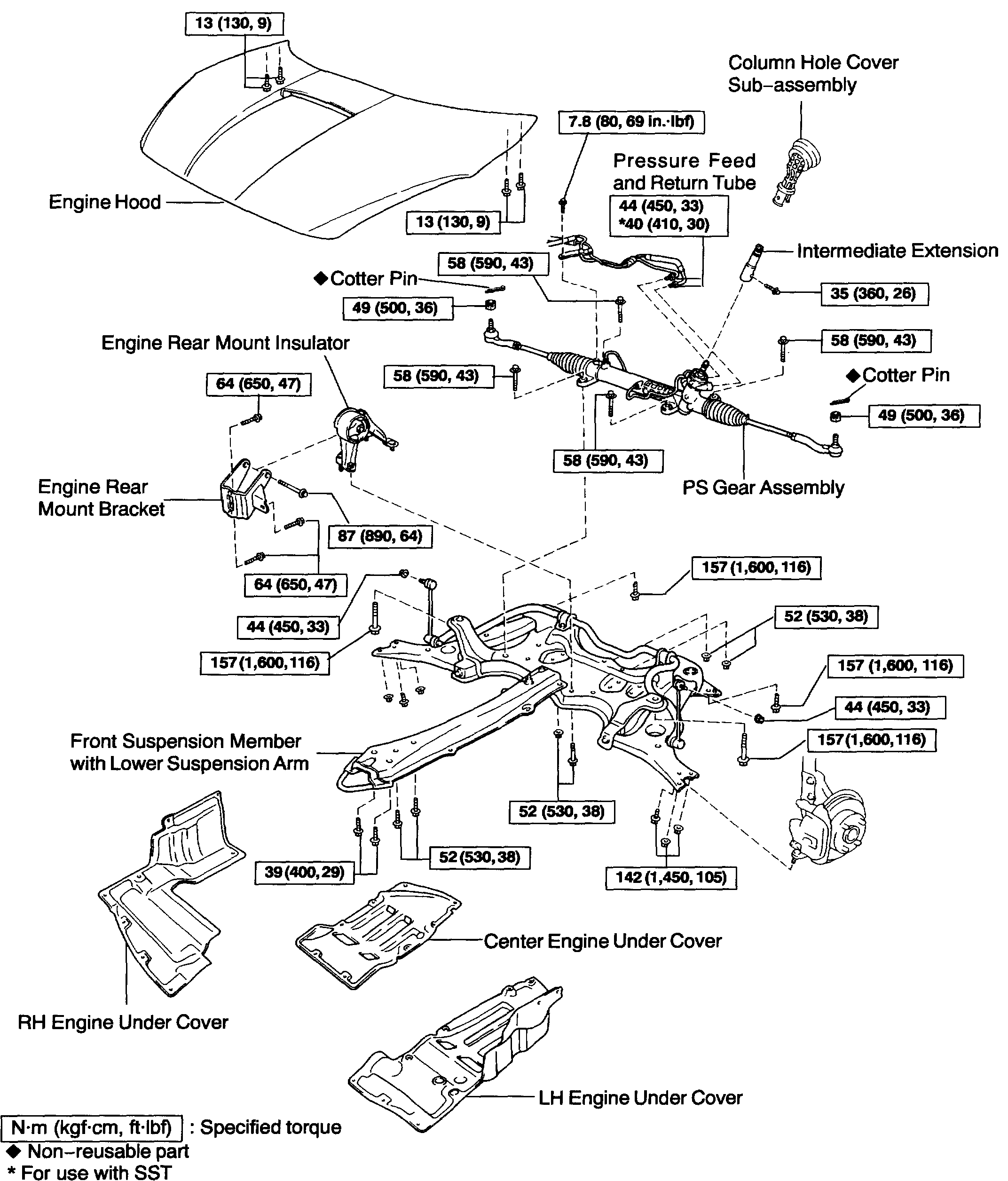
14. DISCONNECT ENGINE REAR MOUNT INSULATOR AND FRONT SUSPENSION MEMBER
Remove the bolt (bolt A) and 3 nuts, and disconnect the engine rear mount insulator and front suspension member.
15. DISCONNECT ENGINE FRONT MOUNT INSULATOR AND FRONT SUSPENSION MEMBER
Remove the 2 bolts (bolt B) and disconnect the engine front mount insulator and front suspension member.
16. SUPPORT FRONT SUSPENSION MEMBER WITH LOWER SUSPENSION ARM
Using a transmission jack, support the front suspension member with lower suspension arm.
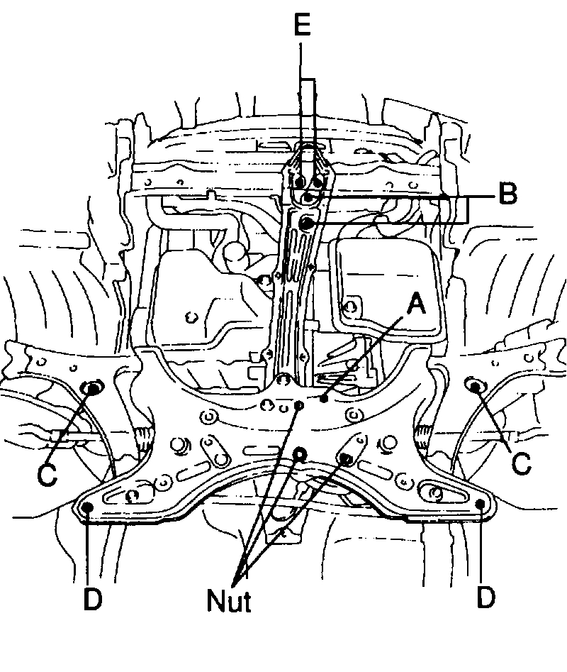
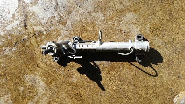
17. REMOVE FRONT SUSPENSION MEMBER WITH LOWER SUSPENSION ARM AND PS GEAR ASSEMBLY
Remove the 6 bolts (bolt C, D and E) and front suspension member with lower suspension arm and PS gear assembly.

Pic 8

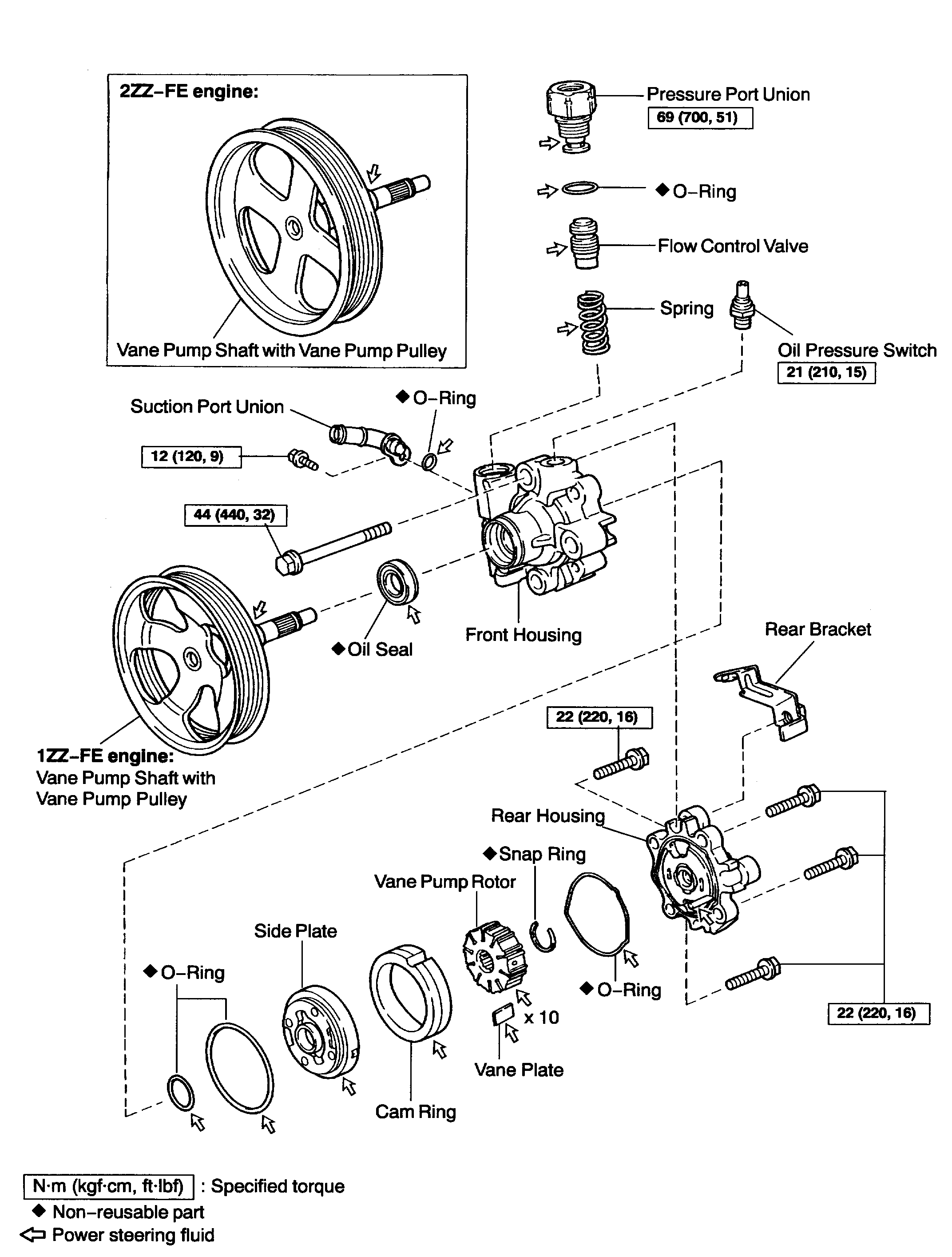
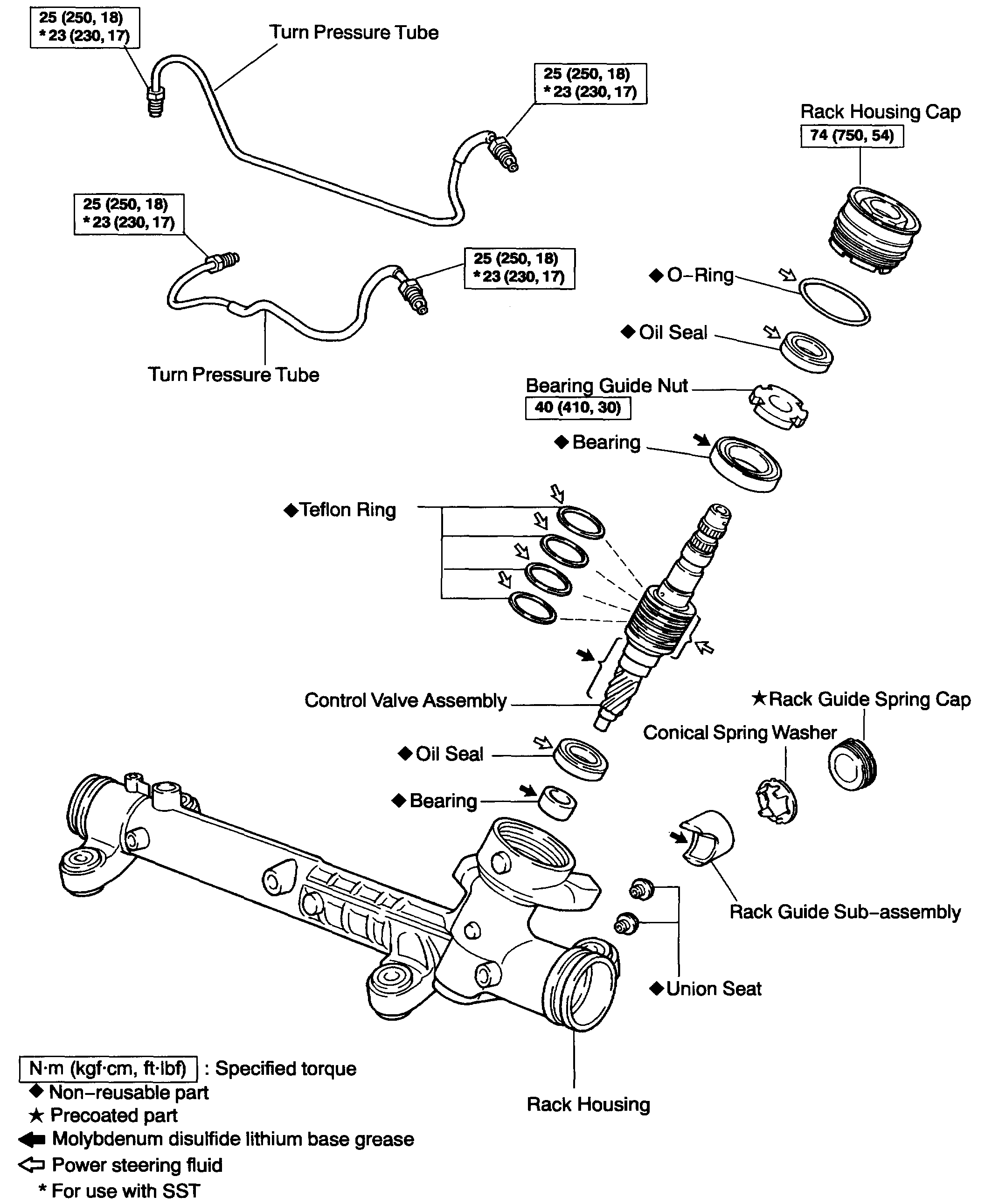
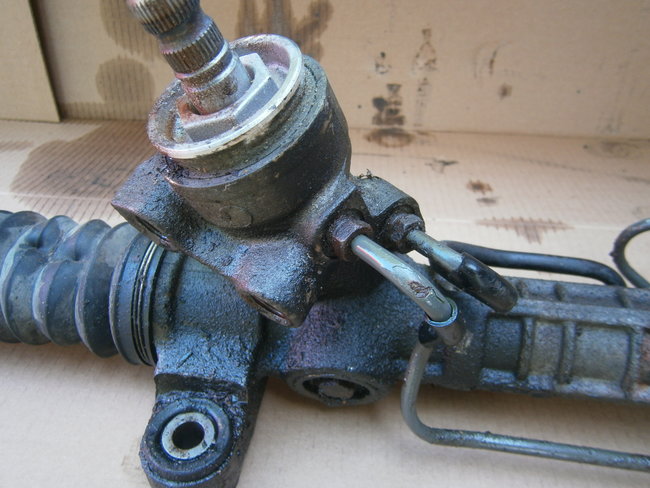
18. REMOVE PS GEAR ASSEMBLY
a. Remove the 4 bolts and PS gear assembly from the front suspension member.
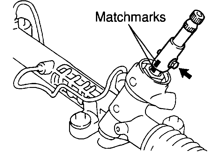
B. Place matchmarks on the intermediate extension and control valve shaft.
C. Remove the bolt and intermediate extension.
19. REMOVE ENGINE REAR MOUNT INSULATOR AND ENGINE REAR MOUNT BRACKET
a. Remove the through bolt and engine rear mount insulator.
B. Remove the 3 bolts and engine rear mount bracket.

INSTALLATION
1. INSTALL ENGINE REAR MOUNT INSULATOR AND ENGINE REAR MOUNT BRACKET
a. Install the engine rear mount bracket with the 3 bolts.
Torque: 64 Nm (650 kgf-cm, 47 ft. Lbs.)
b. Install the engine rear mount insulator with the through bolt.
Torque: 87 Nm (890 kgf-cm, 64 ft. Lbs.)

pic 9

2. INSTALL PS GEAR ASSEMBLY
a. Align the matchmarks on the intermediate extension and control valve shaft.
B. Install the bolt.
Torque: 35 Nm (360 kgf-cm, 26 ft. Lbs.)
c. Install the PS gear assembly with the 4 bolts to the front suspension member.
Torque: 58 Nm (590 kgf-cm, 43 ft. Lbs.)

pic 10

3. INSTALL FRONT SUSPENSION MEMBER WITH LOWER SUSPENSION ARM AND PS GEAR ASSEMBLY
Install the front suspension member with lower suspension arm and PS gear assembly with the 6 bolts (bolt C, D and E).
Torque:
Bolt C: 157 Nm (1,600 kgf-cm, 116 ft. Lbs.)
Bolt D: 157 Nm (1,600 kgf-cm, 116 ft. Lbs.)
Bolt E: 39 Nm (400 kgf-cm, 29 ft. Lbs.)
4. CONNECT ENGINE FRONT MOUNT INSULATOR AND FRONT SUSPENSION MEMBER
Connect the engine front mount insulator and front suspension member with the 2 bolts (bolt B).
Torque: 52 Nm (530 kgf-cm, 38 ft. Lbs.)
5. CONNECT ENGINE REAR MOUNT INSULATOR AND FRONT SUSPENSION MEMBER
Connect the engine rear mount insulator and front suspension member with the bolt (bolt A) and 3 nuts.
Torque: 52 Nm (530 kgf-cm, 38 ft. Lbs.)
6. CONNECT STABILIZER BAR
a. Connect the stabilizer bar with the nut.
Torque: 44 Nm (450 kgf-cm, 33 ft. Lbs.)
b. Employ the same manner described above to the other side.
7. CONNECT LOWER BALL JOINT TO LOWER SUSPENSION ARM

pic 11

8. DISENGAGE ENGINE SLING DEVICE FROM ENGINE HANGERS
a. Disengage the engine sling device from the engine hangers.
B. Remove the No. 1 and No. 2 engine hangers.
C. Connect the PCV hoses to the cylinder head cover.
D. Install the No. 2 cylinder head cover with the 4 bolts.
9. INSTALL ENGINE HOOD
10. CONNECT COLUMN HOLE COVER SUB-ASSEMBLY

pic 12

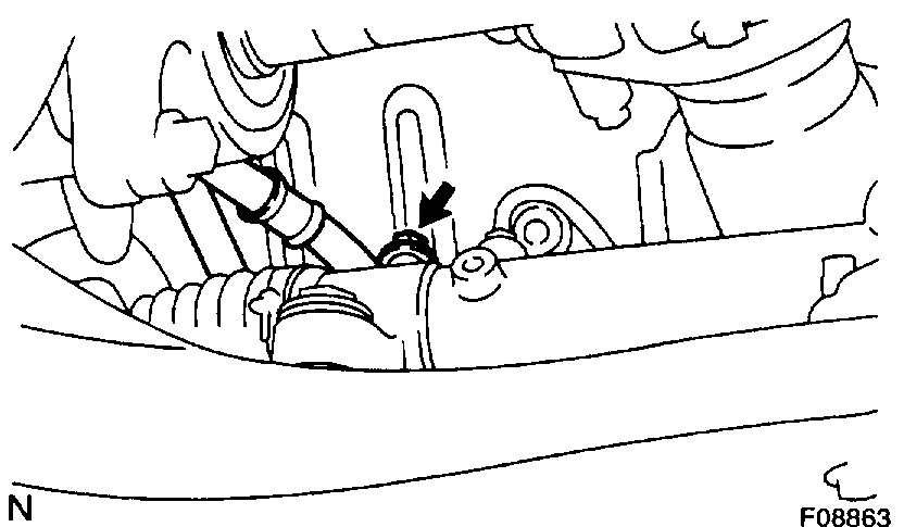
11. CONNECT TUBE CLAMP
Connect the tube clamp with the bolt.
Torque: 7.8 Nm (80 kgf-cm, 69 inch lbs.)

pic 13

12. CONNECT PRESSURE FEED AND RETURN TUBES
Using SST, connect the pressure feed and return tubes.
SST 09023-38400
Torque: 40 Nm (410 kgf-cm, 30 ft. Lbs.)

HINT:
Use a torque wrench with a fulcrum length of 345 mm (13.58 inch).
This torque value is effective in case that SST is parallel to a torque wrench.

13. CONNECT NO. 2 INTERMEDIATE SHAFT ASSEMBLY
14. CONNECT RH AND LH TIE ROD ENDS
15. INSTALL RH, CENTER AND LH ENGINE UNDER COVERS
16. PLACE FRONT WHEELS FACING STRAIGHT AHEAD

HINT: Do it with the front of the vehicle jacked up.

17. CENTER SPIRAL CABLE
18. INSTALL STEERING WHEEL
a. Align the matchmarks on the steering wheel and steering column main shaft.
B. Temporarily tighten the steering wheel set nut.
19. BLEED POWER STEERING SYSTEM
20. CHECK STEERING WHEEL CENTER POINT
21. TORQUE STEERING WHEEL SET NUT
Torque: 50 Nm (510 kgf-cm, 37 ft. Lbs.)
22. INSTALL STEERING WHEEL PAD
23. CHECK FRONT WHEEL ALIGNMENT

+++++++++++++++++++++++++++++++++++++++++++++++++++++++++++++++

Let me know if this helps.

Take care,
Joe
Was this
answer
helpful?
Yes
No
+1
Friday, July 19th, 2019 AT 7:14 PM
Tiny
NAIL4MULA
  • MEMBER
  • 11 POSTS
Thank you Joe. It's been very helpful. I saw the film on the internet about replacement of rack & pinion on Toyota Camry, without removing steering wheel assembly, the engine hood nor the steps in points 13-17 and thought that a similar procedure could be followed on my car. Given the complexity and tools required to perform the replacement of rack & pinion, I will leave it to a mechanic.
Was this
answer
helpful?
Yes
No
Monday, July 22nd, 2019 AT 11:51 AM
Tiny
NAIL4MULA
  • MEMBER
  • 11 POSTS
Joe, I have another question. Can I just replace the drive belt with the shorter one to bypass the pomp and continue driving without power steering? If yes, please specify the part number.
Was this
answer
helpful?
Yes
No
Monday, July 22nd, 2019 AT 5:11 PM
Tiny
JACOBANDNICKOLAS
  • MECHANIC
  • 108,192 POSTS
Welcome back:

You can do it, but it's really not recommendable. The rack is designed to have fluid pumped to it for assist. Also, the belt size would have to be measured. I just looked at the belt routing for your vehicle. Truly, I don't see how it could work. If you remove the PS pump from the design, there is nothing for the tensioner to maintain pressure against. I highlighted the tensioner in the below pic.

I really feel it needs to be repaired. Can you tell me where exactly it is leaking? Is it coming from the line between the rack and the pump? Is it the steel equalization line on the rack? Is it leaking from the boots at the end of each side of the rack?

Let me know.

Joe
Was this
answer
helpful?
Yes
No
+1
Tuesday, July 23rd, 2019 AT 7:39 PM
Tiny
NAIL4MULA
  • MEMBER
  • 11 POSTS
Thank you Joe.
It is the steel line on the rack that is leaking. I got the image from the internet and added the arrow at the exact spot where it is leaking. Can it be repaired without taking out rack and pinion?
Was this
answer
helpful?
Yes
No
Wednesday, July 24th, 2019 AT 2:14 PM
Tiny
JACOBANDNICKOLAS
  • MECHANIC
  • 108,192 POSTS
It is going to be tight, but I would give it a try. You may have to just disconnect the existing one and reroute a new one. However, have you checked to make sure it is tight? It may have worked itself loose from time and miles.

Let me know.

Joe
Was this
answer
helpful?
Yes
No
+1
Wednesday, July 24th, 2019 AT 11:18 PM
Tiny
NAIL4MULA
  • MEMBER
  • 11 POSTS
Hi Joe,
Thank you for your answers. I thought of a possibility to repair the hole on steel line without removing the whole rack and pinion but couldn't find a way to do it. There was no way to change the steel line on the rack without removing it first. After removing the rack and pinion, the garage would not change just the line, because of the warranty on the job. Even if they agreed to change just the line, the savings would be negligible comparing to the cost of labor for replacing the rack and pinion. So finally I have decided to have it replaced with the reconditioned unit. I attach the picture of the rack where you can clearly see the steel line with small rust dent and (which you cannot see) little hole(s). For now it works well, I hope it will last at least 5 years to justify the expenditure.
Was this
answer
helpful?
Yes
No
Thursday, August 1st, 2019 AT 7:57 AM
Tiny
JACOBANDNICKOLAS
  • MECHANIC
  • 108,192 POSTS
Welcome back and you are very welcome. I see where it must have been leaking and it would have been tough to repair. Regardless, I'm glad you got it back together and it's working good for you.

If you ever have questions or need help in the future, I hope you come back.

Take care,

Joe
Was this
answer
helpful?
Yes
No
+1
Thursday, August 1st, 2019 AT 7:15 PM

Please login or register to post a reply.

Sponsored links