Power seat opposite operation

Tiny
BK BARR
  • MEMBER
  • 2003 CHRYSLER VOYAGER
  • 2.4L
  • 4 CYL
  • 2WD
  • AUTOMATIC
  • 105,000 MILES
I got 2 front power seats from a Pick and Pull van (maybe a Dodge Grand Caravan (about the same year as my van). I was determining of they worked, so I hooked the passenger seat up to a power source and things didn't go as expected. Specifically, + to + and - to - don't result in any movement, in fact, the power source (a Type S, jump starter (Costco)) complained. When I reversed the polarity, the seat worked in all directions, but in a direction opposite of what the side seat switch was indicating. I did not get the memory module when I was at Pick and Pull.

They grey connector under the seat has two wires that are larger than the others orange/red (+) and black/orange (-). When powered this way the seat does not work, but when orange/red is (-) etc, the seat moves.

I have only tried the passenger seat so far.

So please. Let me know why this is occurring. Also, when this gets sorted should I power these to something that's always hot, and should the sets be wired on the same fuse (20A)?

Thanks
BK
Friday, December 18th, 2020 AT 1:44 PM

9 Replies

Tiny
CARADIODOC
  • MECHANIC
  • 33,741 POSTS
Orange/red (+) and black/orange (-) is correct, but first of all, are you adding power seats to your van or replacing something? Does your van and/or the donor van have memory seats?

These are the two diagrams for without memory seats. It sounds like you had them connected correctly the first time. It looks like memory seats have to be used with the module. At least the wire colors are different. I'm working on preparing those in case you need me to post them.

I'm getting error messages when trying to post the diagrams. For some reason they showed up further down on the next reply.
Was this
answer
helpful?
Yes
No
Friday, December 18th, 2020 AT 2:17 PM
Tiny
BK BARR
  • MEMBER
  • 4 POSTS
The car has manual everything (except transmission). While cruising in the van area at PNP I came across a Dodge product that had been in a horrible wreck and yet its front seats were unscathed. So, when I had the chance I took them out. I figured that they'd go nice in my recently purchased salvaged Voyager. I do have an Alldata account for this car.

I'm not sure what year or model of van that I pulled these seats from, only that it was a Chrysler product. The donor car is probably gone now, but the memory module was not accessible on the wrecked van; that's where one of the main impacts occurred. Right now, I'd like to move forward and save the memory module for another days adventure.

Any tips on how I could get these seats to work correctly without the memory module? I don't know if the wires of the switch can be reversed so that the seat(s) will work as intended.

I didn't receive another email with pictures, but any help offered is appreciated.

Thanks!
BK
Was this
answer
helpful?
Yes
No
Friday, December 18th, 2020 AT 3:11 PM
Tiny
CARADIODOC
  • MECHANIC
  • 33,741 POSTS
Here's the diagrams again.
Was this
answer
helpful?
Yes
No
Friday, December 18th, 2020 AT 5:39 PM
Tiny
CARADIODOC
  • MECHANIC
  • 33,741 POSTS
Part of the problem is I put apostrophes in the titles for the saved diagrams, and one of the computers didn't know what to do with them.

If you can't read them, there's two ways to solve that. One is I can cut them into two parts, then enlarge them and repost them. If you need them before I get back here tomorrow, you can copy and paste them into an MS Word typing program, then select 150 or 200 percent to make the pages bigger. These are from AllData, so you can find them there too.

I'm going to need some time to compare the diagrams and see what it will take to get these seats working. I'll work on that tonight at home. As for a motor running the wrong way, for a custom job, that can be solved by pulling the two wires out of one half of the connector, and switching their locations. That switching of polarity is normally done with the switches. I don't think it will come to that.

When you got the seats, did you snip off the vehicle-side of the connectors with a few inches of wire, or did you just unplug them and leave the connectors behind?
Was this
answer
helpful?
Yes
No
Friday, December 18th, 2020 AT 5:39 PM
Tiny
CARADIODOC
  • MECHANIC
  • 33,741 POSTS
Here's the diagrams again.

Update: I don't know why this reply insists on showing up at the bottom over and over. Just disregard it. Things will be working normally again tomorrow.
Was this
answer
helpful?
Yes
No
+1
Friday, December 18th, 2020 AT 5:44 PM
Tiny
BK BARR
  • MEMBER
  • 4 POSTS
Thanks!
Was this
answer
helpful?
Yes
No
Friday, December 18th, 2020 AT 8:02 PM
Tiny
CARADIODOC
  • MECHANIC
  • 33,741 POSTS
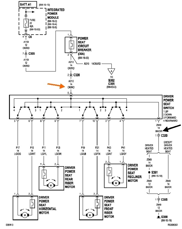
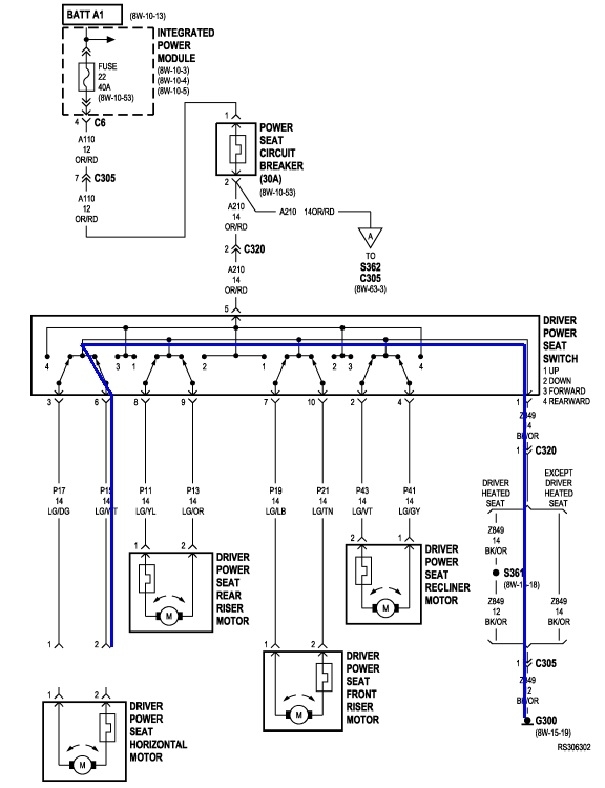
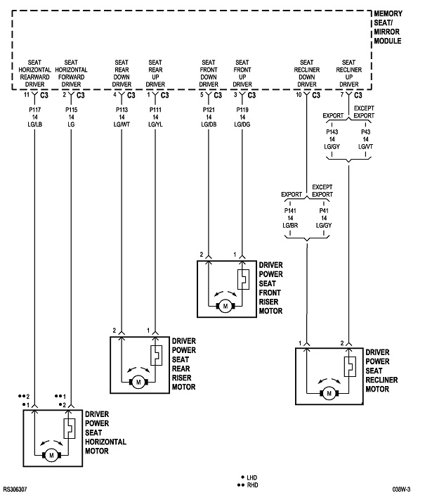
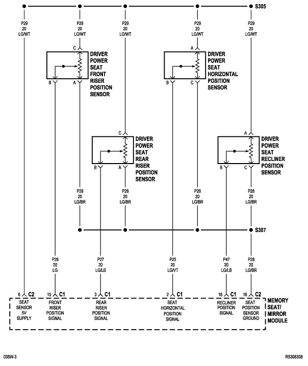
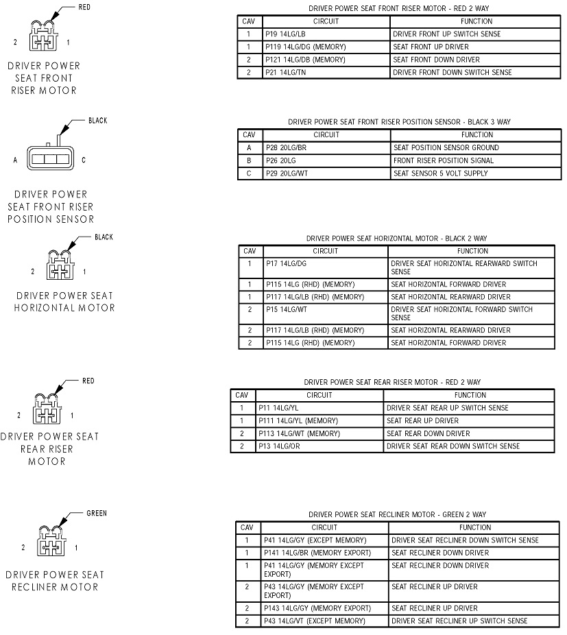
I see why your seat motors are running backward. This first diagram is for the driver's seat that I posted previously. There's four totally independent circuits. The only thing they have in common is all the switches are inside one giant switch assembly. The next thing is there's a switch for each of the two motor's wires. Note that there's no dashed line connecting the two switches for the Driver's power seat horizontal motor. That means the two switches operate independently of each other. In fact, the button is designed to activate only one switch at a time.

The next observation of value has to do with the circuitry itself. If you care to prove this for yourself, you must unplug the motor. This also applies to diagnosing a dead motor. During continuity tests, the motor ties the two circuits together. If one of them has a break, whether a wire is broken between the door hinges, or a switch has burned contacts, continuity will be read through the motor, then through the second circuit. Unplugging the motor isolates the two circuits from each other so each one can be tested independently.

Diagram 2

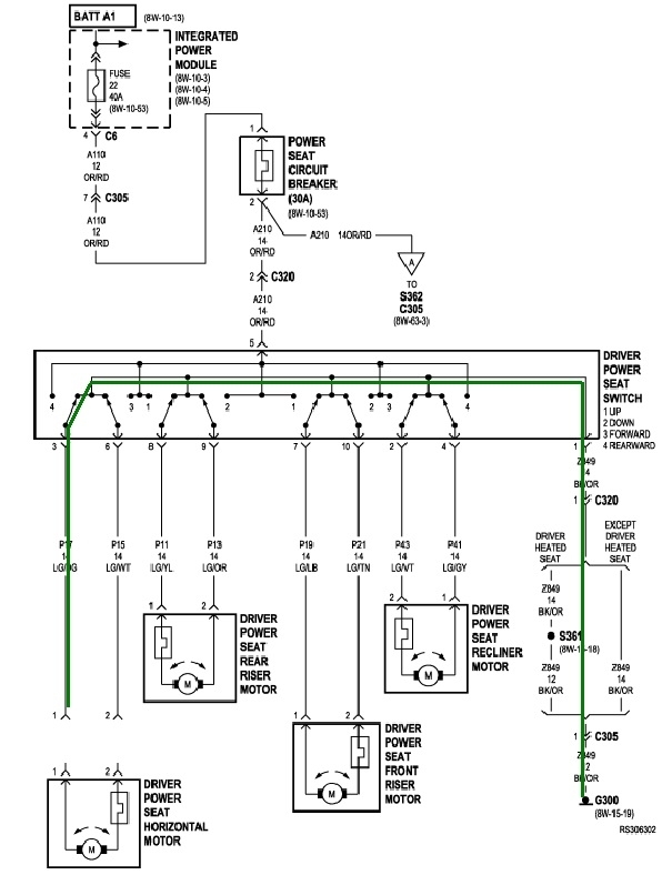
Now that the motor is unplugged, check the continuity from one of the wires in that plug, to ground. The current path is shown with the green line. All of the switches are released. You should find very low resistance, in the order of around five ohms or less.

Diagram 3

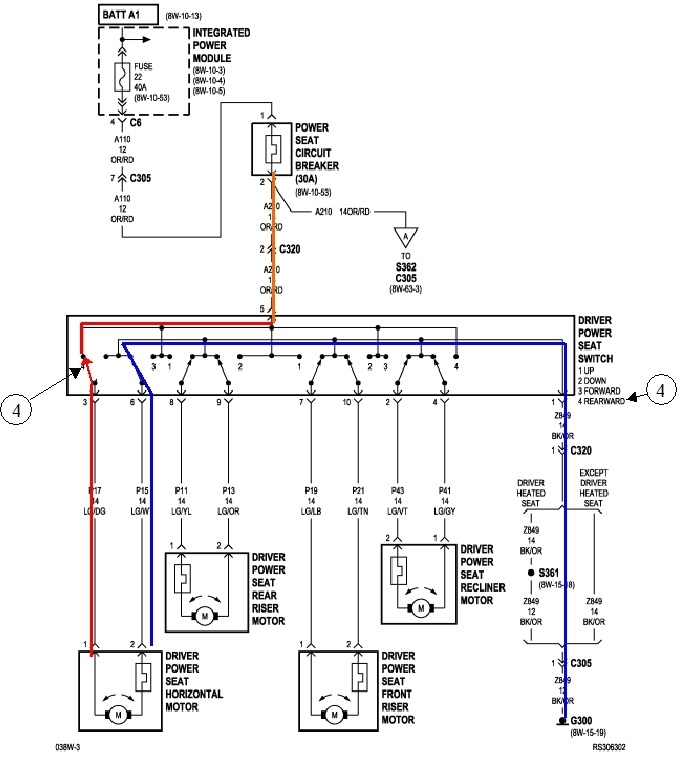
In the third diagram, the second circuit is being tested. The blue line shows that this circuit is also grounded through the released switch. The other three motors use identical circuits and are tested the same way.

Diagram 4

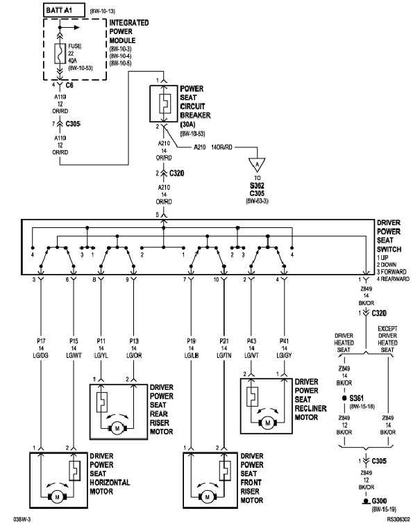
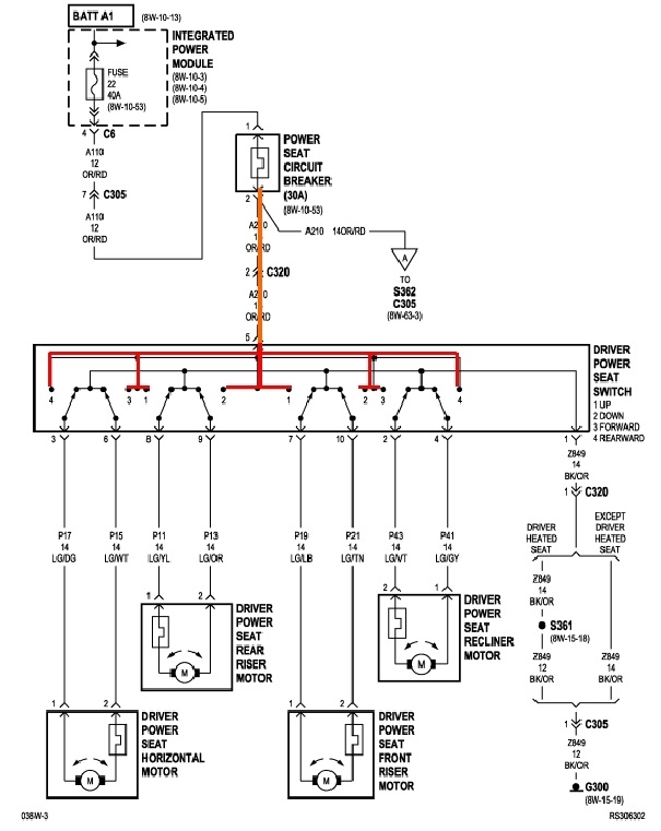
To diagnose this circuit, there is just one wire that will have 12 volts. That's shown with the orange line. Once inside the switch, that 12 volts follows the red lines to four switch contacts, but it stops there when the switches are released. The important point is that other than that one orange wire, every other terminal on the switch assembly will read continuity to ground.

Diagram5

Here the horizontal switch has been pressed for the rear direction. The far left switch has been switched away from ground and has made the connection to the 12 volt contact. That puts 12 volts on one of the motor's terminals. Nothing has changed on the other motor's wire so it's still grounded. The motor runs the seat rearward.

Likewise, if that switch is pressed for the forward direction, the switch in the red circuit goes back to ground, and this time the switch in the blue circuit moves from ground to its 12-volt contact. This puts the 12 volts on the motor's other wire. Polarity is reversed, so the motor runs the other way.

Before the engineers forgot how to design these circuits without needing a computer, power windows and power mirrors worked the same way. This type of switching works for any motor that needs to run both ways at different times.

Diagrams 6 and 7

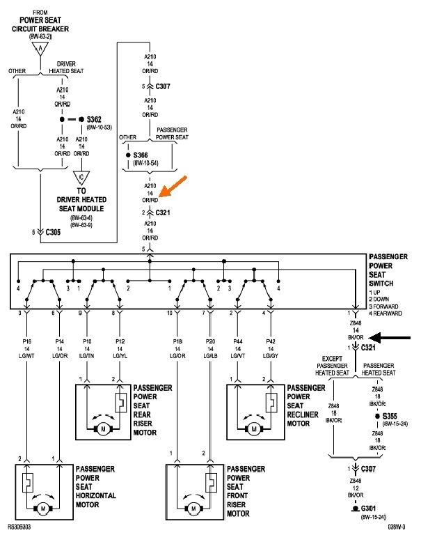
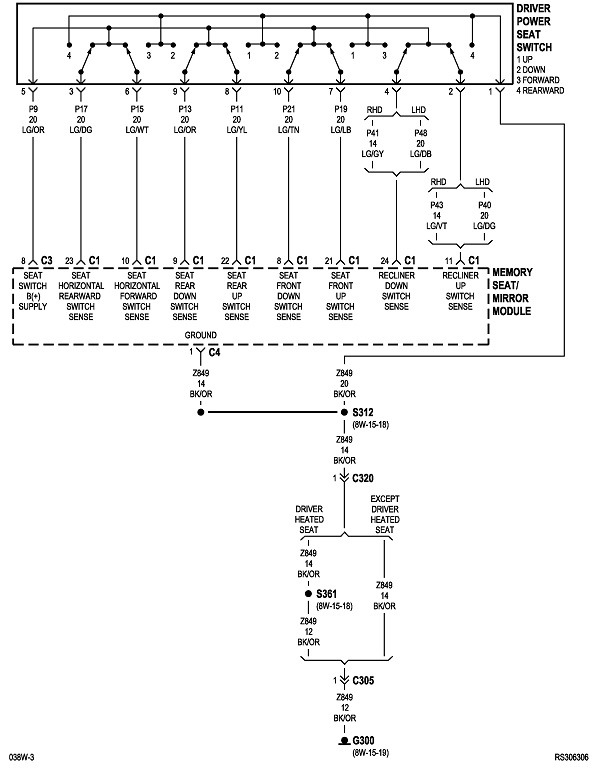
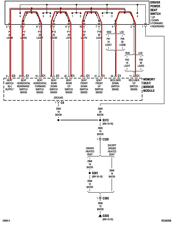
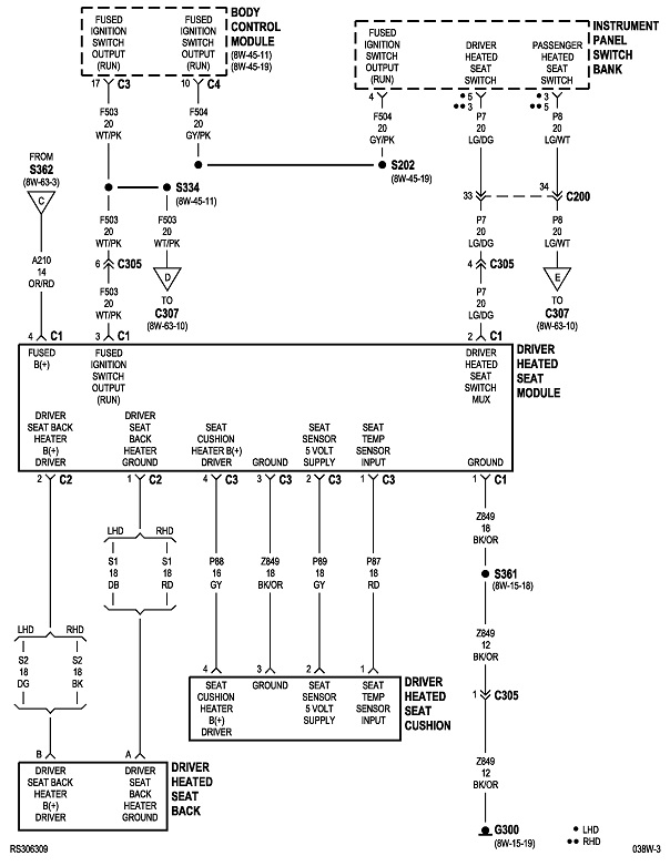
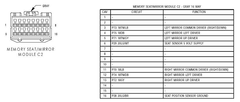
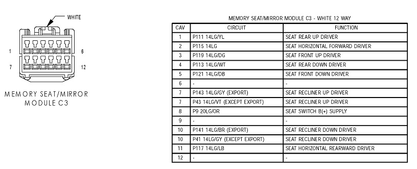
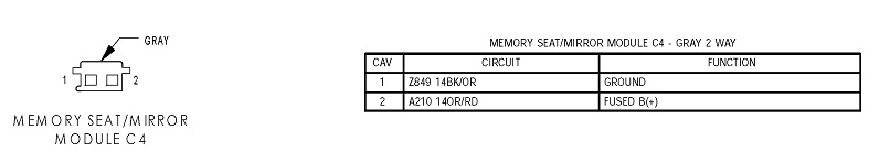
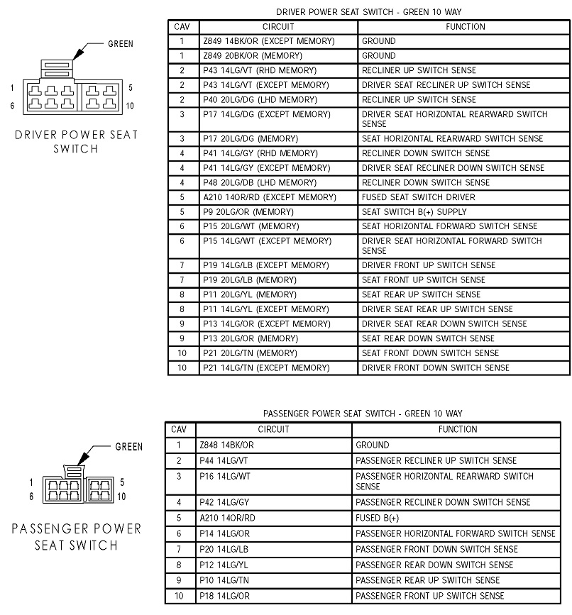
These diagrams are for the driver's seat with memory. At first the switch assembly looks the same, but instead of turning motor current on and off, they are inputs to the Memory Computer, then the switching circuits are inside that computer. The wire colors are different, but their functions are the same as with the non-memory system.

Diagram 8

Remember that previously all of the motor wires were grounded when the switches were released. Here, in the memory system, they did it just the opposite. The red lines show that the 12-volts is fed to all of the switches. When a function is selected, the switch breaks the circuit to the 12-volt supply, then it grounds that wire. Going to 0 volts is what signals the computer to switch one of that motor's wires. What isn't clear here is whether the motor wires will have 12 volts or 0 volts on both when nothing is being activated.

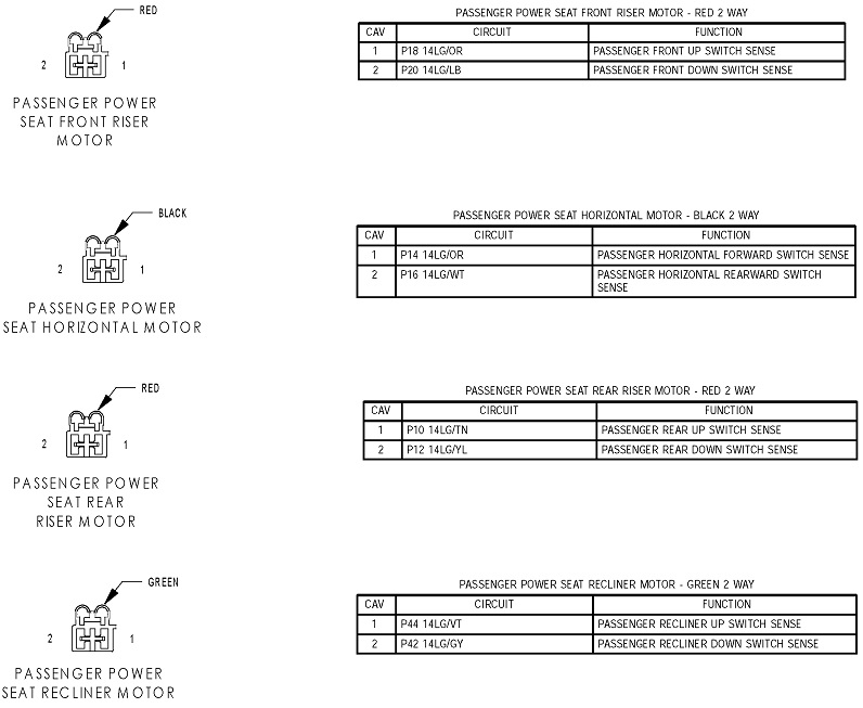
I suspect you're going to have to find switches in the salvage yard from power seats without the memory feature. Those have to handle the full motor current which could be around five amps. In the memory system, the switches only have to pass a small fraction of an amp to send signals to the computer. As evidence of this, look at the wire designations for the motors on diagram 1. The first one for the driver's horizontal motor is "P17 14 LG / DG". That's circuit P17, 14 gauge, light green with a dark green tracer, or stripe. Fourteen gauge wires can handle up to 15 amps. They wouldn't use wires that large and expensive if they weren't needed.

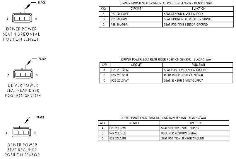
Now look at the wires in diagrams 7 and 8. The motor wires are still 14 gauge, but for the switches, they're all 20 gauge wires. Those are among the smallest-diameter wires used in cars. They can't handle five amps. To save money, when the switches don't have to handle much current, they're not going to use switches rated higher than necessary. I suspect what you have now is not going to hold up if they're wired directly to the motors.

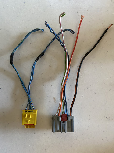
You should be able to harvest the correct switch assemblies along with the wires under the seats from a van that didn't have memory seats. Take along some masking tape to label the plugs so you don't have to waste time figuring out which plug goes to which motor. The motors are usually interchangeable which means the connectors will be the same, and therefore can be mixed up. With those harnesses, there should be just a ground wire and a 12-volt feed for each seat. Let me know if you need help with the wire colors.
Was this
answer
helpful?
Yes
No
Saturday, December 19th, 2020 AT 3:06 PM
Tiny
BK BARR
  • MEMBER
  • 4 POSTS
Yes, I did take the wiring harness (about 6") from the car side of the seat wiring. This was where I applied power to the seat. Thanks for your input, I'll work on the testing. I may go to P&P to hunt for a door memory module too.
Was this
answer
helpful?
Yes
No
Sunday, December 20th, 2020 AT 2:27 PM
Tiny
CARADIODOC
  • MECHANIC
  • 33,741 POSTS
Here's the rest of the diagrams for the seats to add to your stack of stuff. I didn't realize earlier that you might need them.

Bright yellow connectors are always for the "squib", or "initiator" circuit that fires the air bag. Since you have one of them in your photo, I included that in the last drawing.
Was this
answer
helpful?
Yes
No
Sunday, December 20th, 2020 AT 5:17 PM

Please login or register to post a reply.

Sponsored links