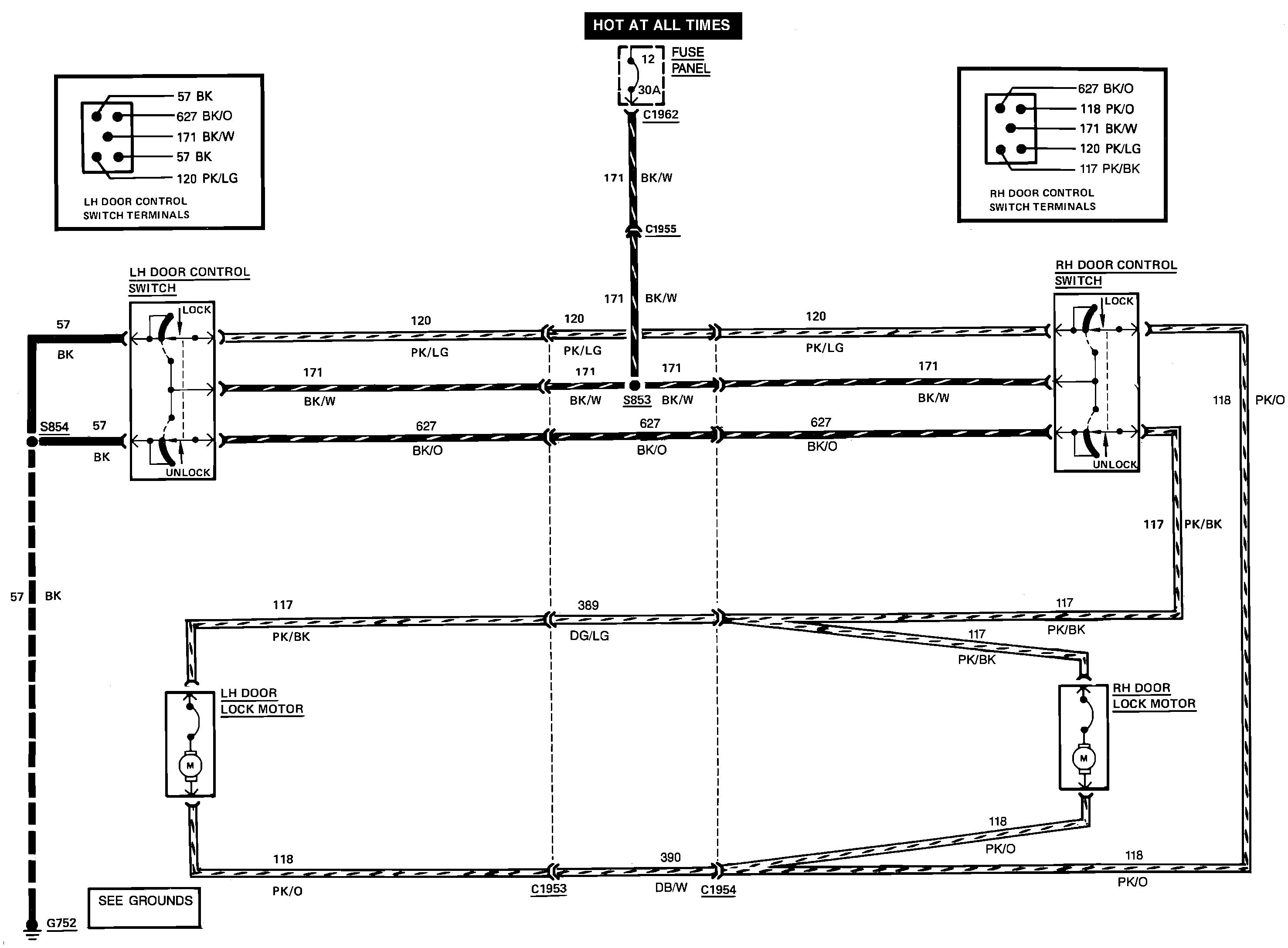
What makes power lock and power window circuits confusing is there are actually four sets of switch contacts inside each switch. When both are released, all wires and all terminals in the circuit will read continuity to ground, except the one 12-volt feed wire at each switch.
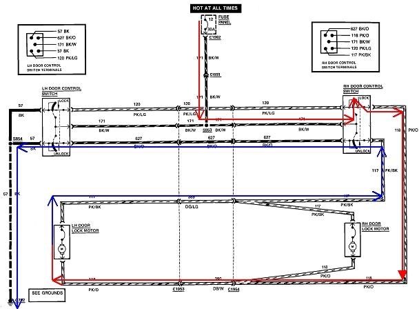
I traced the current path for locking from the passenger's switch. If you follow my nifty red arrows from the circuit breaker, down to the top of the right switch, the top part is moved away from its at-rest position, (which was grounded), to the 12-volt feed contact. Current follows the red arrows to both lock motors. All the 12 volts is dropped across the motors, so from now on we're on the ground side. There should be 0 volts the rest of the way. Those are the blue arrows. Current for both motors goes back to the second part of the passenger's switch which is released, through that, over to the driver's switch, through one of the released contacts in it, then to ground.
Manufacturers will never rely on the painted door hinge pins to make a reliable ground, so that last ground wire goes through the tube between the hinges, then is bolted to the body inside the cabin, never in the door itself. That last ground wire is a common failure when it frays and breaks, but the symptom would be the entire system is dead, both lock and unlock, from all the switches.
The circuit I traced is for locking from the passenger's switch, which I assume is working. Everything with an arrow has to be okay, but remember, there's still two more sets of contacts in each switch.
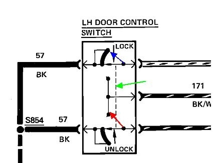
The second drawing is of an enlarged driver's switch. The dashed line, (green arrow), indicates the two switches move together when you press the lever. This is shown being pressed for "unlock". For the top part, the movable contact, (blue arrow), has simply moved from one point to another along that curved black strip. That is a ground contact, and electrically-speaking, nothing has changed there between the switch released or the switch pressed.
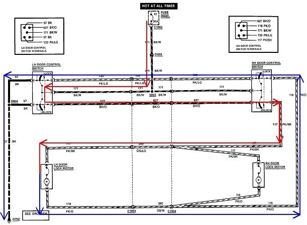
The magic happens in the bottom part of the assembly. When pressed to "unlock", that movable contact, (red arrow), first breaks the connection to its black curved ground contact, then it makes the connection to the 12-volt feed contact. The third drawing shows the circuit with the driver's switch in that "unlock" position. Current has to go through this contact, through one released contact in the other switch, through the lock motors, back through the second set of contacts in the passenger's switch, through two pairs of door hinges, then the top of the driver's switch, and then to ground. Something along this path is stopping current from flowing in your truck, but remember, we already know which parts are okay from the first drawing.
The point of this wondrous story is to show that regardless if you're locking or unlocking, and which switch is pressed, current always flows through four sets of switch contacts. In the first drawing where the top right "lock" contact is working, it is very possible it has a burned contact in the released position. When you have a power window or power lock switch that works in the pressed position, it can be defective in the released position.
If your doors lock from both switches, following the diagram shows that at some point, every wire that runs between the door hinges gets used, so that suggests none are broken. That leaves the switches as the logical suspects. You can do a series of voltage tests to figure out where the circuit is broken, but that requires pulling the switches out of the door panels. As long as you have to go through all that work, the fastest test would be to get some used switches from a salvage yard and just pop one in as a test. I don't recommend trying to solve this with an ohm meter. The meter's leads will have a few ohms of resistance themselves. A high-resistance connection or contact can have fewer ohms than the meter's leads, yet that would be more than enough to limit current flow to the point the lock actuators can't work. It's too easy to overlook a bad connection with an ohm meter in any high-current circuit.
Images (Click to enlarge)
Jan 7, 2019 at 6:15 PM