Good morning,
This code is for the canister purge valve. I attached the description and procedure for you at the bottom.
https://www.2carpros.com/articles/how-emission-control-systems-work
I see you replaced the valve. Do you have a scan tool that can see if the ECM is commanding the valve open?
As far as running rough, what have you done so far?
https://www.2carpros.com/articles/engine-misfires-or-runs-rough
Roy
This DTC tests for proper intake manifold vacuum flow to the evaporative emission (EVAP) system. The control module opens the EVAP canister purge solenoid valve and closes the EVAP canister vent solenoid valve. The control module then monitors the fuel tank pressure (FTP) sensor to determine if a vacuum is being drawn on the EVAP system. If vacuum in the EVAP system is less than a predetermined value within a predetermined time, this DTC sets. The preceding table illustrates the relationship between the ON and OFF states, and the Open or Closed states of the EVAP canister purge and vent solenoid valves.
Conditions for Running the DTC
DTCs P0030, P0031, P0032, P0053, P0100, P0101, P0102, P0103, P0106, P0107, P0108, P0112, P0113, P0114, P0117, P0118, P0119, P0122, P0123, P0128, P0130, P0131, P0132, P0133, P0135, P0221, P0222, P0223, P0443, P0449, P0450, P0451, P0452, P0453, P0458, P0459, P0498, P0499, P0501, P0502, P167A, P2122, P2123, P2127, P2128, P2138, P2177, P2178, P2187, P2188, P2195, P2196, P2199, P2227, P2228, P2229, P2237, P2243, P2251, P2297, P2626 are not set.
The ignition voltage is between 11-18 volts.
The barometric pressure (BARO) is more than 68 kPa.
The fuel level is between 15-85 percent.
The fuel tank pressure is between -2.5 and +1.3 kPa (-10 and +5 in H2O).
The engine coolant temperature (ECT) is between 4-30°C (39-86°F).
The intake air temperature is between 2-32°C (35.6-90°F).
The start-up ECT and IAT are within 9°C (14.4°F) of each other.
The vehicle speed sensor (VSS) is less than 1.7 km/h (2 mph).
DTC P0497 will attempt to run up to 10 times until it successfully completes.
DTC P0497 completes one test per cold start within 10 minutes of start-up.
Conditions for Setting the DTC
The control module detects weak vacuum during a purge condition.
The fuel tank vacuum is less than -1 inches H2O for 4 seconds continuously or 50 seconds cumulative, within 10 minutes of cold start.
The 11 second test can run up to 10 times within 10 minutes of cold start and must be completed before this DTC will set.
Action Taken When the DTC Sets
DTCs P0497 is a Type B DTC.
Conditions for Clearing the MIL/DTC
DTCs P0497 is a Type B DTC.
Reference Information
Schematic Reference
Engine Controls Schematics (See: Powertrain Management > Electrical)
Evaporative Emissions Hose Routing Diagram (See: Emission Control Systems > Vacuum and Vapor Hose > Evaporative Emissions Hose Routing Diagram)
Connector End View Reference
Component Connector End Views (See: Vehicle > Connector Views)
Electrical Information Reference
Circuit Testing (See: Vehicle > Component Tests and General Diagnostics)
Connector Repairs (See: Vehicle > Component Tests and General Diagnostics)
Testing for Intermittent Conditions and Poor Connections (See: Vehicle > Component Tests and General Diagnostics)
Wiring Repairs (See: Vehicle > Component Tests and General Diagnostics)
DTC Type Reference
Powertrain Diagnostic Trouble Code (DTC) Type Definitions (See: A L L Diagnostic Trouble Codes ( DTC ) > Diagnostic Trouble Code Descriptions)
Scan Tool Reference
Control Module References (See: Vehicle > Programming and Relearning) for scan tool information
Special Tools
J 41413-200 (J 41413-100) Evaporative Emission System Tester (EEST)
GE-41415-50 Fuel Tank Cap Adapter
Circuit/System Verification
Important: Larger volume fuel tanks and/or those with lower fuel levels may require several minutes for the floating indicator to stabilize. Refer to J J 41413-200 (J 41413-100) operation manual for detailed instructions in Evaporative Emission System Diagnosis (See: Computers and Control Systems > Component Tests and General Diagnostics > Evaporative Emission System Diagnosis) .
1. Using the GE-41415-50 , connect the J 41413-200 (J 41413-100) to the vehicle filler neck.
2. Seal the system with a scan tool and use the flow meter on the J 41413-200 (J 41413-100) calibrated to 0.51 mm (0.020 in) to determine there is no leak in the EVAP system.
If a leak is detected, use the J 41413-200 (J 41413-100) to apply smoke to the EVAP system at the filler neck until the leak is located.
Circuit/System Testing
Important: Perform the Circuit/System Verification before proceeding with the Circuit/System Testing.
1. Start the engine.
2. Seal the EVAP system using the Purge/Seal function with a scan tool.
3. Command the EVAP canister purge solenoid valve to 50 percent.
4. Observe the FTP sensor with a scan tool. The Fuel Tank Pressure Sensor parameter should be more than 2 volts after 60 seconds.
If the Fuel Tank Pressure Sensor parameter is less than the specified range, repair the blocked purge path or replace the EVAP canister purge solenoid valve.
Repair Instructions
Perform the Diagnostic Repair Verification (See: A L L Diagnostic Trouble Codes ( DTC ) > Verification Tests) after completing the diagnostic procedure.
Evaporative Emission Canister Purge Solenoid Valve Replacement (See: Canister Purge Solenoid > Removal and Replacement > Evaporative Emission Canister Purge Solenoid Valve Replacement)
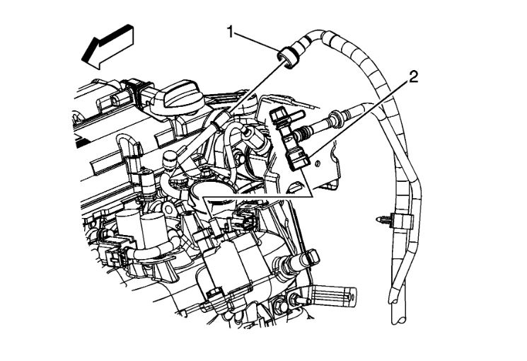
1. Disconnect the chassis evaporative emission (EVAP) line quick connect fitting (2) from the purge solenoid. Refer to Plastic Collar Quick Connect Fitting Service (See: Fuel Line Coupler > Removal and Replacement > Plastic Collar Quick Connect Fitting Service) .
imageOpen In New TabZoom/Print
2. Disconnect the engine wiring harness electrical connector (1) from the EVAP canister purge solenoid.
imageOpen In New TabZoom/Print
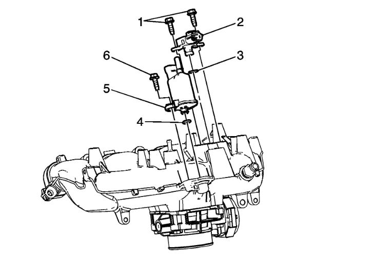
3. Remove the EVAP canister purge solenoid bolt (6).
4. Remove the EVAP canister purge solenoid (5).
5. Remove the EVAP canister purge solenoid O-ring seal (4), if necessary.
6. Inspect for carbon release in the EVAP canister purge solenoid ports. If there is any loose carbon, replace the EVAP canister and any components necessary to remove the carbon particles.
Installation Procedure
imageOpen In New TabZoom/Print
1. Install the EVAP canister purge solenoid O-ring seal (4) to the solenoid, if necessary.
2. Lubricate the O-ring seal with clean engine oil.
3. Install the EVAP canister purge solenoid to the intake manifold.
Notice: Refer to Fastener Notice (See: Vehicle > Vehicle Damage Warnings > Fastener Notice) .
4. Install the EVAP canister purge solenoid bolt.
Tighten the bolt to 10 N.m (89 lb in).
imageOpen In New TabZoom/Print
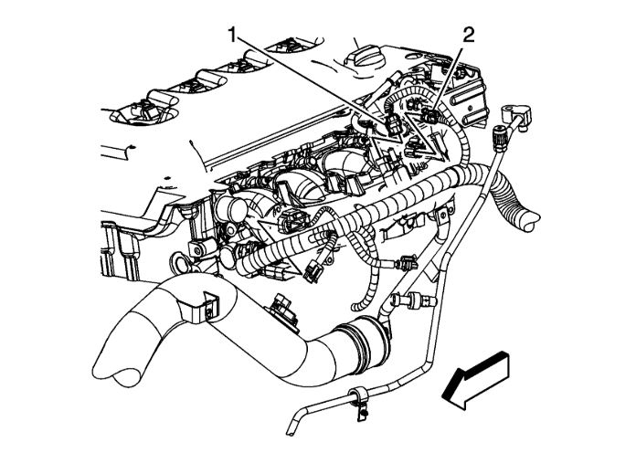
5. Connect the engine wiring harness electrical connector (1) to the EVAP canister purge solenoid.
imageOpen In New TabZoom/Print
6. Connect the chassis EVAP line quick connect fitting (2) to the purge solenoid. Refer to Plastic Collar Quick Connect Fitting Service (See: Fuel Line Coupler > Removal and Replacement > Plastic Collar Quick Connect Fitting Service) .
Images (Click to enlarge)
May 8, 2020 at 8:20 AM