Good afternoon,
I posted the description below.
Even if it is working, the passages could be clogged with carbon which is a common issue.
Roy
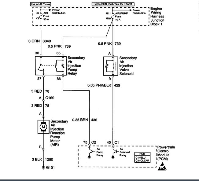
CIRCUIT DESCRIPTION
An AIR pump is used on this vehicle to lower tail pipe emissions on start-up. The PCM grounds the AIR pump relay control circuit, which energizes the AIR pump. The PCM also grounds the AIR solenoid valve, which allows vacuum to AIR solenoid valves. The PCM enables both control circuits when AIR system operation is desired. When the AIR system is active, the AIR pump forces fresh air into the exhaust stream in order to accelerate catalyst operation. When the AIR system is inactive, the AIR solenoid valves prevent air flow in either direction. DTC P0412 applies to the AIR solenoid control circuit. DTC P0418 applies to the AIR pump relay control circuit. DTC P0410 sets if an air flow problem is detected.
DTC P0410 consists of Passive and Active Tests. The Passive test is executed after the engine is started, and consists of two parts (Passive Test 1 and Passive Test 2).
The passive test consists of the following:
Passive Test 1
When the AIR system is enabled, the PCM monitors the HO2S voltage. If the HO2S voltage goes below a threshold, the PCM interprets this as an indication that the AIR system is operational.
Passive Test 2
When the AIR system is disabled, the PCM monitors the HO2S voltage. The HO2S voltage should increase above a threshold and switch normally. If both of these tests indicate a pass, no further action is taken. If one of the above tests failed or is inconclusive, the diagnostic will proceed to the Active Test.
The Active Test is performed specifically for diagnostic purposes, and consists of the following:
Active Test
During this test the PCM turns the AIR system on during closed loop operation. When the AIR system is activated, the PCM monitors the HO2S 1 voltage and ST Fuel Trim. If the AIR system is operating properly, the HO2S 1 voltage should go below a predetermined threshold. The Active Test may run up to 4 times before failing.
CONDITIONS FOR AIR SYSTEM OPERATION
PCM must have accumulated at least 10 Miles.
ECT between 4.5°C (40.1°F) and 30°C (86°F)
IAT greater than 4.5°C (40.1°F)
IAT Less than 70°C (158°F)
BARO greater than 75 kPa
MAF less than 40 gm/s
CONDITIONS FOR RUNNING THE DTC
DTCs P0101, P0102, P0103, P0107, P0108, P0112, P0113, P0117, P0118, P0121, P0122, P0123, P0171, P0172, P0300, P0412, P0418, P0442, P0443, P1441 and HO2S DTCs not set.
Passive Test
Engine is running
TP sensor steady
Engine load is less than 80 percent
Engine air flow is less than 35 g/s
Ignition voltage is greater than 11.0 volts
Air fuel ratio is greater than 11.5:1
Start up ECT is less than 30°C (86°F)
IAT is greater than 4.5°C (40.1°F)
The AIR system is enabled for up to 70 seconds
Passive Test fails if:
HO2S1 voltage does not fall below a voltage threshold for a calibrated amount of time. (Passive Test 1)
HO2S1 voltage does not rise above a voltage threshold for a calibrated amount of time after the pump is turned off. (Passive Test 2)
Active Test
The engine operates for greater than 5 minutes.
Manifold vacuum is greater than 45 kPa.
Vehicle is not in Park/Neutral.
Engine speed is greater than 900 RPM.
Air flow is less than 15 g/s.
ECT is greater than 75°C (167°F).
Accumulate 40 seconds of time in Fuel Trim Cell 2 (steady state cruise) with EVAP Purge active.
Ignition voltage is greater than 11.0 volts.
Fuel system operating in Closed Loop.
Active Test fails if the HO2S 1 voltage does not fall below a voltage threshold for a calibrated amount of time.
CONDITIONS FOR SETTING THE DTC
If a total of 4 Active and/or Passive Test failures, P0410 is set.
ACTION TAKEN WHEN THE DTC SETS
The PCM will illuminate the Malfunction Indicator Lamp (MIL) during the second consecutive trip in which the diagnostic test has been run and failed.
The PCM will store conditions which were present when the DTC set as Freeze Frame and Failure Records data.
CONDITIONS FOR CLEARING THE MIL/DTC
The PCM will turn OFF the MIL during the third consecutive trip in which the diagnostic has been run and passed.
The History DTC will clear after 40 consecutive warm-up cycles have occurred without a malfunction.
The DTC can be cleared by using a scan tool.
DIAGNOSTIC AIDS
The following may cause an intermittent:
IMPORTANT: Remove any debris from the connector surfaces before servicing a component. Inspect the connector gaskets when diagnosing or replacing a component. Ensure that the gaskets are installed correctly.
The gaskets prevent contaminate intrusion.
Poor terminal connection.
Inspect the harness connectors for backed out terminals, improper mating, broken locks, improperly formed or damaged terminals, and faulty terminal to wire connection. Use a corresponding mating terminal to test for proper tension. Refer to Testing for Intermittent and Poor Connections and Connector Repairs in Diagrams.
Damaged harness.
Inspect the wiring harness for damage. If the harness appears to be OK, observe the display on the scan tool while moving connectors and wiring harnesses related to the sensor. A change in the display may indicate the location of the fault. Refer to Circuit Testing and Wiring Repairs in Diagrams.
Inspect the PCM and the engine grounds for clean and secure connections.
If the DTC is determined to be intermittent, reviewing the Failure Records can be useful in determining when the DTC was last set.
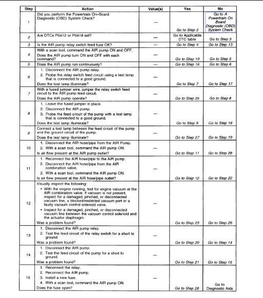
TEST DESCRIPTION
The numbers below refer to the step numbers on the diagnostic table.
2. DTC P0412 AIR Solenoid Valve Control Circuit and P0418 AIR Pump Relay Control Circuit should be diagnosed first if either are set.
3. Begins testing for a short to ground in the AIR pump feed circuit.
4. Listen for a running motor. Command both the ON and OFF states. Repeat the commands as necessary.
5. Begins testing for a short to voltage in the pump feed circuit.
6. Tests for voltage at the AIR pump relay switch feed circuit.
7. Bypasses the relay.
8. Tests for voltage on the AIR pump feed circuit.
9. Tests for an open on the pump ground circuit.
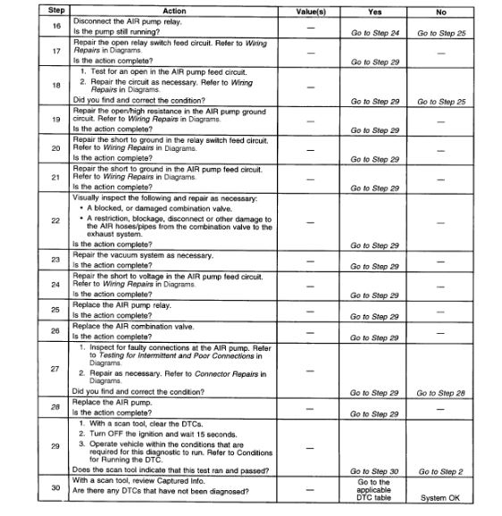
28. The AIR Pump is not designed to run continuously. If the pump needs to be replaced, inspect for conditions that may cause continuous pump operation.
Images (Click to enlarge)
Oct 21, 2019 at 12:41 PM