Code P0533, can I get the pinout diagram for ECM?

Tiny
NOWAYJOSE33
  • MEMBER
  • 2017 DODGE GRAND CARAVAN
  • 3.6L
  • 6 CYL
  • 2WD
  • AUTOMATIC
  • 120,000 MILES
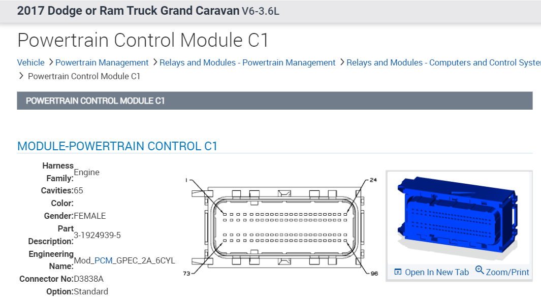
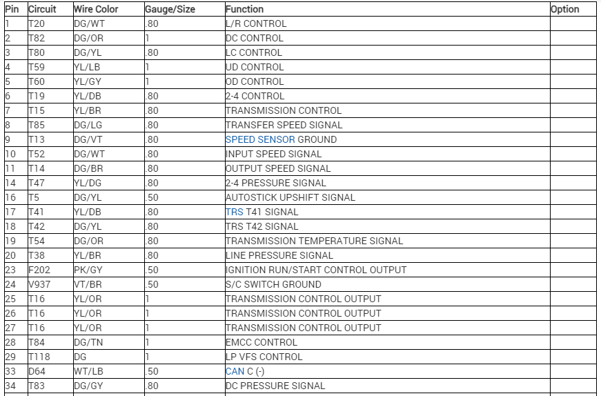
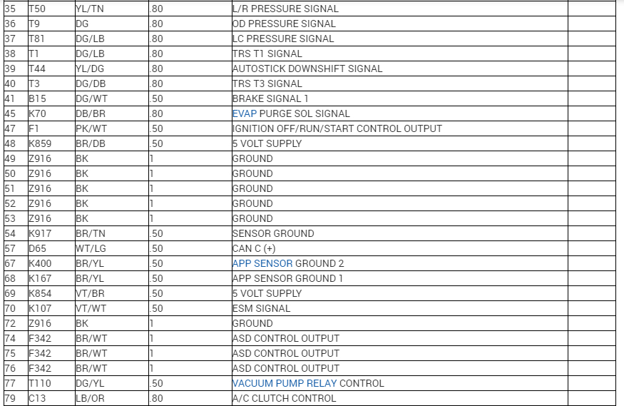
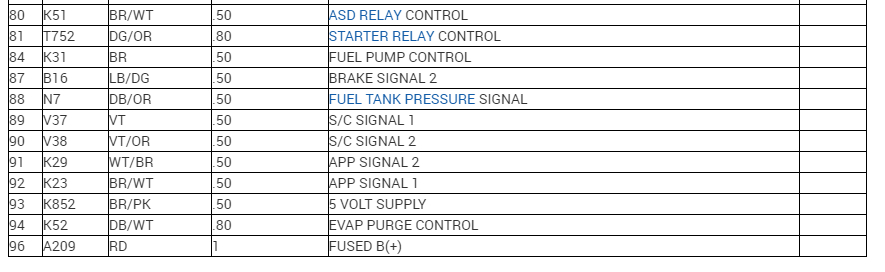
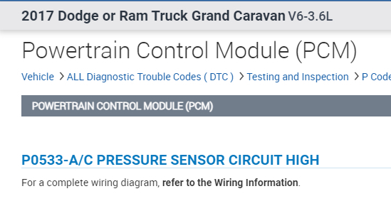
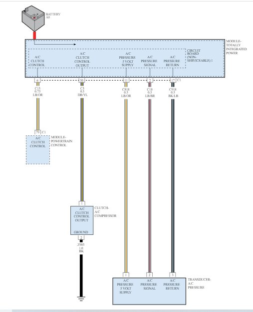
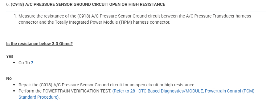
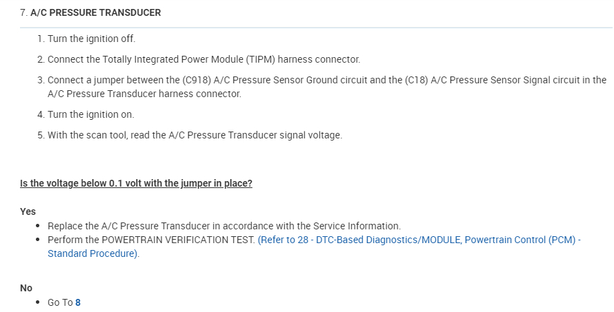
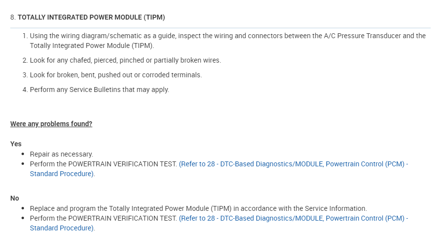
Need pinout diagram for ECM of the van listed above SXT model, flex fuel with front/rear A/C. Have new A/C compressor, both evaporators, receiver/dryer, both sensors, and ECM. All fuses and relays are good. Still get code #P0533 A/C Sending Unit Volts Too High.
Sunday, September 3rd, 2023 AT 12:27 PM

6 Replies

Tiny
JACOBANDNICKOLAS
  • MECHANIC
  • 108,269 POSTS
Hi,

The first seven pics below are the pin-out information I have. For some reason, connector 2 provides a legend but not the connector.

However, I don't think this is a PCM issue. It could be a short or an issue with the totally integrated power module (TIPM).

Take a look at the remaining pics. They provide a description of the code as well as diagnostics.

Let me know if this helps.

Take care,

joe

See pics below.
Was this
answer
helpful?
Yes
No
Sunday, September 3rd, 2023 AT 10:55 PM
Tiny
NOWAYJOSE33
  • MEMBER
  • 4 POSTS
Disconnected the a/c pressure sending unit harness connector. Checked connectors. Measured voltage between the (K72E) supply circuit and (K55) return circuit of the sensor harness connector. Voltage was 5. While monitoring, used jumper wire to connect the return circuit (K55) to the signal circuit (C18). PO532 did not set. Turned ignition off and disconnected ECM harness connectors. Checked. Measured voltage between (K72E) supply circuit at the harness connector and battery negative. Voltage was.33 millivolts. Attempted to measure resistance of the (K55) return circuit between the sensor harness connector and the ECM harness connector but was unable to locate pin since this was before you sent the diagrams. Thank you for the pinout diagrams.
Was this
answer
helpful?
Yes
No
Tuesday, September 5th, 2023 AT 6:05 AM
Tiny
JACOBANDNICKOLAS
  • MECHANIC
  • 108,269 POSTS
Hi,

No problem whatsoever. Were you able to find the issue?

Joe
Was this
answer
helpful?
Yes
No
Tuesday, September 5th, 2023 AT 6:00 PM
Tiny
NOWAYJOSE33
  • MEMBER
  • 4 POSTS
No chance to check it out yet. Car is in use. Do you know why there is no check engine light even with what could be a major issue like this?
Was this
answer
helpful?
Yes
No
Wednesday, September 6th, 2023 AT 4:26 AM
Tiny
NOWAYJOSE33
  • MEMBER
  • 4 POSTS
As I study the diagrams you sent me, I notice that the C13 circuit shows as pin #79 on the C1 chart, but I cannot locate circuit CR18 (11), C18(2), or C918(17) as shown on the PCM to transducer diagram. Any advice on this?
Was this
answer
helpful?
Yes
No
Wednesday, September 6th, 2023 AT 7:00 AM
Tiny
JACOBANDNICKOLAS
  • MECHANIC
  • 108,269 POSTS
Hi,

The connectors you refer to are between the totally integrated power module (TIPM) and the transducer. It doesn't show the PCM.

The printed circuit board in the TIPM is something that is not serviceable. If it is bad, the TIPM will need to be replaced.

Let me know.

Take care,

Joe
Was this
answer
helpful?
Yes
No
Wednesday, September 6th, 2023 AT 5:38 PM

Please login or register to post a reply.

Sponsored links