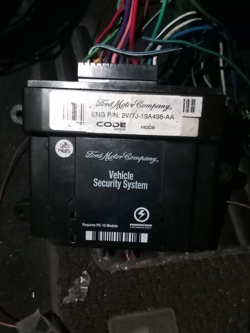
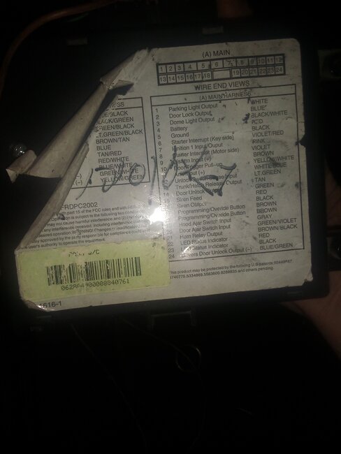
The box on the left is the disconnected theft unit. The various wires that come from it are color coded and numbered at the connector as to where they go. Then you see the black dots? Those are connection splices. Dotted lines or outlines are for incomplete items. Say you have fuse 5 which comes out of the fuse box at terminal 10 and feeds the alarm at pin 3 in the B connector. The dotted lines at the top mean the fuse powers other items as well.
These might help you understand a bit better:
https://www.youtube.com/watch?v=mEJEHxlbn9o
https://www.youtube.com/watch?v=icOIfBwWIPc
https://www.youtube.com/watch?v=0r0ELnmZ0-k
https://www.youtube.com/watch?v=h3FsEV49CvM P1
https://www.youtube.com/watch?v=UTgc44iqd1c P2
https://www.youtube.com/watch?v=yV4ca2e4spo
If you look at the diagram you can see that from the factory this unit is connected into a lot of systems, adding it on after the fact is a mess as you have discovered now. Normally I would suggest just going into the wiring and finding any cut or spliced wires and removing the add-on item completely. For that though you would need wiring diagrams for each system as well as the original diagram without that added part. For that I would suggest getting service information yourself. You can get a limited version of what we use from Alldata or Mitchell. That way you can have all the information at your fingertips as well.
Alldata -
https://www.alldata.com/diy-us/en
Mitchell -
https://eautorepair.net/
Both offer the wiring and connector views as well as a tutorial on using them.
Both also have print options so you could print sections to .pdf files for later use... like after the subscription expired...
Apr 14, 2025 at 10:28 AM