Hi and thanks for using 2CarPros.
The code is related to the High Voltage Traction Battery. The high-voltage traction battery (HVTB) is a 300 volt DC power source. If the light is on, delete the code and see if it returns. If it does, replace the HVTB.
Here are specific directions for replacement:
First, you need to depower the unit: See pictures 1 and 2
HIGH-VOLTAGE TRACTION BATTERY SYSTEMS DEPOWERING
High-Voltage Traction Battery Systems Depowering
WARNING: When servicing the high-voltage system, establish a buffer zone per the specified procedure. Failure to follow this instruction may result in serious personal injury or death.
WARNING: Depower the high-voltage traction battery (HVTB) before carrying out any removal or installation procedures affecting the high-voltage battery system. Failure to follow this instruction may result in serious personal injury or death.
WARNING: Wear high-voltage insulated safety gloves and a face shield when working with high-voltage batteries or cables. The high-voltage insulated safety gloves should be of the appropriate safety and protection rating. Inspect the gloves before use and always wear them with the leather outer glove. Any hole in the rubber insulating glove is a potential entry point for high-voltage. Failure to follow these instructions may result in serious personal injury or death.
WARNING: Turn OFF the ignition switch for a minimum of 5 minutes before removing high-voltage cables. High-voltage cables and wiring are orange in color. The nominal high-voltage traction battery voltage (HVTB) is 330 V DC. Failure to follow these instructions may result in serious personal injury or death.
1. Set up the buffer zone around the vehicle. For additional information, refer to Buffer Zone. See: Battery System, Hybrid Drive > Procedures > Buffer Zone
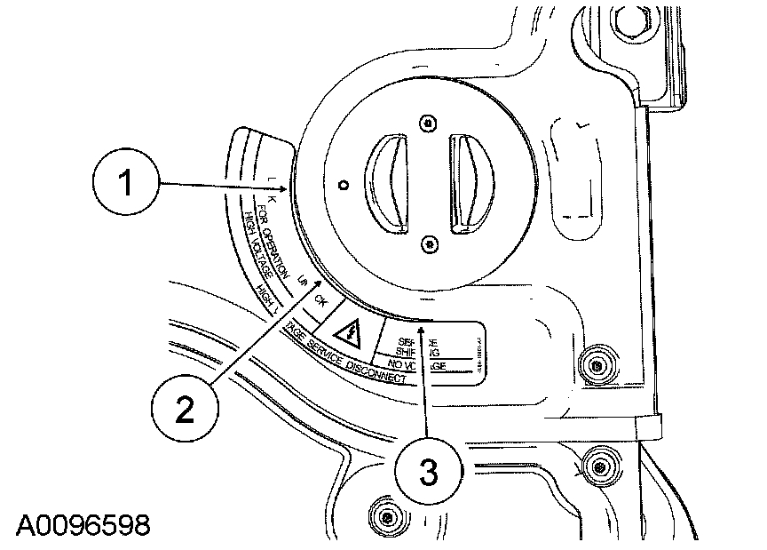
2. Remove the service disconnect plug in the following sequence.
1. Rotate the service disconnect plug from the lock (1) position to the unlock (2) position.
2. Remove the service disconnect plug and place in the servicing shipping (3) position.
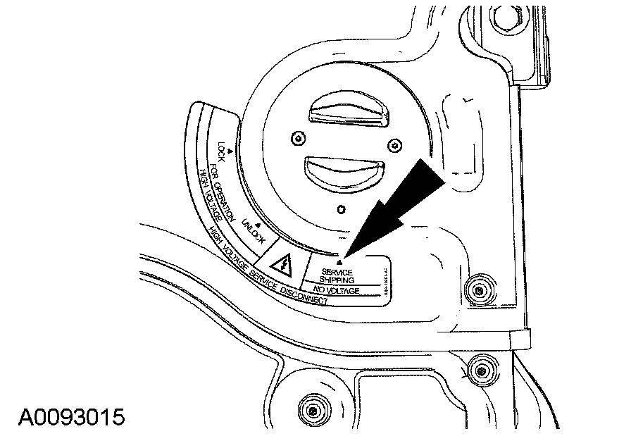
3. NOTICE: Place the service disconnect plug into the servicing shipping position while the High Voltage Traction Battery (HVTB) is being removed and/or while the high-voltage system is having repairs carried out. If the service disconnect plug is left out and placed on the bench or toolbox, dirt or other contaminants may enter the HVTB, which can cause damage.
Insert the service disconnect plug into the servicing shipping position. This disconnects the High Voltage Traction Battery (HVTB).
4. To connect, reverse the disconnect procedure.
_______________________________-_______
Here are the directions for replacement. Pics 3 - 7
HIGH-VOLTAGE TRACTION BATTERY
HIGH-VOLTAGE TRACTION BATTERY
Removal and Installation
WARNING:
- When servicing the high-voltage system, establish a buffer zone per the specified procedure. Failure to follow this instruction may result in serious personal injury or death.
- Depower the high-voltage traction battery (HVTB) before carrying out any removal or installation procedures affecting the high-voltage battery system. Failure to follow this instruction may result in serious personal injury or death.
- Wear high-voltage insulated safety gloves and a face shield when working with high-voltage batteries or cables. The high-voltage insulated safety gloves should be of the appropriate safety and protection rating. Inspect the gloves before use and always wear them with the leather outer glove. Any hole in the rubber insulating glove is a potential entry point for high-voltage. Failure to follow these instructions may result in serious personal injury or death.
- Turn OFF the ignition switch for a minimum of 5 minutes before removing high-voltage cables. High-voltage cables and wiring are orange in color. The nominal high-voltage traction battery voltage (HVTB) is 330 V DC. Failure to follow these instructions may result in serious personal injury or death.
NOTE: A replacement high-voltage traction battery (HVTB) may have a low state of charge that is insufficient to start the vehicle. If this occurs, follow the instructions for the jump start procedure in the Owner's Literature.
1. Depower the HVTB.
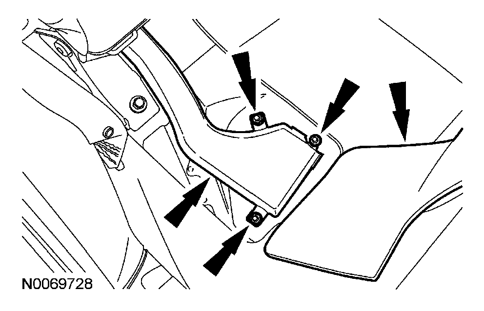
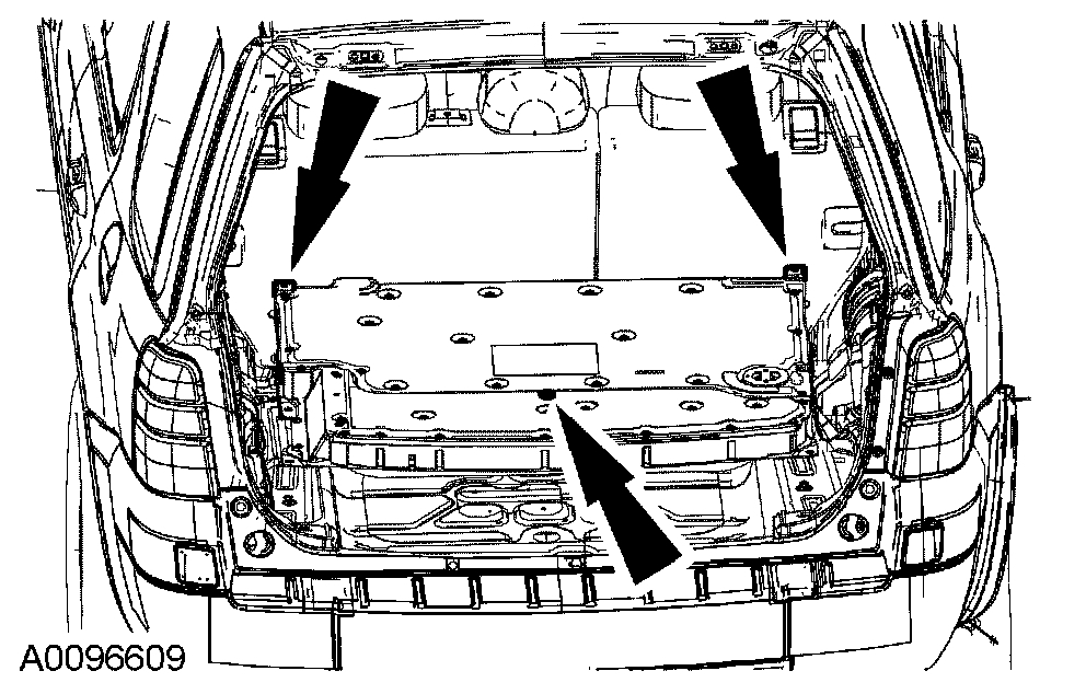
2. Remove the rear cargo area carpet insert.
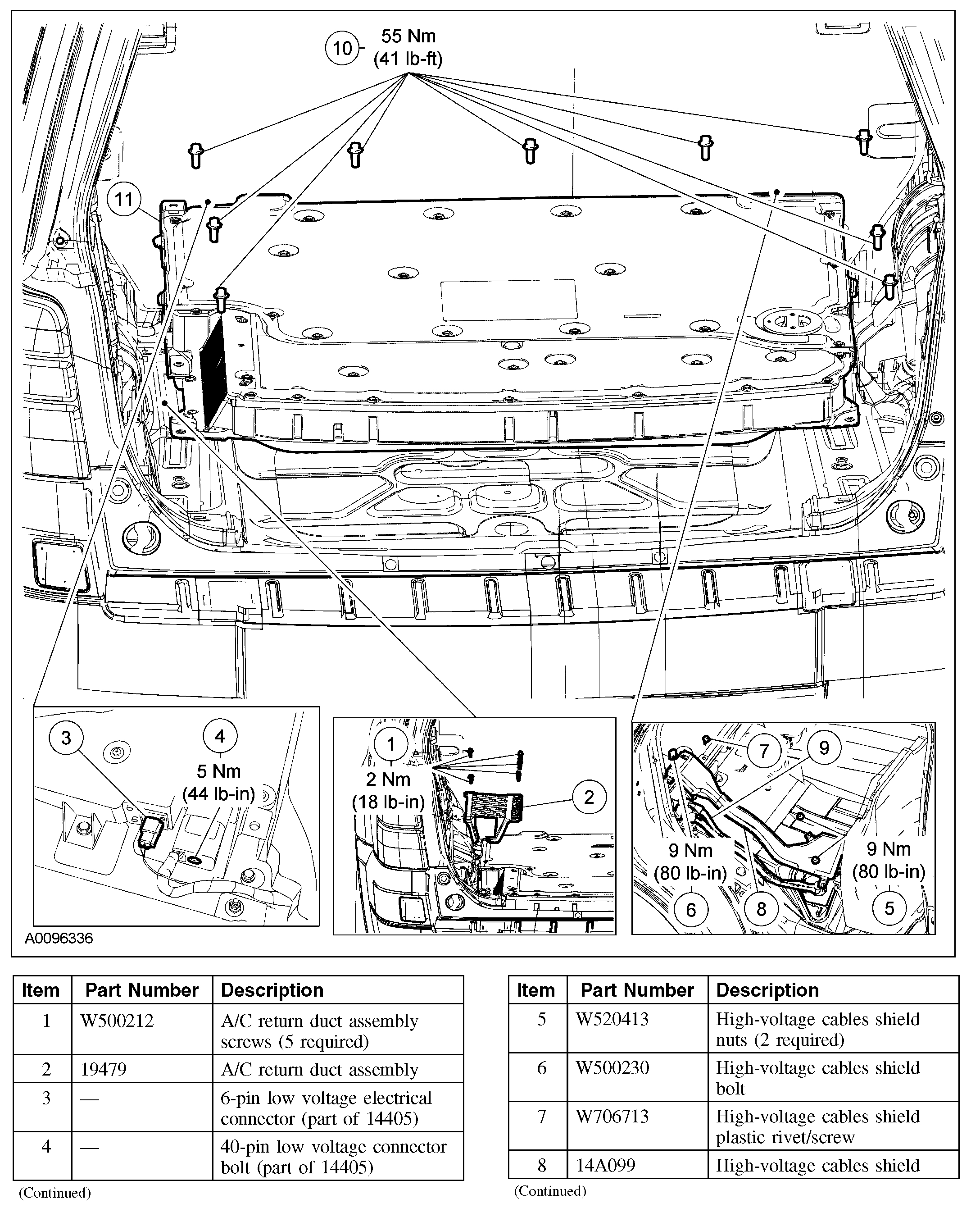
3. NOTE: When installing, tighten the screws on the HVTB first or an airflow loss to the HVTB may occur.
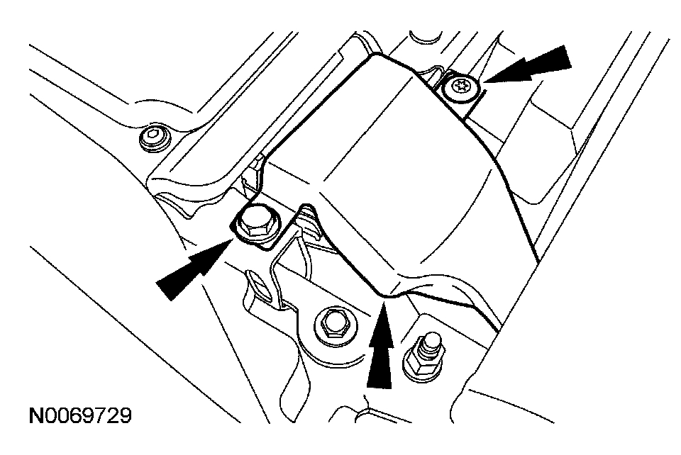
Remove the 5 A/C return duct assembly screws.
- To install, tighten to 2 Nm (18 lb-in).
4. Remove the A/C return duct assembly.
5. NOTE: Due to clearance issues, the 6-pin connector must be disconnected first during the removal process and connected last during the installation process.
From the left rear door opening, fold the left rear seat backrest down and disconnect the 6-pin low voltage electrical connector.
6. NOTE: Due to clearance issues, the 40-pin connector must be disconnected last during the removal process and connected first during the installation process.
Loosen the bolt and disconnect the 40-pin low voltage connector.
- To install, tighten to 5 Nm (44 lb-in).
7. From the right rear door opening, fold the right rear seat cushion forward and remove the 2 high-voltage cables shield nuts (access the shield nuts through the slotted opening in the carpet).
- To install, tighten to 9 Nm (80 lb-in).
8. Fold the right rear seat backrest down and remove the high-voltage cables shield bolt, then remove the scrivet.
- To install, tighten to 9 Nm (80 lb-in).
9. Remove the high-voltage cables shield.
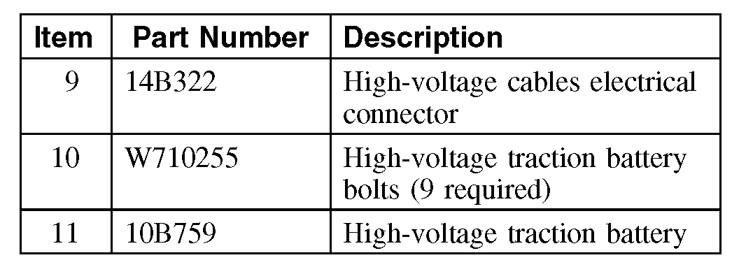
10. Press the locking tab down and rotate the locking lever upward until the aligning dowels are disengaged from the locking lever to remove the high-voltage cables electrical connector.
11. NOTE: The attaching bolts have a conductive coating on them and are serrated under the head flange. These features ground the HVTB to the vehicle, which is required for electro-magnetic compatibility (EMC). If a bolt(s) is lost or damaged, a new bolt(s) must be installed with the identical type of bolt.
Remove the 9 HVTB bolts.
- NOTE: Hand-start all of the bolts before tightening them to specification.
To install, tighten to 55 Nm (41 lb-ft).
12. NOTE:
- The 2 front lift points are the eyelets on each front corner and the rear lift point is beneath the cap plug in the center rear of the HVTB.
- Remove the cap plug to expose the center (rear) lifting attachment point. Make certain to reinstall this plug during the HVTB installation procedure to avoid noise, vibration, and harshness (NVH) issues.
- Attach 3 M10 x 1.5 x 35 eyebolts to the 3 HVTB lift points. Obtain the eyebolts locally.
- Make certain the HVTB does not mar or damage the interior panels during removal. There is only 6 mm (0.23 in) clearance on each side. Cover the battery mounting brackets with protective padding.
- Do not strike the headliner with the HVTB (or floor crane) during removal.
- Inspect the HVTB tray drain grommet located in the floor pan underneath the HVTB. Replace it if necessary.
- Failure to install the rear lift eye cap plug may result in noise, vibration and harshness (NVH) issues.
With an assistant, attach a chain or suitable lifting device to the 3 lift points and lift the HVTB off the 2 alignment dowels using a floor crane. Remove the HVTB from the vehicle.
13. To install, reverse the removal procedure.
_______________________________________
Here is what is meant by Buffer Zone: See Pic 8
BUFFER ZONE
WARNING:
- When servicing the high-voltage system, establish a buffer zone per the specified procedure. Failure to follow this instruction may result in serious personal injury or death.
- Depower the high-voltage traction battery (HVTB) before carrying out any removal or installation procedures affecting the high-voltage battery system. Failure to follow this instruction may result in serious personal injury or death.
- Wear high-voltage insulated safety gloves and a face shield when working with high-voltage batteries or cables. The high-voltage insulated safety gloves should be of the appropriate safety and protection rating. Inspect the gloves before use and always wear them with the leather outer glove. Any hole in the rubber insulating glove is a potential entry point for high-voltage. Failure to follow these instructions may result in serious personal injury or death.
- Turn OFF the ignition switch for a minimum of 5 minutes before removing high-voltage cables. High-voltage cables and wiring are orange in color. The nominal high-voltage traction battery voltage (HVTB) is 330 V DC. Failure to follow these instructions may result in serious personal injury or death.
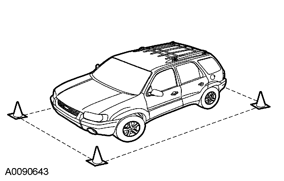
1. Position the vehicle in the repair bay.
2. Position 4 orange cones around the corners of the vehicle to mark off a 1 m (3 ft) perimeter around the vehicle.
3. Do not allow any unauthorized personnel into the buffer zone during repairs involving the high-voltage system. Only personnel trained for repair on the high-voltage system are to be permitted in the buffer zone.
_____________________________________
This is how to remedy the issue. However, it is a dangerous job. Make sure to fully follow the directions. The last picture is the code information.
Let me know if this helps or if you have other questions.
Take care,
Joe
Images (Click to make bigger)
Wednesday, January 9th, 2019 AT 8:41 PM