Good afternoon,
I attached a flow chart with a wiring diagram for you to check.
https://www.2carpros.com/articles/how-to-check-wiring
IN most cases, this could be the module but needs to be confirmed with the flow chart.
Roy
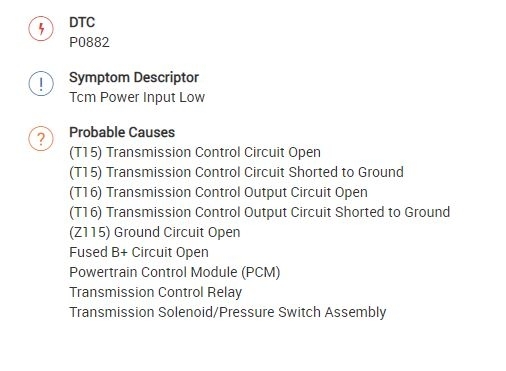
P0882-TCM POWER INPUT LOW
imageOpen In New TabZoom/Print
For a complete wiring diagram Refer to Diagrams/Electrical. See: Vehicle > Electrical
Theory of Operation
The Transmission Control Output circuit is used to supply power to the Transmission Solenoid/TRS Assembly and to the PCM when in normal operating mode. The purpose of the Transmission Output circuit is to allow the Transmission Control System to turn off the power to the Transmission Solenoid/TRS Assembly in event that the transmission should need to be placed into "limp-in" mode due to a DTC.
After a PCM reset, (ignition switch turned to the run position, or after cranking the engine) the Transmission Control System verifies that the Transmission Output circuit is open by checking for voltage on the Transmission Output circuits before the Transmission Control Relay is energized. If the Transmission Control System detects less that 3.0 volts when the output is commanded on, the DTC will set.
Note: Inadequate Transmission Control Output voltage can also cause DTCs P0846, or P0871, to set. This does not indicate an internal transmission or solenoid/TRS problem. Repairing the P0882 fault should also eliminate the related DTCs.
- When Monitored:
When the ignition is turned from "OFF" position to "RUN" position and/or the ignition is turned from "START" position to "RUN" position.
- Set Condition:
This DTC is set when there is less than 3.0 volts present at the transmission control output circuits located in the Powertrain Control Module (PCM) when the Transmission Control System request the power up of those circuits.
Note: Due to the integration of the Transmission Control Module and the Powertrain Control Module, both systems have their own power and ground circuits.
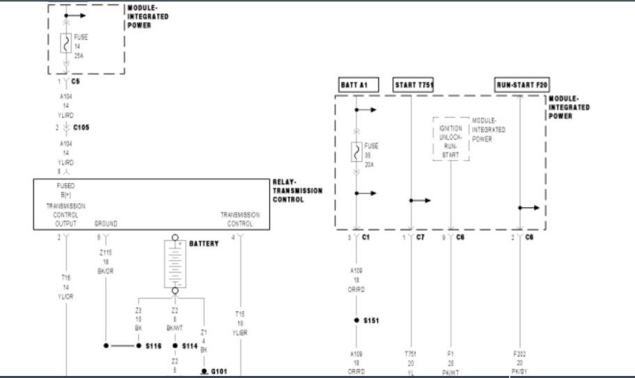
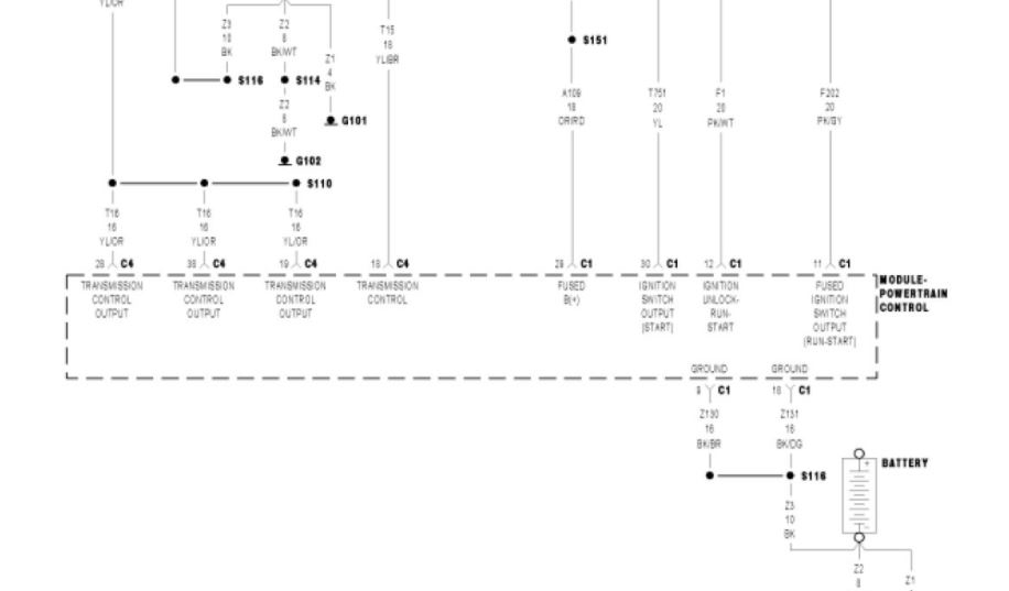
imageOpen In New TabZoom/Print
Always perform the 62TE Pre-Diagnostic Troubleshooting procedure before proceeding. See: Automatic Transmission/Transaxle > Initial Inspection and Diagnostic Overview > 62TE - Pre-Diagnostic Troubleshooting Procedure
Diagnostic Test
1. CHECK IF THE DTC P0882 IS CURRENT
With the scan tool, Check the STARTS SINCE SET counter for P0882.
NOTE: This counter only applies to the last DTC set.
Is the STARTS SINCE SET counter equal to 0?
Yes
- Go To 2
No
- Go To 5
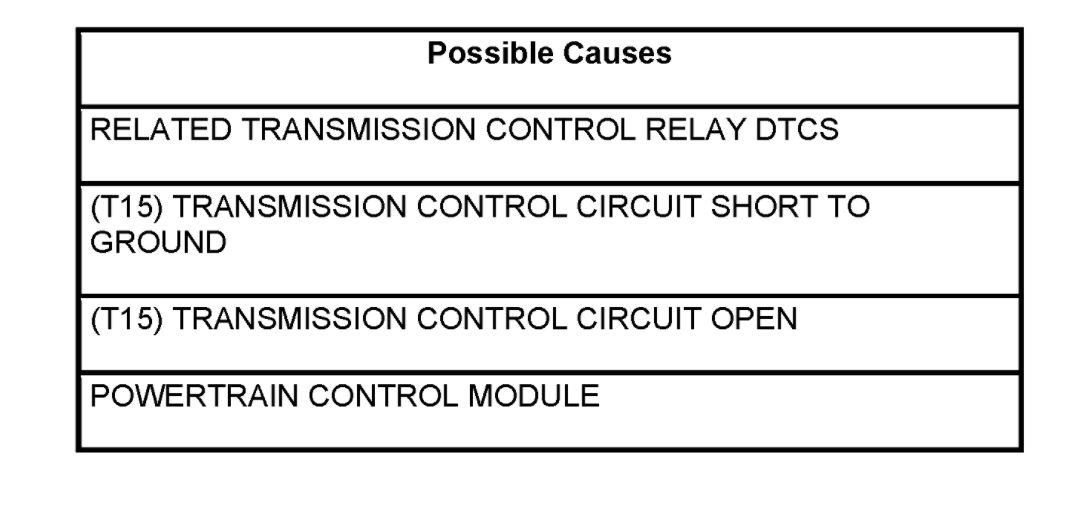
2. CHECK FOR TRANSMISSION CONTROL RELAY DTCS
With the scan tool, check TIPM DTCs.
Are there any Transmission Control Relay DTCs present?
Yes
- Refer to Transmission and Drivetrain and perform the appropriate test(s).
No
- Go To 3
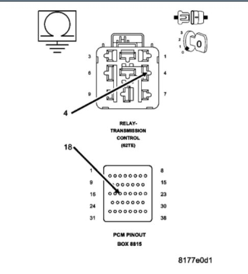
3. CHECK THE (T15) TRANSMISSION CONTROL CIRCUIT FOR A SHORT TO GROUND
imageOpen In New TabZoom/Print
Turn the ignition off to the lock position.
Disconnect the PCM C4 harness connector and connect Miller tool #8815.
CAUTION: Do not probe the PCM harness connectors. Probing the PCM harness connectors will damage the PCM terminals resulting in poor terminal to pin connection. Install Miller tool #8815 to perform diagnosis.
Remove the Transmission Control Relay.
Measure the resistance between ground and the (T15) Transmission Control circuit.
Is the resistance below 5.0 ohms?
Yes
- Repair the (T15) Transmission Control circuit for a short to ground.
- Perform 62TE VERIFICATION TEST. See: A L L Diagnostic Trouble Codes ( DTC ) > Verification Tests > 62TE Transmission Verification Test
No
- Go To 4
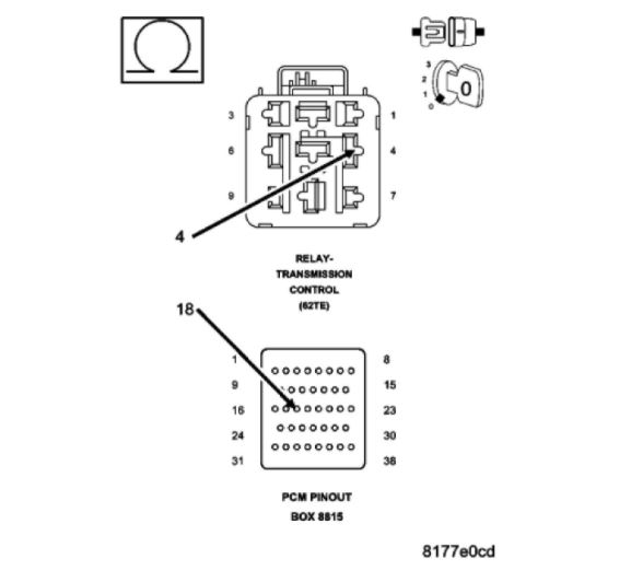
4. CHECK THE (T15) TRANSMISSION CONTROL CIRCUIT FOR AN OPEN
imageOpen In New TabZoom/Print
Measure the resistance of the (T15) Transmission Control circuit between the Transmission Control Relay connector and the appropriate terminal of Miller tool #8815.
Is the resistance above 5.0 ohms?
Yes
- Repair the (T15) Transmission Control circuit for an open.
- Perform 62TE VERIFICATION TEST. See: A L L Diagnostic Trouble Codes ( DTC ) > Verification Tests > 62TE Transmission Verification Test
No
- Using the schematics as a guide, check the Powertrain Control Module (PCM) terminals for corrosion, damage, or terminal push out. Pay particular attention to all power and ground circuits. If no problems are found, replace and program the PCM. With the scan tool, perform QUICK LEARN.
- Perform 62TE VERIFICATION TEST. See: A L L Diagnostic Trouble Codes ( DTC ) > Verification Tests > 62TE Transmission Verification Test
5. CHECK THE WIRING AND CONNECTORS
The conditions necessary to set this DTC are not present at this time.
Using the schematics as a guide, inspect the wiring and connectors specific to this circuit.
Wiggle the wires while checking for shorted and open circuits.
With the scan tool, check the DTC EVENT DATA to help identify the conditions in which the DTC was set.
Where there any problems found?
Yes
- Repair as necessary.
- Perform 62TE VERIFICATION TEST. See: A L L Diagnostic Trouble Codes ( DTC ) > Verification Tests > 62TE Transmission Verification Test
No
- Test Complete.
Images (Click to enlarge)
Feb 14, 2021 at 10:22 AM