Good morning,
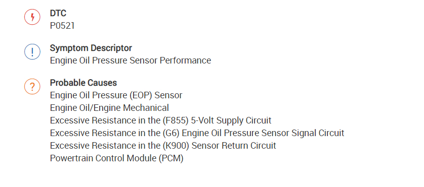
The code is for the oil pressure sensor circuit.
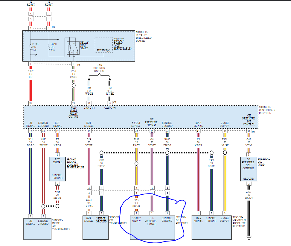
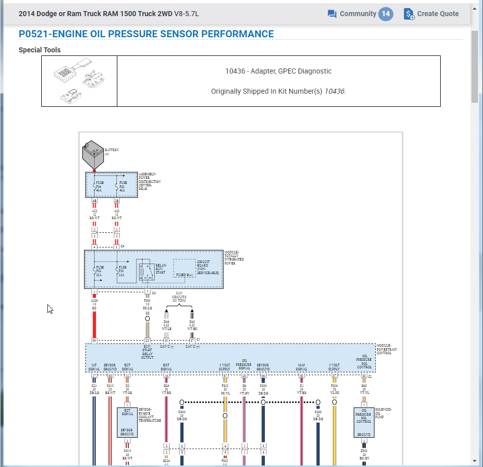
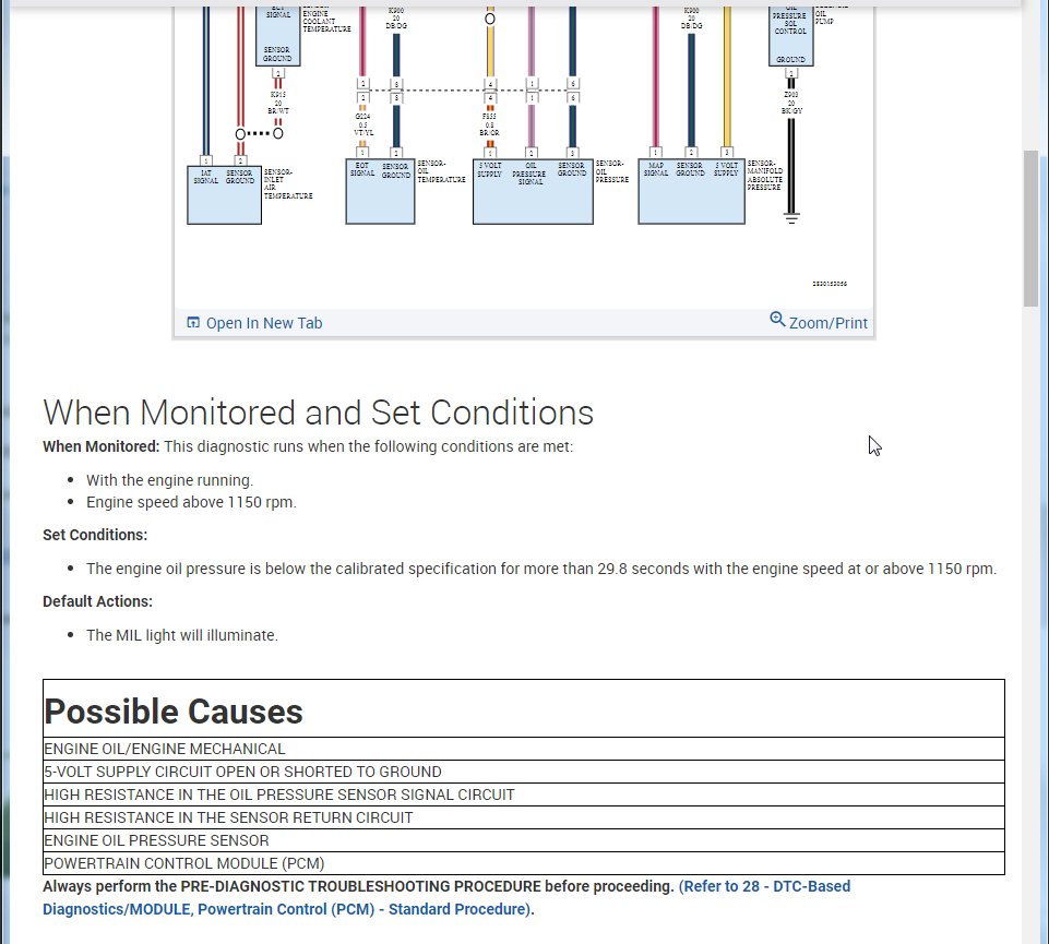
I attached a wiring diagram for you to view. You will need a voltmeter to do some checks at the connector.
https://www.2carpros.com/articles/how-to-check-wiring
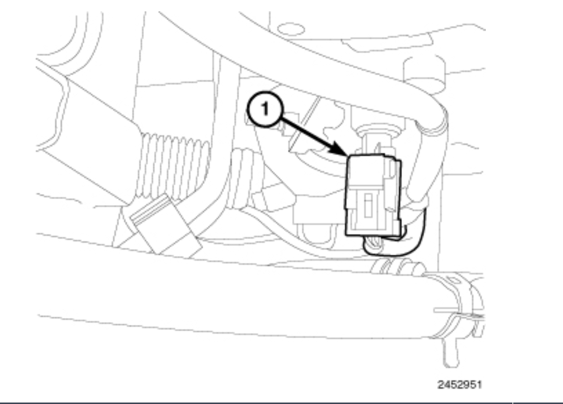
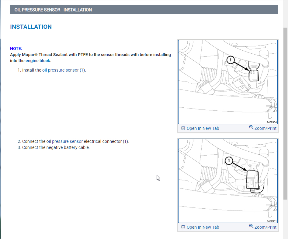
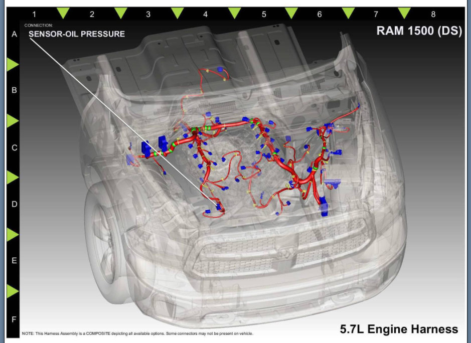
I attached a picture of the location as well.
Below is a video from YouTube for the location of the sensor.
https://www.youtube.com/watch?v=0FJ_nqJnMeY
Roy
When Monitored and Set Conditions
When Monitored: This diagnostic runs when the following conditions are met:
With the engine running.
Engine speed above 1150 rpm.
Set Conditions:
The engine oil pressure is below the calibrated specification for more than 29.8 seconds with the engine speed at or above 1150 rpm.
Default Actions:
The MIL light will illuminate.
Possible Causes
ENGINE OIL/ENGINE MECHANICAL
5-VOLT SUPPLY CIRCUIT OPEN OR SHORTED TO GROUND
HIGH RESISTANCE IN THE OIL PRESSURE SENSOR SIGNAL CIRCUIT
HIGH RESISTANCE IN THE SENSOR RETURN CIRCUIT
ENGINE OIL PRESSURE SENSOR
POWERTRAIN CONTROL MODULE (PCM)
Always perform the PRE-DIAGNOSTIC TROUBLESHOOTING PROCEDURE before proceeding. (Refer to 28 - DTC-Based Diagnostics/MODULE, Powertrain Control (PCM) - Standard Procedure).
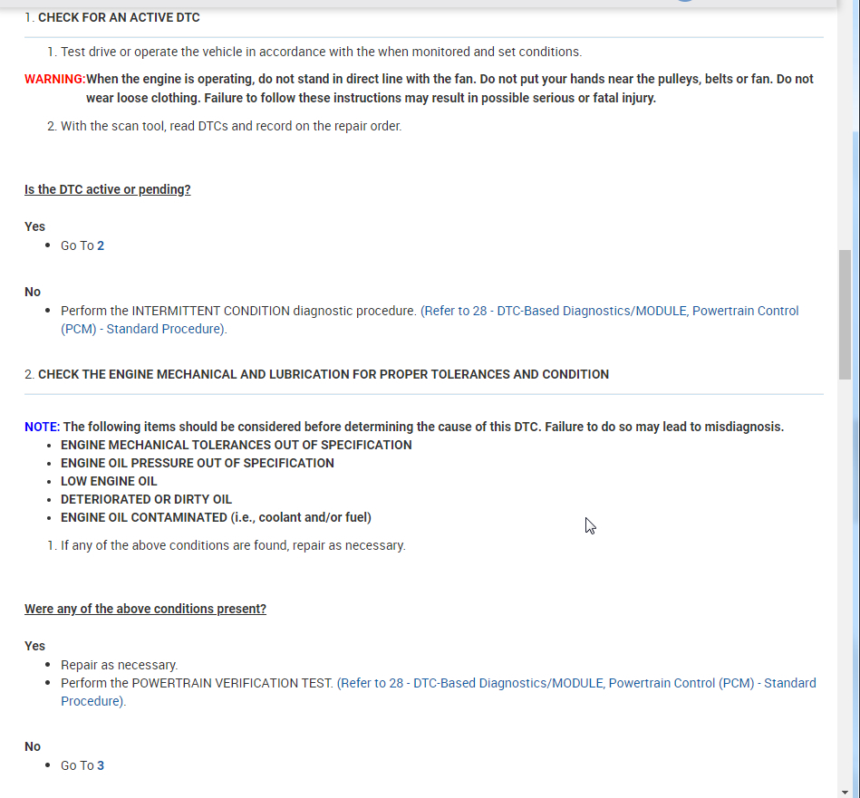
1. CHECK FOR AN ACTIVE DTC
Test drive or operate the vehicle in accordance with the when monitored and set conditions.
WARNING:
When the engine is operating, do not stand in direct line with the fan. Do not put your hands near the pulleys, belts or fan. Do not wear loose clothing. Failure to follow these instructions may result in possible serious or fatal injury.
With the scan tool, read DTCs and record on the repair order.
Is the DTC active or pending?
Yes
Go To 2
No
Perform the INTERMITTENT CONDITION diagnostic procedure. (Refer to 28 - DTC-Based Diagnostics/MODULE, Powertrain Control (PCM) - Standard Procedure).
2. CHECK THE ENGINE MECHANICAL AND LUBRICATION FOR PROPER TOLERANCES AND CONDITION
NOTE: The following items should be considered before determining the cause of this DTC. Failure to do so may lead to misdiagnosis.
ENGINE MECHANICAL TOLERANCES OUT OF SPECIFICATION
ENGINE OIL PRESSURE OUT OF SPECIFICATION
LOW ENGINE OIL
DETERIORATED OR DIRTY OIL
ENGINE OIL CONTAMINATED (i.e., coolant and/or fuel)
If any of the above conditions are found, repair as necessary.
Were any of the above conditions present?
Yes
Repair as necessary.
Perform the POWERTRAIN VERIFICATION TEST. (Refer to 28 - DTC-Based Diagnostics/MODULE, Powertrain Control (PCM) - Standard Procedure).
No
Go To 3
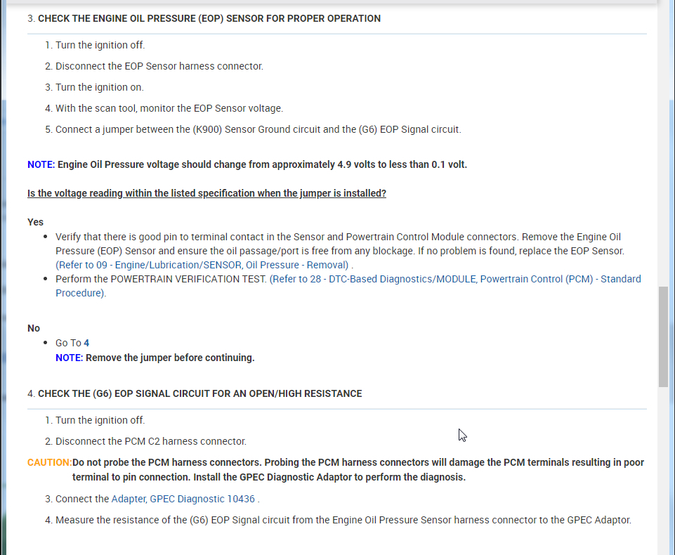
3. CHECK THE ENGINE OIL PRESSURE (EOP) SENSOR FOR PROPER OPERATION
Turn the ignition off.
Disconnect the EOP Sensor harness connector.
Turn the ignition on.
With the scan tool, monitor the EOP Sensor voltage.
Connect a jumper between the (K900) Sensor Ground circuit and the (G6) EOP Signal circuit.
NOTE: Engine Oil Pressure voltage should change from approximately 4.9 volts to less than 0.1 volt.
Is the voltage reading within the listed specification when the jumper is installed?
Yes
Verify that there is good pin to terminal contact in the Sensor and Powertrain Control Module connectors. Remove the Engine Oil Pressure (EOP) Sensor and ensure the oil passage/port is free from any blockage. If no problem is found, replace the EOP Sensor. (Refer to 09 - Engine/Lubrication/SENSOR, Oil Pressure - Removal) .
Perform the POWERTRAIN VERIFICATION TEST. (Refer to 28 - DTC-Based Diagnostics/MODULE, Powertrain Control (PCM) - Standard Procedure).
No
Go To 4
NOTE: Remove the jumper before continuing.
4. CHECK THE (G6) EOP SIGNAL CIRCUIT FOR AN OPEN/HIGH RESISTANCE
Turn the ignition off.
Disconnect the PCM C2 harness connector.
CAUTION:
Do not probe the PCM harness connectors. Probing the PCM harness connectors will damage the PCM terminals resulting in poor terminal to pin connection. Install the GPEC Diagnostic Adaptor to perform the diagnosis.
Connect the Adapter, GPEC Diagnostic 10436 .
Measure the resistance of the (G6) EOP Signal circuit from the Engine Oil Pressure Sensor harness connector to the GPEC Adaptor.
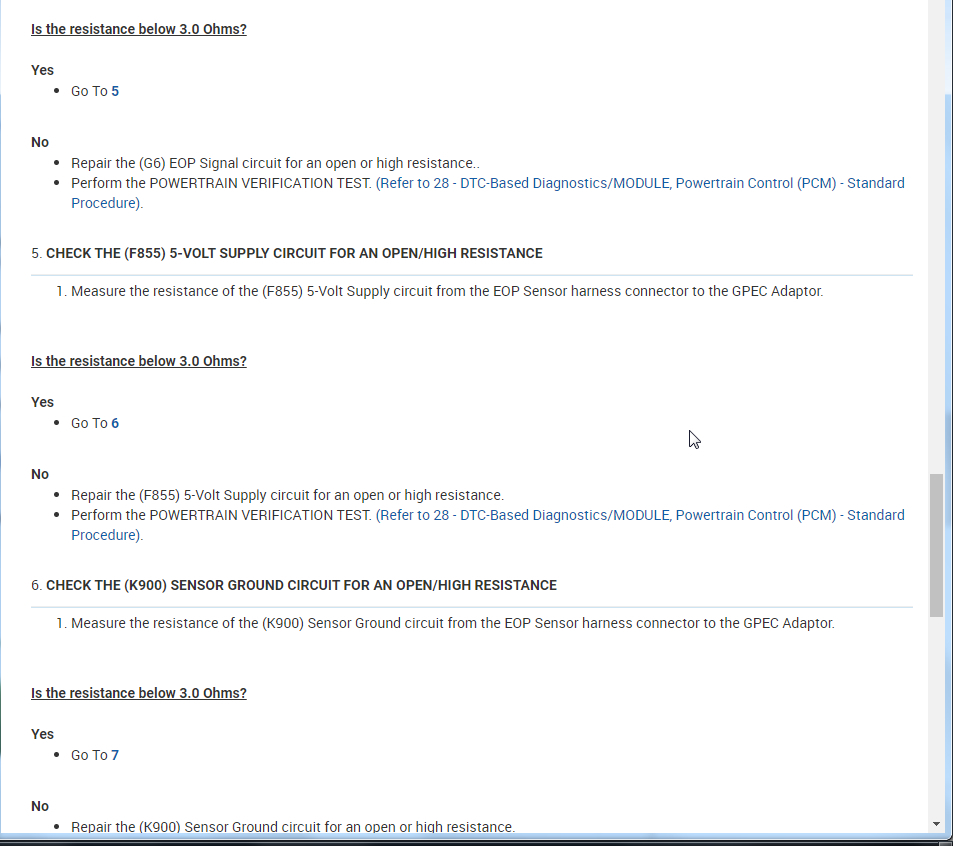
Is the resistance below 3.0 Ohms?
Yes
Go To 5
No
Repair the (G6) EOP Signal circuit for an open or high resistance..
Perform the POWERTRAIN VERIFICATION TEST. (Refer to 28 - DTC-Based Diagnostics/MODULE, Powertrain Control (PCM) - Standard Procedure).
5. CHECK THE (F855) 5-VOLT SUPPLY CIRCUIT FOR AN OPEN/HIGH RESISTANCE
Measure the resistance of the (F855) 5-Volt Supply circuit from the EOP Sensor harness connector to the GPEC Adaptor.
Is the resistance below 3.0 Ohms?
Yes
Go To 6
No
Repair the (F855) 5-Volt Supply circuit for an open or high resistance.
Perform the POWERTRAIN VERIFICATION TEST. (Refer to 28 - DTC-Based Diagnostics/MODULE, Powertrain Control (PCM) - Standard Procedure).
6. CHECK THE (K900) SENSOR GROUND CIRCUIT FOR AN OPEN/HIGH RESISTANCE
Measure the resistance of the (K900) Sensor Ground circuit from the EOP Sensor harness connector to the GPEC Adaptor.
Is the resistance below 3.0 Ohms?
Yes
Go To 7
No
Repair the (K900) Sensor Ground circuit for an open or high resistance.
Perform the POWERTRAIN VERIFICATION TEST. (Refer to 28 - DTC-Based Diagnostics/MODULE, Powertrain Control (PCM) - Standard Procedure).
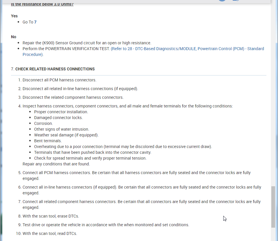
7. CHECK RELATED HARNESS CONNECTIONS
Disconnect all PCM harness connectors.
Disconnect all related in-line harness connections (if equipped).
Disconnect the related component harness connectors.
Inspect harness connectors, component connectors, and all male and female terminals for the following conditions:
Proper connector installation.
Damaged connector locks.
Corrosion.
Other signs of water intrusion.
Weather seal damage (if equipped).
Bent terminals.
Overheating due to a poor connection (terminal may be discolored due to excessive current draw).
Terminals that have been pushed back into the connector cavity.
Check for spread terminals and verify proper terminal tension.
Repair any conditions that are found.
Connect all PCM harness connectors. Be certain that all harness connectors are fully seated and the connector locks are fully engaged.
Connect all in-line harness connectors (if equipped). Be certain that all connectors are fully seated and the connector locks are fully engaged.
Connect all related component harness connectors. Be certain that all connectors are fully seated and the connector locks are fully engaged.
With the scan tool, erase DTCs.
Test drive or operate the vehicle in accordance with the when monitored and set conditions.
With the scan tool, read DTCs.
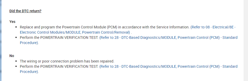
Did the DTC return?
Yes
Replace and program the Powertrain Control Module (PCM) in accordance with the Service Information. (Refer to 08 - Electrical/8E - Electronic Control Modules/MODULE, Powertrain Control/Removal) .
Perform the POWERTRAIN VERIFICATION TEST. (Refer to 28 - DTC-Based Diagnostics/MODULE, Powertrain Control (PCM) - Standard Procedure).
No
The wiring or poor connection problem has been repaired.
Perform the POWERTRAIN VERIFICATION TEST. (Refer to 28 - DTC-Based Diagnostics/MODULE, Powertrain Control (PCM) - Standard Procedure).
Images (Click to enlarge)
Nov 21, 2020 at 8:54 AM