
Air intake chamber and intake manifold must be removed for access to knock sensors. Knock sensors are located on cylinder block, just below cylinder heads. See Fig. 3 -5.
Remove caps, windshield wiper arm nuts and windshield wiper arms. Remove top seal from cowl top panel. See Fig. 12 . Remove cowl top panel cap.
Remove clip and disconnect hose for each washer nozzle. Remove driver's side and passenger's side ventilation louvers. See Fig. 12 . Remove bolts from cowl top panel. Disconnect electrical connector for windshield wiper motor. Remove cowl top panel.
Fig. 12: Locating Cowl Top Panel & Components (Sienna)
Courtesy of TOYOTA MOTOR SALES, U.S.A., INC.
Release fuel pressure. See FUEL SYSTEM PRESSURE RELEASE under FUEL SYSTEM. Drain cooling system. Remove air cleaner hose with air cleaner upper cap. See Fig. 13 . Remove "V" bank cover.
Remove bolts and engine mount support brace for engine mount at timing belt end of engine. Engine mount support brace fits from top of coolant housing to the engine mount.
Remove spark plug wire assembly. Disconnect control cables, electrical connectors, vacuum hoses and coolant hoses at throttle body. Disconnect electrical connectors and vacuum hoses from vacuum switching valves on emission control valve set located on side of air intake chamber. See Fig. 13 .
Remove nuts and disconnect power steering pressure tube from engine hanger. Disconnect necessary electrical connectors, ground straps, air hoses and vacuum hoses for removal of air intake chamber and intake manifold. Disconnect PCV hose from PCV valve on rear cylinder head.
Remove bolts, engine hanger and air intake chamber support brace from air intake chamber. Remove bolts/nuts, air intake chamber and gasket.
Note location of electrical connectors on fuel injectors for installation reference. Disconnect electrical connectors at fuel injectors. Remove fuel inlet pipe-to-fuel filter union bolt with gaskets, and disconnect fuel inlet pipe from top of fuel filter. See Fig. 13 .
Disconnect hose for air assist assembly at throttle body. Disconnect coolant hoses at intake manifold. Remove bolts/nuts and intake manifold with fuel injectors and fuel rails as an assembly. Remove gaskets for intake manifold.
Disconnect electrical connectors and hoses for removal of coolant housing. Coolant housing is located on cylinder block, in front of intake manifold area. See Fig. 13 . Remove bolts/nuts, coolant housing and gaskets. Disconnect electrical connectors at knock sensors. Using Socket (SST 09817-16011), remove knock sensor(s) from cylinder block.
Installation
Install and tighten knock sensor(s) to specification. See TORQUE SPECIFICATIONS .
To install remaining components, reverse removal procedure using NEW gaskets. Tighten bolts/nuts and fuel inlet pipe-to-fuel filter union bolt to specification. See TORQUE SPECIFICATIONS .
Ensure intake manifold bolts/nuts are tightened to specification in sequence. See Fig. 8 . Ensure coolant housing bolts/nuts are retightened to specification once intake manifold is installed and bolts/nuts are tightened to specification.
Fill cooling system. Install negative battery cable. Operate fuel pump and check for fuel leaks. See FUEL PUMP OPERATION under FUEL SYSTEM in appropriate BASIC TESTING article.
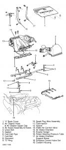
Fig. 13: Exploded View Of Air Intake Chamber & Fuel Rail Components (Sienna)
Was this helpful?
Yes
No
-1
Friday, June 25th, 2021 AT 12:51 PM
(Merged)


