Good morning,
This code could be the MAP sensor but needs to be confirmed. You need to verify voltage to the sensor and the sensor operation. Make sure the vacuum line is attached and has vacuum at idle.
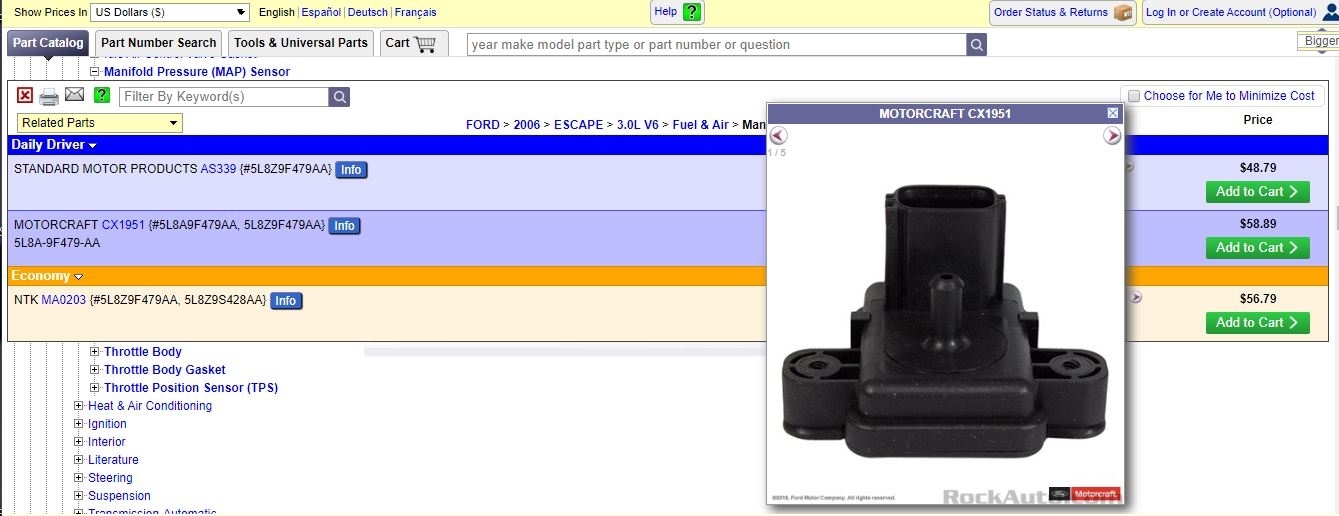
I attached a picture of the part from rock auto.
I also attached a flow chart for you to follow. If you have a scan tool, that would make it easier.
Roy
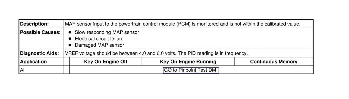
P0106
Descriptor
Probable Causes
Electrical Circuit Failure
Manifold Absolute Pressure (MAP) Sensor Damaged
Manifold Absolute Pressure (MAP) Sensor Slow Responding
Flow chart for 106.
DM15 DTC P0106: MAP RANGE/PERFORMANCE
Note:If MAP DTC(s) P0107, P0108 or P0109 are present, diagnose those DTC(s) first. If any mass air flow (MAF) sensor related DTCs are present, diagnose those DTCs prior to diagnosing MAP DTC P0106. Disregard any DTC(s) generated as a result of this test.
- Key in OFF position.
- ESM connector disconnected.
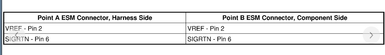
- Connect a 5 amp fused jumper wire between the following:
image
- Key ON, engine running.
- Measure the voltage between:
image
Is the voltage between 1 - 2 V?
Yes
- GO to DM19.
No
- GO to DM16.
DM16 CHECK THE MAP CIRCUIT FOR AN OPEN IN THE ESM HARNESS
- Key in OFF position.
- Remove the jumper wires.
- PCM connector disconnected.
- Measure the resistance between:
image
Is the resistance less than 5 ohms?
Yes
- GO to DM17.
No
- REPAIR the open circuit. CLEAR the DTCs. REPEAT the self-test.
DM17 CHECK THE MAP CIRCUIT FOR A SHORT IN THE ESM HARNESS
- Measure the resistance between:
image
Are the resistances greater than 10K ohms?
Yes
- GO to DM18.
No
- REPAIR the short circuit. CLEAR the DTCs. REPEAT the self-test.
DM18 KOEO AND KOER MAP VOLTAGE
Note:The MAP PID should change by at least 1.5 volts from key on engine off to key on engine running.
- Key in OFF position.
- ESM connector connected.
- PCM connector connected.
- Key ON, engine OFF.
- Access the PCM and monitor the MAP_V PID.
- Record the KOEO MAP voltage.
- Key ON, engine running.
- Access the PCM and monitor the MAP_V PID.
- Record the KOER MAP voltage.
Does the MAP PID value change?
Yes
- GO to DM19.
No
- CHECK the MAP hose for freezing or obstructions. If OK, INSTALL a new ESM. REFER to Emission Control Systems.
- CLEAR the DTCs. REPEAT the self-test.
DM19 COMPARE ACTUAL MAP VOLTAGE TO MAP PID VOLTAGE
- Key in OFF position.
- ESM connector disconnected.
- Connect a 5 amp fused jumper wire between the following:
image
- Measure the voltage between:
image
- Record the actual MAP voltage values at key on engine off, idle, 1,000 and 2,000 RPM.
- Access the PCM and monitor the MAP_V PID.
- Record the MAP PID voltage values at key on engine off, idle, 1,000 and 2,000 RPM.
Does the MAP PID voltage stay within 0.5 volt of the actual MAP voltage?
Yes
- The concern is not present at this time.
- CLEAR the DTCs. REPEAT the self-test.
No
- Carry out a visual inspection. Check for loose connections, and damaged
or corroded pins. Wiggle the harness, attempting to recreate the
concern.
- CLEAR the DTCs. REPEAT the self-test.
DM20 KOEO AND KOER DTCS P0106, P0107 AND P0108: CHECK THE VOLTAGE BETWEEN VREF AND SIGRTN AT THE MAP SENSOR
- MAP Sensor connector disconnected.
- Key ON, engine OFF.
- Measure the voltage between:
image
Is the voltage between 4.5 - 5.5 V?
Yes
- GO to DM22.
No
- GO to DM21.
DM21 CHECK FOR VREF VOLTAGE AT THE SENSOR
- Measure the voltage between:
image
Is the voltage between 4.5 - 5.5 V?
Yes
- REPAIR the open SIGRTN circuit.
- CLEAR the DTCs. REPEAT the self-test.
No
- GO to Pinpoint Test C See: Computers and Control Systems > Pinpoint Tests > C: Reference Voltage - Introduction.
DM22 CHECK MAP SIGNAL VOLTAGE AT THE SENSOR
- Measure the voltage between:
image
Is the voltage between 4.5 - 5.5 V?
Yes
- GO to DM24.
No
- GO to DM23.
DM23 CHECK THE MAP CIRCUIT(S) FOR AN OPEN IN THE HARNESS
- Key in OFF position.
- PCM connector disconnected.
- Measure the resistance between:
image
Is the resistance less than 5 ohms?
Yes
- GO to DM24.
No
- REPAIR the open circuit. CLEAR the DTCs. REPEAT the self-test.
DM24 CHECK THE MAP CIRCUIT FOR A SHORT TO VOLTAGE OR SIGRTN IN THE HARNESS
- Key in OFF position.
- PCM connector disconnected.
- Measure the resistance between:
image
Are the resistances greater than 10K ohms?
Yes
- GO to DM25.
No
- REPAIR the short circuit. CLEAR the DTCs. REPEAT the self-test.
DM25 INDUCE THE OPPOSITE SIGNAL
- PCM connector connected.
- Connect a 5 amp fused jumper wire between the following:
image
- Access the PCM and monitor the MAP_V PID.
Is the voltage less than 0.1 V?
Yes
- INSTALL a new MAP sensor. REFER to Computers and Control Systems, Electronic Engine Controls.
- CLEAR the DTCs. REPEAT the self-test.
No
- GO to DM27.
DM26 DTCS P0107, P0108 AND P0109: CHECK THE MAP CIRCUIT(S) FOR INTERMITTENT CONCERNS
- Key ON, engine OFF.
- Access the PCM and monitor the MAP_V PID.
- Carry out a thorough wiggle test on the MAP harness.
- Lightly tap on the MAP and wiggle the harness connector to simulate road shock.
Does a sudden change in voltage occur while monitoring the PID?
Yes
- GO to DM20.
No
- Unable to duplicate or identify the concern at this time.
- GO to Pinpoint Test Z See: Computers and Control Systems > Diagnostic Trouble Code Tests and Associated Procedures > Z: Intermittent - Introduction.
DM27 CHECK FOR CORRECT PCM OPERATION
- Disconnect all the PCM connectors.
- Visually inspect for:
- pushed out pins
- corrosion
- Connect all the PCM connectors and make sure they seat correctly.
- Carry out the PCM self-test and verify the concern is still present.
Is the concern still present?
Yes
- INSTALL a new PCM. REFER to Section 2, Flash Electrically Erasable Programmable Read Only Memory (EEPROM) See: Computers and Control Systems > Diagnostic Trouble Code Tests and Associated Procedures > Flash Electrically Erasable Programmable Read Only Memory (EEPROM).
No
- The system is operating correctly at this time. The concern may have been caused by a loose or corroded connector.
Images (Click to enlarge)
Sep 25, 2019 at 8:51 AM