Hi,
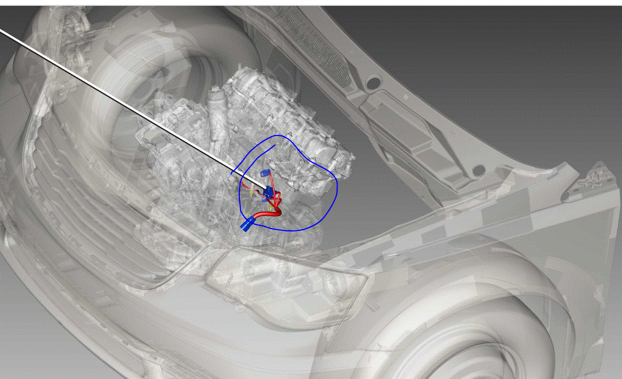
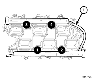
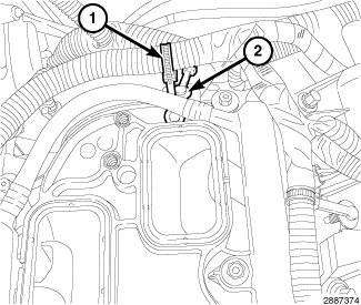
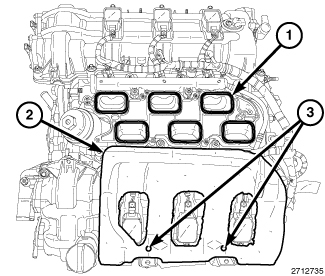
The oil pressure sensor is located under the intake manifold. They have a history of failing. Can you tell me what code was retrieved? Also, if you look at pic 1, it shows location. Note that the pic doesn't show the intake manifold.
________________________________
Here are the directions for removal and replacement. The attached pics correlate with the directions.
_______________________________
2014 Chrysler Truck Town & Country V6-3.6L
Oil Pressure Sensor - Removal
Vehicle Powertrain Management Sensors and Switches - Powertrain Management Sensors and Switches - Computers and Control Systems Oil Pressure Sensor Service and Repair Removal and Replacement Oil Pressure Sensor - Removal
OIL PRESSURE SENSOR - REMOVAL
REMOVAL
Remove the upper intake manifold and lower intake manifold (Refer to 09 - Engine/Manifolds/MANIFOLD, Intake - Removal).
Pic 2
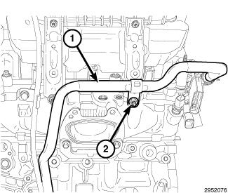
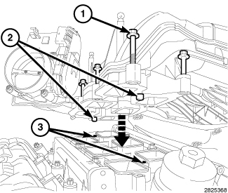
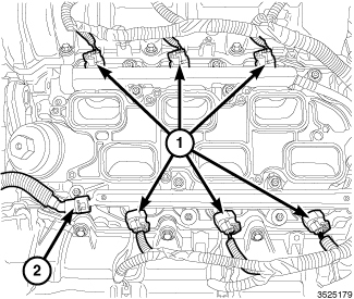
Disconnect the oil pressure sensor wire harness connector (2).
Remove the oil pressure sensor (1) from the oil filter housing.
_______________
Installation is the opposite of removal.
_______________
Here are the directions for the removal of the intake manifold. Note there is an upper and lower manifold. I will provide the directions for both.
_______________
2014 Chrysler Truck Town & Country V6-3.6L
Intake Manifold - Removal (Upper)
Vehicle Engine, Cooling and Exhaust Engine Intake Manifold Service and Repair Removal and Replacement Intake Manifold - Removal (Upper)
INTAKE MANIFOLD - REMOVAL (UPPER)
Upper Intake Manifold
pic 2
Disconnect and isolate the negative battery cable.
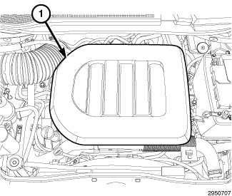
Remove the engine cover (1).
Drain the engine cooling system (Refer to 07 - Cooling - Standard Procedure)
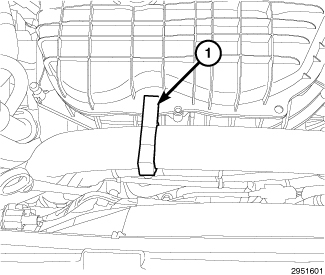
pic 3
Disengage the upper radiator hose retainer (1) from the upper intake manifold.
Remove the engine cooling fan and shroud assembly (Refer to 07 - Cooling/Engine/FAN, Cooling - Removal).
Remove the intake resonator (Refer to 09 - Engine/Air Intake System/RESONATOR, Air Cleaner - Removal).
Pic 4
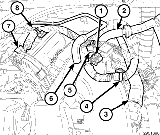
Disconnect the electrical connectors from the Manifold Absolute Pressure (MAP) sensor (1) and the Electronic Throttle Control (ETC) (7).
Disengage the ETC harness from the clip (8) on the throttle body. Disengage the wire harness retainers (4 and 5) from the upper intake manifold near the MAP sensor and reposition the wire harness.
Disconnect the following hoses from the upper intake manifold:
Positive Crankcase Ventilation (PCV) (3)
vapor purge (6)
brake booster (2)
pic 5
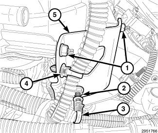
Disengage the wire harness retainer (4) from the upper intake manifold support bracket (5).
Disengage the wire harness retainer (3) from the studbolt (2).
Remove two nuts (1), loosen the studbolt (2) and reposition the upper intake manifold support bracket (5).
Pic 6
Remove the nut (2) from the support bracket of the heater core return tube (1).
Pic 7
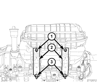
Remove two nuts (1), loosen two studbolts (3) and reposition the two upper intake manifold support brackets (2).
Pic 8
NOTE:
The upper intake manifold attaching bolts are captured in the upper intake manifold. Once loosened, the bolts will have to be lifted out of the lower intake manifold and held while removing the upper intake manifold.
NOTE:
Exercise care not to inadvertently loosen the two fuel rail attachment bolts that are in close proximity of the upper intake manifold attaching bolts.
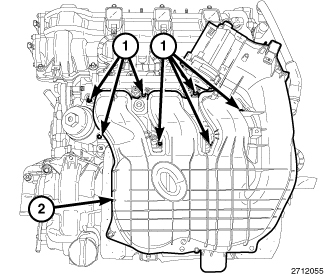
Remove seven manifold attaching bolts (1) and remove the upper intake manifold (2).
Pic 9
Remove and discard the six upper to lower intake manifold seals (1).
Cover the open intake ports to prevent debris from entering the engine.
If required, remove the insulator (2) from the LH cylinder head cover.
____________________________
Upper Install
2014 Chrysler Truck Town & Country V6-3.6L
Intake Manifold - Installation (Upper)
Vehicle Engine, Cooling and Exhaust Engine Intake Manifold Service and Repair Removal and Replacement Intake Manifold - Installation (Upper)
INTAKE MANIFOLD - INSTALLATION (UPPER)
Upper Intake Manifold
pic 10
NOTE:
Prior to installing the upper intake manifold, verify that the four fuel rail bolts were not inadvertently loosened. The bolts must tightened in the sequence shown to 7 N� m (62 in. Lbs.) (Refer to 14 - Fuel System/Fuel Delivery/RAIL, Fuel - Installation).
Pic 11
Clean and inspect the sealing surfaces. Install new upper to lower intake manifold seals (1).
NOTE:
Make sure the fuel injectors and wiring harnesses are in the correct position so that they don't interfere with the upper intake manifold installation.
If removed, install the insulator (2) to the two alignment posts (3) on top of the LH cylinder head cover.
Pic 12
Lift and hold the seven upper intake attaching bolts (1) clear of the mating surface. Back the bolts out slightly or if required, use an elastic band to hold the bolts clear of the mating surface.
Position the upper intake manifold (1) onto the lower intake manifold so that the two locating posts (2) on the upper intake manifold align with corresponding holes (3) in the lower intake manifold.
Pic 13
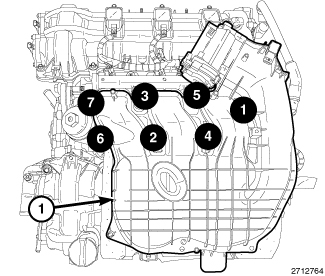
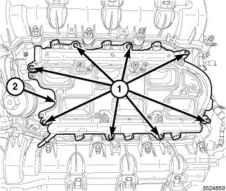
Install the seven upper intake manifold attaching bolts. Tighten the bolts in the sequence shown to 10 N� m (89 in. Lbs.).
Pic 14
Install two nuts (1) to the upper intake manifold support bracket (5). Tighten the nuts (1) to 10 N� m (89 in. Lbs.) And tighten the studbolt (2) to 20 N� m (177 in. Lbs.)
Engage the wire harness retainer (3) to the studbolt (2).
Engage the wire harness retainer (4) to the upper intake manifold support bracket (5).
Pic 15
Install two upper intake manifold support brackets (2) with two studbolts (3) and two nuts (1). Tighten the studbolts (3) to 20 N� m (177 in. Lbs.) And tighten the nuts (1) to 10 N� m (89 in. Lbs.).
Pic 16
Install the nut (2) to the support bracket of the heater core return tube (1) and tighten to 12 N� m (106 in. Lbs.).
Pic 17
Connect the following hoses to the upper intake manifold:
Positive Crankcase Ventilation (PCV) (3)
vapor purge (6)
brake booster (2)
Connect the electrical connectors to the Manifold Absolute Pressure (MAP) sensor (1) and the Electronic Throttle Control (ETC) (7).
Secure the ETC harness to the clip (7) on the throttle body and engage the wire harness retainers (4 and 5) to the upper intake manifold near the MAP sensor.
Pic 18
Install the engine cooling fan and shroud assembly (Refer to 07 - Cooling/Engine/FAN, Cooling - Installation).
Engage the upper radiator hose retainer (1) to the upper intake manifold.
Install the intake resonator (Refer to 09 - Engine/Air Intake System/RESONATOR, Air Cleaner - Installation).
Pic 19
Connect the negative battery cable and tighten nut to 5 N� m (45 in. Lbs.).
Fill the cooling system (Refer to 07 - Cooling - Standard Procedure).
Run the engine until it reaches normal operating temperature. Check cooling system for correct fluid level (Refer to 07 - Cooling - Standard Procedure)
Install the engine cover (1).
_____________________________________
Lower intake removal
LOWER INTAKE MANIFOLD
Release the fuel system pressure (Refer to 14 - Fuel System/Fuel Delivery - Standard Procedure).
Remove the resonator and upper intake manifold (Refer to 09 - Engine/Manifolds/MANIFOLD, Intake - Removal).
Pic 20
Remove the insulator (2) from the LH cylinder head cover.
Pic 21
Disconnect the fuel supply hose (2) from the fuel rail inlet (Refer to 14 - Fuel System/Fuel Delivery/FITTING, Quick Connect - Standard Procedure).
Disconnect the fuel injector electrical connectors (1).
Pic 22
Disengage the injection/ignition harness retainer (1) from the rear of the lower intake manifold.
Disengage the main wire harness retainer (2) from the rear of the lower intake manifold.
Pic 23
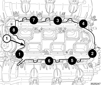
Remove the eight lower intake manifold attaching bolts (1).
Remove the lower intake manifold (2) with the fuel injectors and fuel rail.
Pic 24
Remove and discard the six lower intake manifold to cylinder head seals (1).
If required, remove the fuel rail and fuel injectors from the lower intake manifold (Refer to 14 - Fuel System/Fuel Delivery/RAIL, Fuel - Removal).
______________________________
Lower Install
2014 Chrysler Truck Town & Country V6-3.6L
Intake Manifold - Installation (Lower)
Vehicle Engine, Cooling and Exhaust Engine Intake Manifold Service and Repair Removal and Replacement Intake Manifold - Installation (Lower)
INTAKE MANIFOLD - INSTALLATION (LOWER)
LOWER INTAKE MANIFOLD
pic 25
Clean and inspect the sealing surfaces. Install new lower intake manifold to cylinder head seals (1).
If removed, install the fuel injectors and the fuel rail to the lower intake manifold (Refer to 14 - Fuel System/Fuel Delivery/RAIL, Fuel - Installation)
pic 26
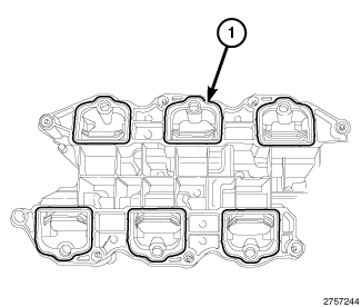
Position the lower intake manifold (1) on the cylinder head surfaces.
Tighten the bolts to the proper (Torque Specifications) in the sequence shown.
Pic 27
Engage the main wire harness retainer (2) to the rear of the lower intake manifold.
Engage the injection/ignition harness retainer (1) to the rear of the lower intake manifold.
Pic 28
Connect the fuel injector harness connectors (1).
Connect the fuel supply hose (2) to the fuel rail (Refer to 14 - Fuel System/Fuel Delivery/FITTING, Quick Connect - Standard Procedure).
Pic 29
Install the insulator (2) to the two alignment posts (3) on top of the LH cylinder head cover.
Install the upper intake manifold, support brackets and resonator (Refer to 09 - Engine/Manifolds/MANIFOLD, Intake - Installation).
Start the engine and check for leaks.
______________________________
Let me know if this helps or if you have other questions.
Take care,
Joe
Images (Click to make bigger)
Tuesday, December 8th, 2020 AT 4:03 PM