Welcome to 2carpros.com
If you are getting motor oil in the coolant, it sounds like a head gasket. Even though you are not seeing coolant mixing with oil doesn't mean the gasket isn't the issue. You mentioned that the coolant level dropped. Was there any white smoke from the exhaust when the engine is running that could indicate coolant is now being burned in the combustion chamber?
Take a look through this link. It explains how to identify a bad head gasket. See if it helps or mirrors what you have seen happen thus far.
https://www.2carpros.com/articles/head-gasket-blown-test
If you find that it is the gasket, here are the directions for removing and replacing the cylinder head which will include timing, torque specs, and so on. I realize you are not replacing the head, but the directions are for removal and replacement. Obviously, you will be replacing the gasket and not the entire head, unless you find a crack or other non-repairable issue. All attached pics correlate with the directions.
__________________________________________
2012 Chevrolet Cruze L4-1.8L
Cylinder Head Replacement
Vehicle Engine, Cooling and Exhaust Engine Cylinder Head Assembly Service and Repair Removal and Replacement Cylinder Head Replacement
CYLINDER HEAD REPLACEMENT
Cylinder Head Replacement
Special Tools
^ EN-6333 Timing Belt Tensioner Locking Pin
^ EN-6340 Camshaft Adjuster Locking Tool
^ EN-6625 Crankshaft Locking Device
^ EN-6628-A Camshaft Locking Tool
^ EN-45059 Angle Meter
For equivalent regional tools, refer to Special Tools.
Removal Procedure
1. Disconnect the battery negative cable. See: Negative > Removal and Replacement
2. Remove the air cleaner assembly.
3. Raise and support the vehicle. See: Vehicle Lifting > Procedures
4. Drain the cooling system. See: Cooling System > Procedures
5. Drain the engine oil. See: Engine Oil > Removal and Replacement
6. Remove the intake manifold. See: Intake Manifold > Removal and Replacement
pic 1
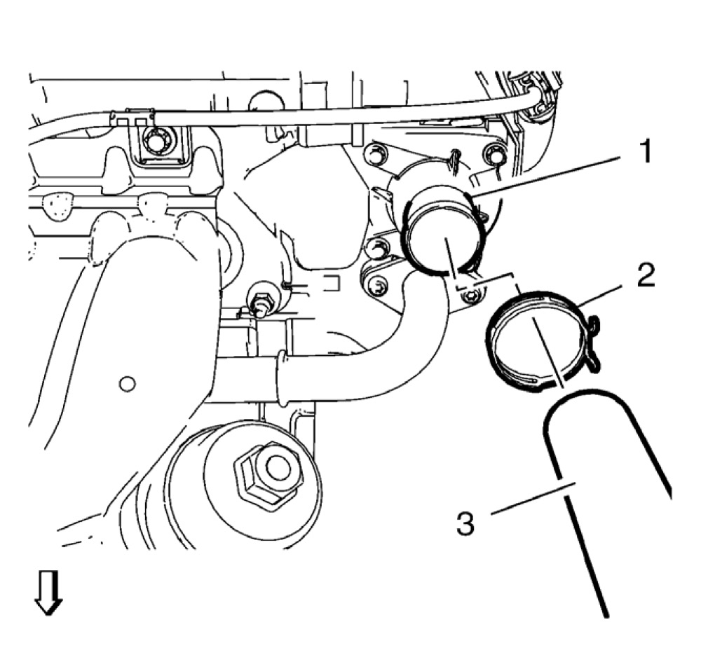
7. Loosen the radiator inlet hose clamp (2).
8. Remove the radiator inlet hose (3) from the engine coolant thermostat (1).
9. Remove the heater outlet hose from the engine coolant thermostat housing.
10. Remove the heater inlet hose from the engine coolant thermostat housing.
pic 2
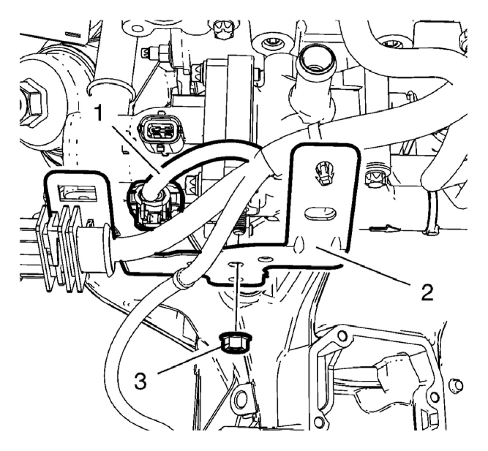
11. Disconnect the thermostat wiring harness plug (1).
12. Remove the thermostat housing bracket nut (3).
13. Hang the thermostat housing bracket (2) with attached wiring harness aside.
14. Remove the exhaust manifold. See: Exhaust Manifold > Removal and Replacement
pic 3
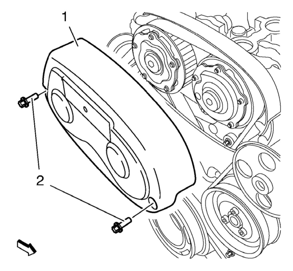
15. Remove the 2 timing belt upper front cover bolts (2).
16. Remove the timing belt upper front cover (1).
17. Remove the camshaft cover. See: Engine > Overhaul
18. Remove the 2 camshaft position sensor. See: Camshaft Position Sensor > Removal and Replacement
19. Remove the 2 camshaft position actuator solenoid valve. See: Camshaft, Engine > Removal and Replacement
20. Remove the drive belt tensioner. See: Engine > Overhaul
pic 4
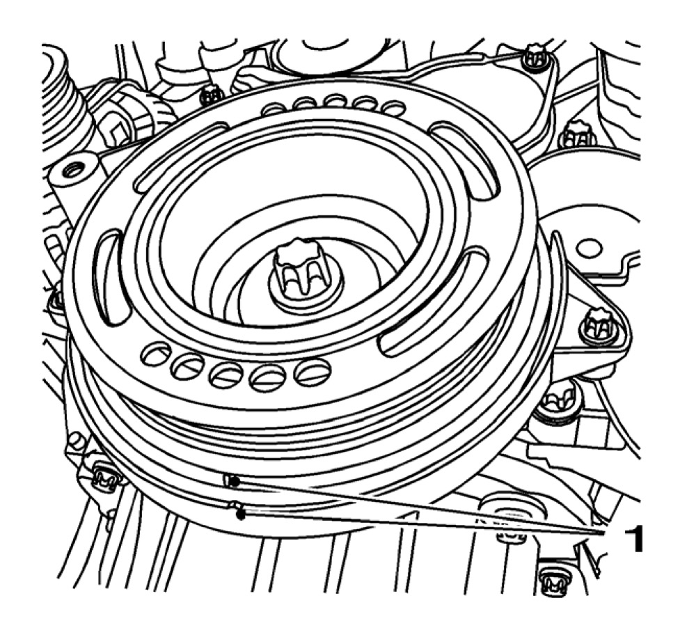
21. Set the crankshaft balancer in direction of engine rotation until the markings (1) line up with the cylinder 1 at TDC.
22. Remove the crankshaft balancer. See: Engine > Overhaul
pic 5
23. Remove the 4 lower timing belt cover bolts (2).
24. Remove the lower timing belt cover (1).
25. Lower the vehicle.
26. Support the engine under the oil pan.
pic 6
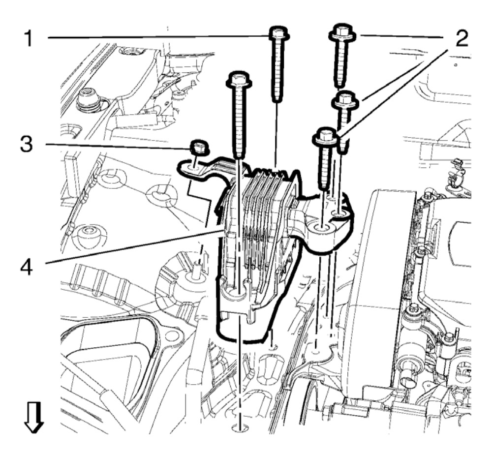
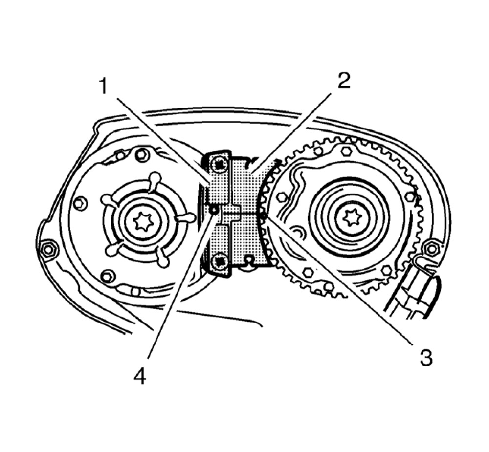
27. Remove the engine mount nut (3).
28. Remove the 5 engine mount bolts (1, 2).
29. Remove the engine mount (4).
pic 7
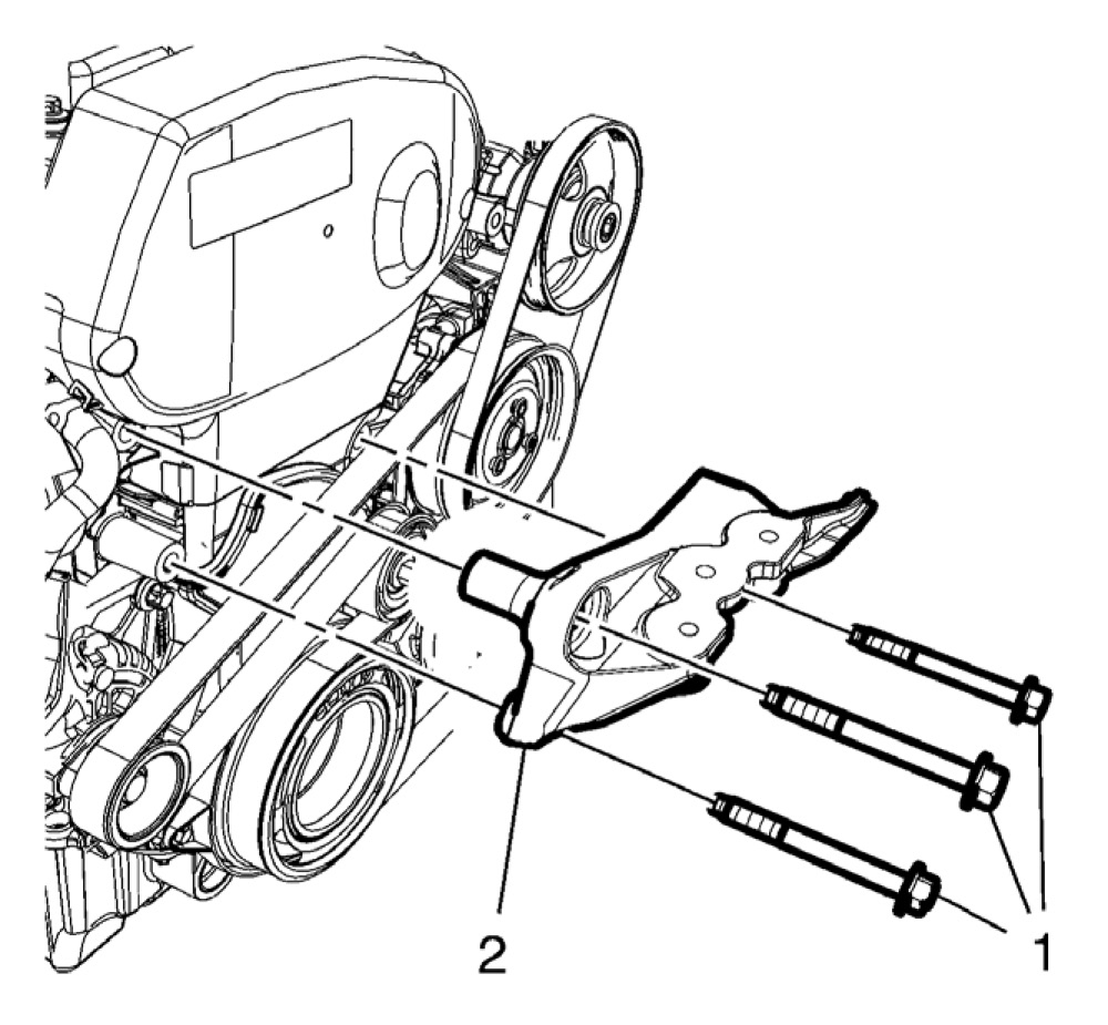
30. Remove the 3 engine mount bracket bolts (1).
31. Remove the engine mount bracket (2).
pic 8
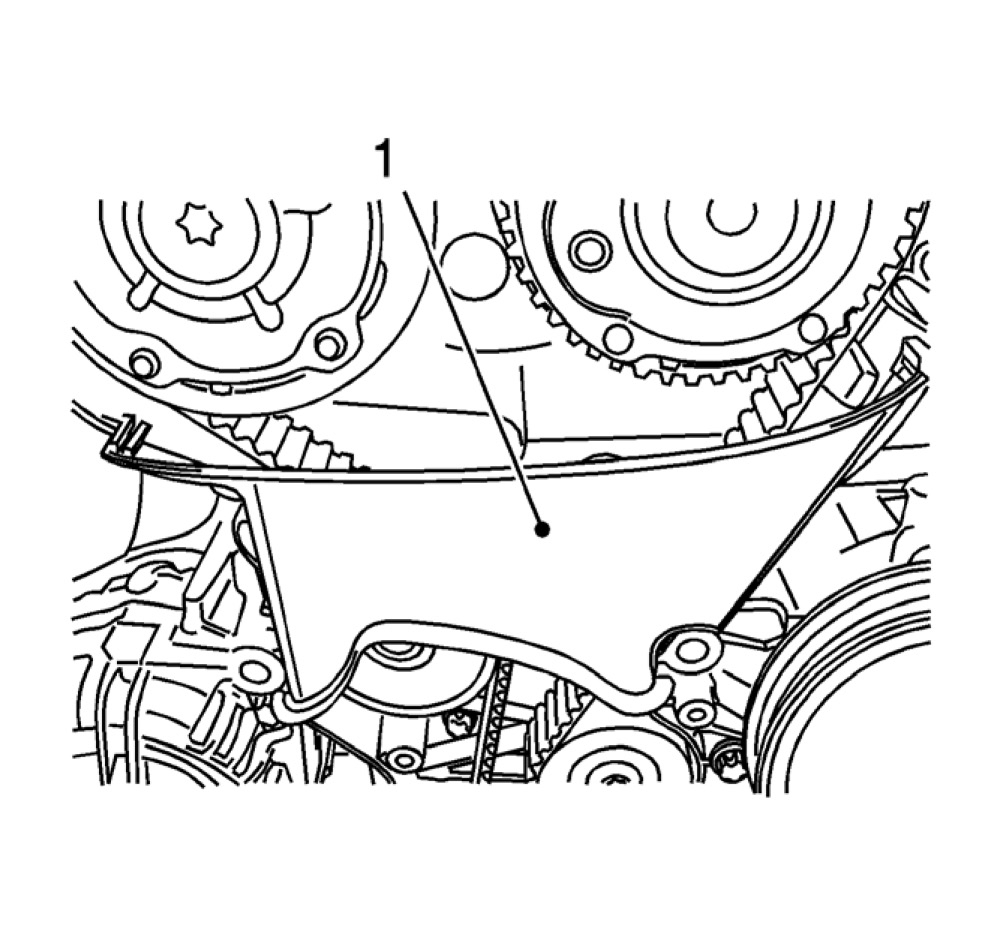
32. Remove the center front timing belt cover from the rear timing belt cover at 2 locations.
33. Remove the center front timing belt cover (1).
pic 9
34. Install the EN-6340 locking tool into the camshaft adjusters.
Note: The spot type marking (4) on the intake camshaft adjuster does not correspond to the groove of EN-6340 locking tool - left during this process but must be somewhat above as shown.
^ Install the EN-6340 locking tool - left (1) in the camshaft adjusters as shown.
Note: The spot type marking (3) on the exhaust camshaft adjuster must correspond to the groove on EN-6340 locking tool - right.
^ Install EN-6340 locking tool - right (2) in the camshaft adjusters as shown.
pic 10
35. Apply tension to the timing belt tensioner (2) in the direction of the arrow, using an allen key (1).
36. Install the EN-6333 pin (3).
pic 11
Note: Note the direction of the belt, if the timing belt will be reused.
37. Remove the timing belt (1).
38. Remove and DISCARD the timing belt tensioner bolt (3).
39. Remove the timing belt tensioner (2).
40. Raise the vehicle.
pic 12
41. Remove the timing belt idler pulley bolt (1).
42. Remove the timing belt idler pulley (2).
43. Remove the EN-6625 locking device.
pic 13
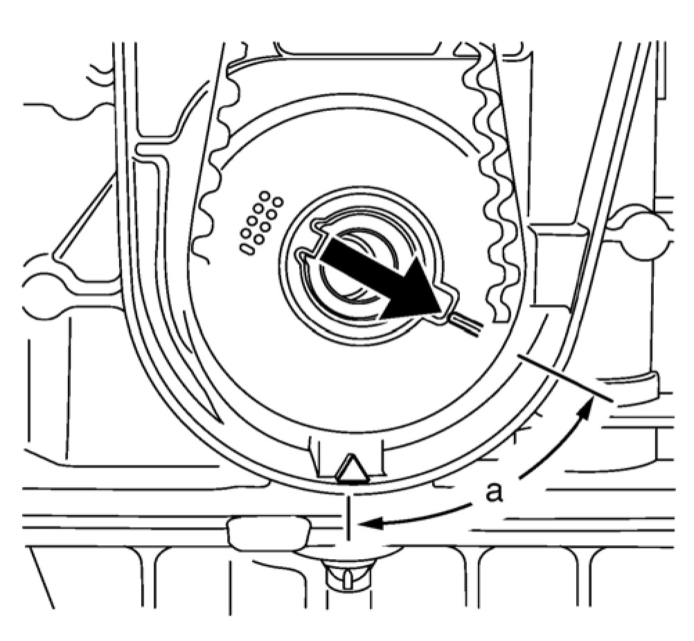
44. Set the crankshaft in direction of engine rotation to 60 degrees (a) before TDC. Use the EN-45059 meter and the crankshaft balancer bolt.
pic 14
Note: Some engine oil will run out of the camshaft and the camshaft position actuator adjuster. That is the reason for the removal of the whole timing assembly.
45. Remove the crankshaft sprocket (1).
46. Lower the vehicle.
47. Remove the EN-6340 locking tool.
pic 15
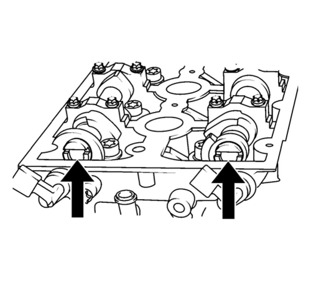
Note: Note the arrows.
48. Turn the camshaft by the camshaft position actuator adjuster until the groove on the end of the camshafts is horizontal.
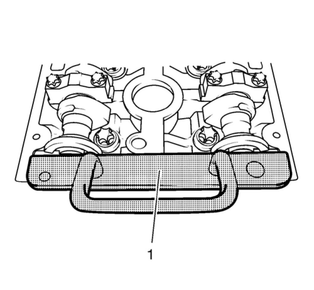
pic 16
49. Install the EN-6628-A locking tool (1).
50. Place a collecting basin underneath the vehicle.
pic 17
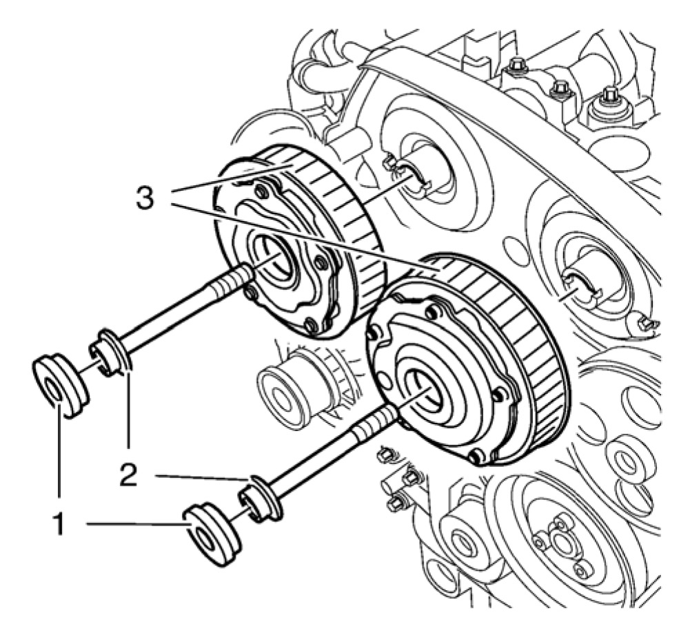
51. Remove the camshaft position actuator adjuster closure bolt (1) of the intake camshaft position actuator adjuster and the exhaust camshaft position actuator adjuster (3).
Note: A second technician is required.
Note: Use an appropriate open-end wrench in order to counterhold the camshaft hexagon. A thin cross-section wrench is required for a better fit. The usage of EN-6628-A locking tool is for the camshaft adjustment to prevent misalignment of the camshafts. The wrench is required to counterhold the camshafts during bolt torque procedure.
52. Remove and DISCARD the intake camshaft position actuator adjuster bolt and/or the exhaust camshaft position actuator adjuster bolt (2).
53. Remove the intake camshaft position actuator adjuster and the exhaust camshaft position actuator adjuster (3).
54. Remove the timing belt rear cover. See: Engine > Overhaul
pic 18
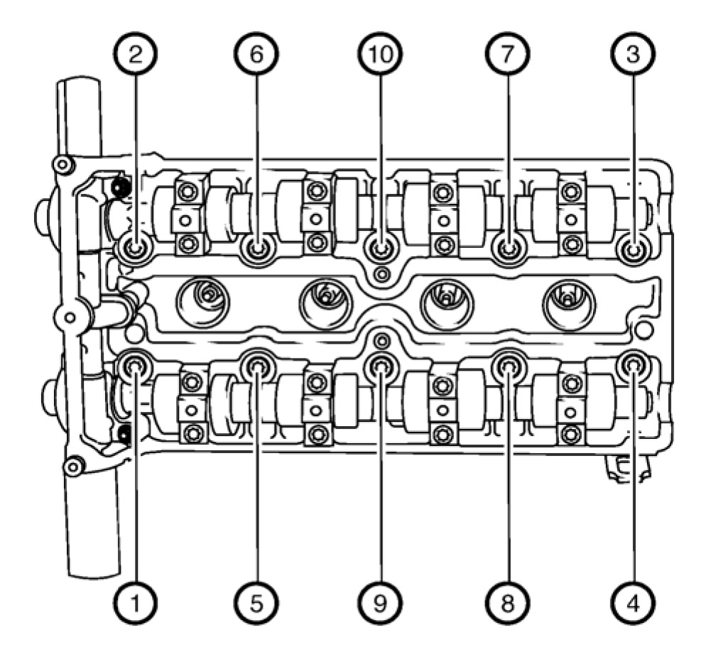
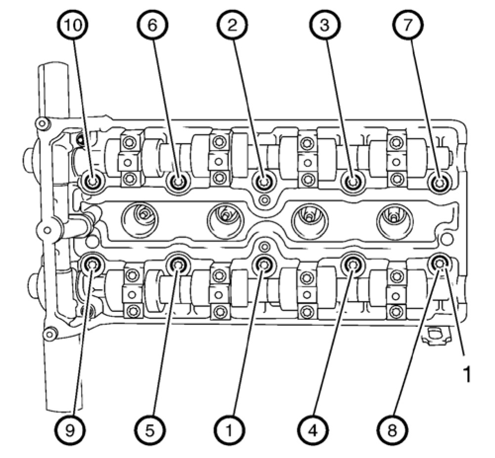
55. Loosen the 10 cylinder head bolts in sequence as shown.
55.1. Loosen the 10 bolts 90 degrees.
55.2. Loosen the 10 bolts 180 degrees.
pic 19
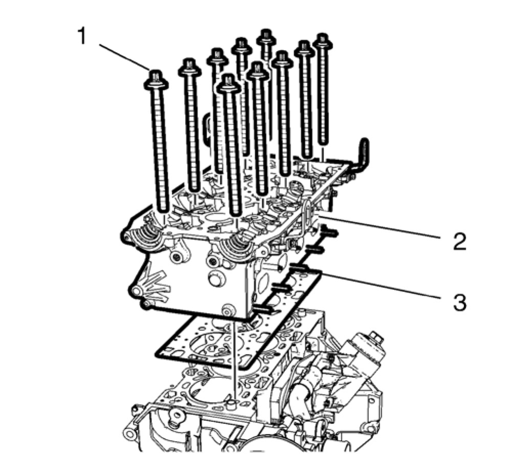
56. Remove and DISCARD the 10 cylinder head bolts (1).
57. Remove the cylinder head (2).
58. Remove and DISCARD the cylinder head gasket (3).
59. In case of re-use, then clean and inspect the cylinder head. See: Engine > Overhaul
60. Remove the thermostat housing. See: Engine > Overhaul
61. Remove the camshafts. See: Engine > Overhaul
62. Remove the valve lifter. See: Engine > Overhaul
63. Disassemble the cylinder head. See: Engine > Overhaul
Installation Procedure
1. Assemble the cylinder head. See: Engine > Overhaul
2. Install the valve lifter. See: Engine > Overhaul
3. Install the camshafts. See: Engine > Overhaul
4. Install the thermostat housing. See: Engine > Overhaul
5. Clean the sealing surfaces.
6. Inspect for plane surface.
^ Cylinder block, cylinder head
^ Straight-edge, feeler gauge
pic 20
7. Install a NEW cylinder head gasket (3).
8. Install the cylinder head (2).
Caution: Refer to Fastener Caution.
Caution: Refer to Torque-to-Yield Fastener Caution.
pic 21
9. Install 10 NEW cylinder head bolts (1).
10. Tighten the bolts as shown in sequence in 5 passes, using the EN-45059 meter:
10.1. First pass to 25 N.m (18 lb ft)
10.2. Second pass to 90 degrees
10.3. Third pass to 90 degrees
10.4. Fourth pass to 90 degrees
10.5. Final pass to 45 degrees
11. Install the timing belt rear cover. See: Engine > Overhaul
pic 22
12. Align the camshafts horizontally by the hexagon arrows, until the EN-6628-A locking tool can be inserted in both camshafts.
pic 23
13. Insert the EN-6628-A locking tool (1) into the camshafts.
pic 24
Note: If the cover is contaminated with oil, you have to clean it close.
Note: A second person is required. Counterhold against the hexagon of corresponding camshaft with an open-ended wrench.
14. Install intake camshaft position actuator adjuster and/or the exhaust camshaft position actuator adjuster (3).
15. Install a NEW intake camshaft position actuator adjuster bolt and/or a NEW exhaust camshaft position actuator adjuster bolt (2).
pic 25
16. Install the EN-6340 locking tool into the camshaft position actuator adjusters.
Note: The spot type marking (4) on the intake camshaft position actuator adjuster does not correspond to the groove of EN-6340 locking tool - left during this process but must be somewhat above as shown.
16.1. Install the EN-6340 locking tool - left (1) in the camshaft position actuator adjusters as shown.
Note: The spot type marking (3) on the exhaust camshaft position actuator adjuster must correspond to the groove on EN-6340 locking tool - right.
16.2. Install the EN-6340 locking tool - right (2) in the camshaft position actuator adjusters as shown.
Caution: Refer to Torque-to-Yield Fastener Caution.
Note: If the cover is contaminated with oil, you have to clean it close.
Note: A second technician is required.
Note: Use an appropriate open-end wrench in order to counterhold the camshaft hexagon. A thin cross-section wrench is required for a better fit. The Use of EN-6628-A locking tool is for the camshaft adjustment to prevent misalignment of the camshafts. The wrench is required to counterhold the camshafts during bolt torque procedure.
17. Tighten the camshaft position actuator adjuster bolts (2) in three passes use the EN-45059 meter:
Hold at the appropriate camshaft hexagon.
17.1. First pass tighten to 50 N.m (37 lb ft).
17.2. Second pass to 150 degrees.
17.3. Final pass to 15 degrees.
Note: Check the closure bolt seal ring.
18. Install the 2 camshaft position actuator adjuster closure plugs (1) and tighten to 30 N.m (22 lb ft).
19. Remove the EN-6628-A locking tool.
pic 26
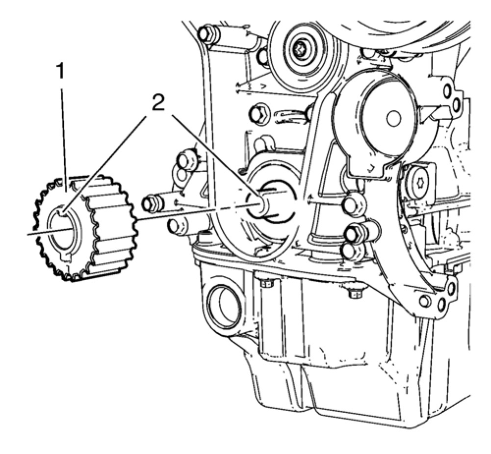
Note: When installing the crankshaft sprocket, the cam and the groove must align (2).
20. Install the crankshaft sprocket (1).
pic 27
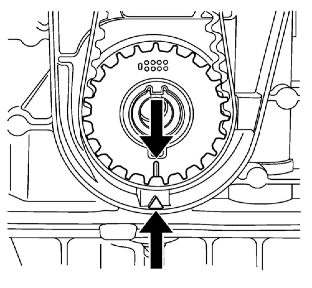
Note: The crankshaft sprocket and oil pump housing must align.
21. Set the crankshaft in the direction of engine rotation to TDC. Use the crankshaft balancer bolt.
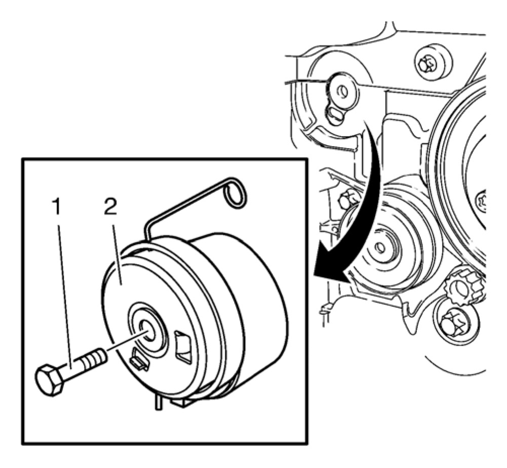
Caution: Refer to Torque-to-Yield Fastener Caution.
pic 28
22. Install the timing belt tensioner (2) and tighten the NEW timing belt tensioner bolt (1) in three passes use the EN-45059 meter:
22.1. First pass tighten to 20 N.m (15 lb ft).
22.2. Second pass to 120 degrees.
22.3. Third pass to 15 degrees.
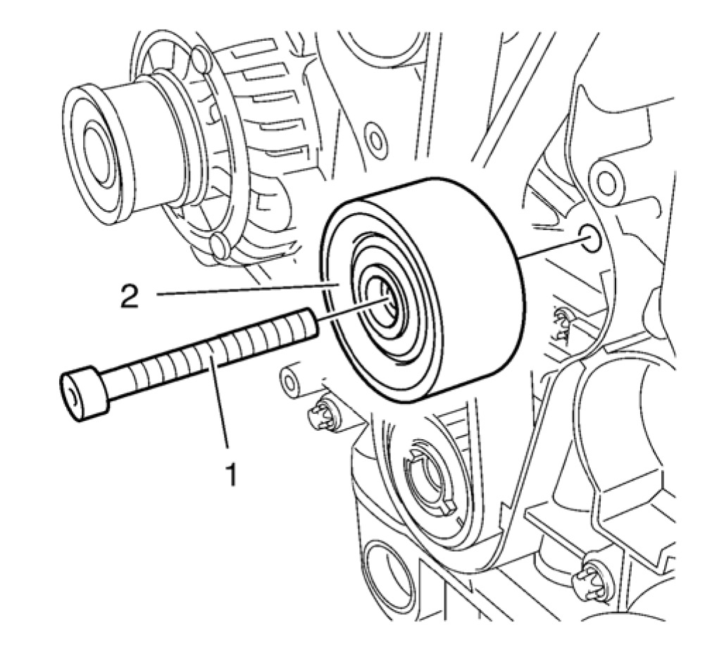
Caution: Refer to Torque-to-Yield Fastener Caution.
pic 29
23. Install the timing belt idler pulley (2) and tighten the NEW bolt (1) in three passes use the EN-45059 meter:
23.1. First pass tighten to 20 N.m (15 lb ft).
23.2. Second pass to 120 degrees.
23.3. Third pass to 15 degrees.
pic 30
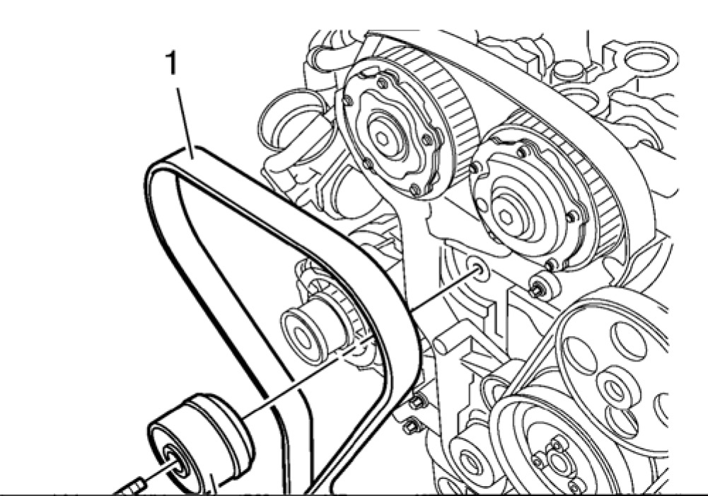
24. Install the timing belt (1).
25. Guide the timing belt past the tensioner and place it on the crankshaft sprocket wheel.
26. Place the timing belt on the exhaust and intake camshaft position actuator adjusters.
pic 31
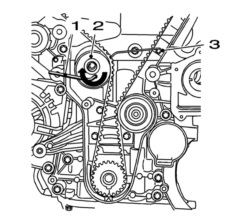
27. Apply tension to the timing belt tensioner (2) in the direction of the arrow, using an allen key (1).
28. Remove the EN-6333 pin (3).
Note: The timing belt tensioner moves automatically to the correct position.
29. Release tension on timing belt tensioner.
30. Lower the vehicle.
pic 32
31. Install the engine mount bracket (2).
32. Install the 3 engine mount bracket bolts (1) tighten to 62 N.m (46 lb ft).
pic 33
33. Install the engine mount (4).
34. Install the 2 engine mount bolts (1) and tighten to 62 N.m (46 lb ft).
Caution: Refer to Torque-to-Yield Fastener Caution.
35. Install the 3 engine mount bolts (2) and tighten in three passes use the EN-45059 meter.
35.1. First pass tighten to 50 N.m (37 lb ft).
35.2. Second pass to 60 degrees.
35.3. Third pass to 15 degrees.
36. Unsupport the engine.
37. Remove EN-6340 locking tool.
pic 34
38. Check the timing
Note: Note the marking at the camshaft sprockets.
^ Turn the crankshaft 720 degrees in the direction of engine rotation by the bolt on the crankshaft balancer.
Note: The spot type marking (4) on the intake camshaft adjuster does not correspond to the groove of EN-6340 locking tool - left during this process but must be somewhat above as shown.
^ Install EN-6340 locking tool - left (1) into the camshaft adjusters as shown.
Note: The spot type marking (3) on the exhaust camshaft adjuster must correspond to the groove on EN-6340 locking tool - right.
^ Install EN-6340 locking tool - right (2) into the camshaft adjusters as shown.
^ Raise the vehicle.
pic 35
Note: The crankshaft sprocket and oil pump housing must align.
39. Check the crankshaft position.
pic 36
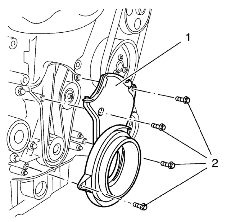
40. Install the lower timing belt cover (1).
Caution: Refer to Fastener Caution.
41. Install the 4 lower timing belt cover bolts (2) and tighten to 6 N.m (53 lb in).
42. Install the crankshaft balancer. See: Engine > Overhaul
43. Lower the vehicle.
44. Remove the EN-6340 locking tool.
45. Install the camshaft position actuator solenoid valve. See: Camshaft, Engine > Removal and Replacement
46. Install the 2 camshaft position sensors. See: Camshaft Position Sensor > Removal and Replacement
47. Install the camshaft cover. See: Engine > Overhaul
pic 37
48. Install the timing belt upper front cover (1).
49. Install the 2 timing belt upper front cover bolts (2) and tighten to 6 N.m (53 lb in).
50. Install the exhaust manifold. See: Exhaust Manifold > Removal and Replacement
pic 38
51. Install the radiator inlet hose (3) with the radiator inlet hose clamp (2) to the engine coolant thermostat (1).
52. Install the heater inlet hose to the engine coolant thermostat housing.
53. Install the heater outlet hose to the engine coolant thermostat housing.
pic 39
54. Install the engine coolant thermostat housing bracket (2).
55. Install the engine coolant thermostat housing bracket nut (3) and tighten to 6 N.m (53 lb in).
56. Connect the thermostat wiring harness plug (1).
57. Install the intake manifold. See: Intake Manifold > Removal and Replacement
58. Install the air cleaner assembly.
59. Fill engine oil. See: Engine Oil > Removal and Replacement
60. Connect the battery negative cable. See: Negative > Removal and Replacement
61. Fill the cooling system. See: Cooling System > Procedures
_____________________________
Let me know what you find or if you have other questions.
Take care,
Joe
Images (Click to enlarge)
Jul 23, 2019 at 9:16 PM