Good morning,
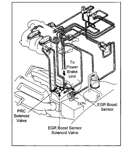
I attached a TSB on the 1195 code. Follow the TSB for the hose routings.
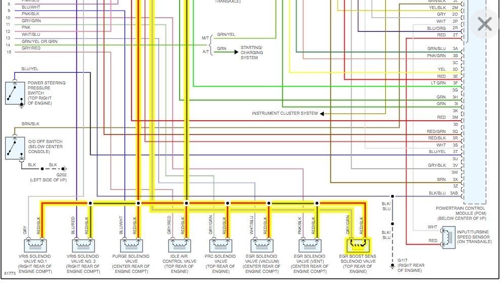
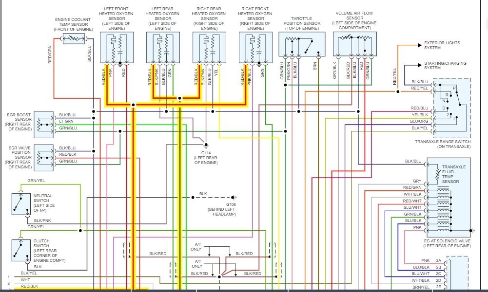
I also attached a wiring diagram of the boost solenoid as well. I would verify power to the solenoid with the key on.
https://www.2carpros.com/articles/how-to-check-wiring
Roy
Bulletin No.: 022/97
Issued: 10/23/97
Revised:
Category
F
Applicable Model/s
1996 - 97 626/MX-6 With 6 Cyl. Engine
Subject:
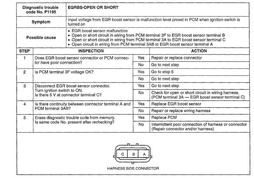
MIL ILLUMINATION AND DTC P0400 OR P1195 IS STORED IN MEMORY
APPLICABLE MODELS
1996 - 97 626 & MX-6 with 6 cylinder (V-6) engine.
DESCRIPTION
The "Malfunction Indicator Light" (MIL) may illuminate and DTC P0400 or P1195 may be stored in memory. This concern may be caused by any one of the following conditions:
Mis-routed, twisted or kinked vacuum lines
Swapped Pressure Regulator Control (PRC) and EGR Boost Sensor solenoid connectors
Defective EGR Boost Sensor
Customers complaining of this concern should have the vehicle inspected according to this bulletin and if necessary, repaired.
REPAIR PROCEDURE
1. Verify that all vacuum lines are properly routed, not kinked or twisted.
If properly routed, not kinked or twisted, proceed to step 2.
If not properly routed, repair and proceed to step 4.
imageOpen In New TabZoom/Print
2. Locate the PRC and EGR boost sensor solenoid valves on the right side of the air cleaner housing.
3. Verify correct connector placement at the PRC and EGR boost sensor solenoid.
If the connectors are not in the proper position, correct their placement and proceed to step 6.
If the connectors are in the proper position, proceed to step 4.
NOTE:
The PRC connector (top) is BROWN and the EGR boost sensor solenoid connector (bottom) is BLACK.
The 1996 wiring Diagram incorrectly shows the location of these connectors for the KL engine.
4. Inspect the EGR boost sensor.
Warm engine to normal operating temperature.
Measure the voltage between the signal wires (B/L & LG) from the rear side of the connector.
imageOpen In New TabZoom/Print
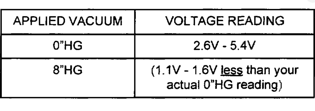
Use a vacuum pump and apply vacuum to the EGR boost sensor according to the table.
5. Record the voltage. Refer to the table shown.
If the voltage readings are not within the specified range replace boost sensor and proceed to step 6.
If no problem is found with EGR boost sensor, perform the DTC troubleshooting procedures (refer to Workshop Manual section F2).
6. Verify the repair by completing the OBD II drive mode (refer to 1995-97 OBD II Service Highlights).
Images (Click to make bigger)
Tuesday, July 14th, 2020 AT 5:22 AM