Good afternoon,
Do you have any codes stored in the system? If you do, can you list them?
The DPFE does not have vacuum. It works on pressures from the exhaust to determine exhaust flow to the converters.
The EGR will only have vacuum when the solenoid is open to pass vacuum when commanded by the ECM.
https://www.2carpros.com/articles/how-emission-control-systems-work
What is the exact issue?
Roy
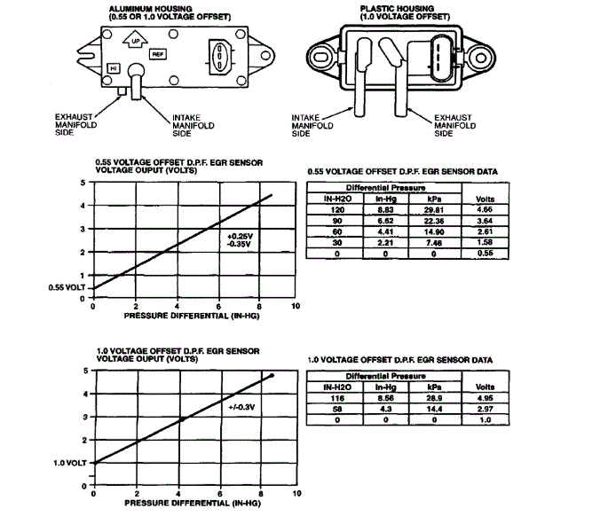
The differential pressure feedback EGR sensor will either have an aluminum housing or a black plastic housing depending on the application. Also, sensors will have either a 0.55 voltage offset or 1.0 voltage offset (the voltage offset refers to the sensor key ON engine OFF voltage). Refer to the table to identify the sensor for your application when performing Pinpoint Test HE. The part numbers shown in the table are engineering part numbers stamped on the sensor.
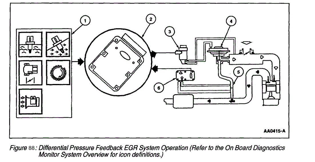
DIFFERENTIAL PRESSURE FEEDBACK EGR SYSTEM
The Differential Pressure Feedback EGR system consists of a differential pressure feedback EGR sensor, EGR vacuum regulator solenoid, EGR valve, orifice tube assembly, Powertrain Control Module (PCM) and connecting wires and vacuum hoses. Operation of the system is as follows:
1. The Differential Pressure Feedback EGR system receives signals from the Engine Coolant Temperature (ECT) sensor, Intake Air Temperature (IAT) sensor, Throttle Position (TP) sensor, Mass Air Flow (MAF) sensor and Crankshaft Position (CKP) sensor to provide information on engine operating conditions to the PCM. The engine must be warm, stable and running at a moderate load and rpm before the EGR system is activated. The PCM deactivates EGR during idle, extended wide open throttle or whenever a failure is detected in an EGR component or EGR required input.
2. The PCM calculates the desired amount of EGR flow for a given engine condition. It then determines the desired pressure drop across the metering orifice required to achieve that flow and outputs the corresponding signal to the EGR vacuum regulator solenoid.
3. The EGR vacuum regulator solenoid receives a variable duty cycle signal (0 to 100%). The higher the duty cycle the more vacuum the solenoid diverts to the EGR valve.
4. The increase in vacuum acting on the EGR valve diaphragm overcomes the valve spring and begins to lift the EGR valve pintle off its seat, causing exhaust gas to flow into the intake manifold.
5. Exhaust gas flowing through the EGR valve must first pass through the EGR metering orifice. With one side of the orifice exposed to exhaust backpressure and the other to the intake manifold, a pressure drop is created across the orifice whenever there is EGR flow. When the EGR valve closes, there is no longer flow across the metering orifice and pressure on both sides of the orifice is the same. The PCM constantly targets a desired pressure drop across the metering orifice to achieve the desired EGR flow.
6. The differential pressure feedback EGR sensor measures the actual pressure drop across the metering orifice and relays a proportional voltage signal (0 to 5 volts) to the PCM. The PCM uses this feedback signal to correct for any errors in achieving the desired EGR flow.
HARDWARE
imageOpen In New TabZoom/Print
Differential Pressure Feedback EGR Sensor
The differential pressure feedback EGR sensor is a ceramic, capacitive-type pressure transducer that monitors the differential pressure across a metering orifice located in the orifice tube assembly. The differential pressure feedback sensor receives this signal through two hoses referred to as the downstream pressure hose (REF SIGNAL) and upstream pressure hose (HI SIGNAL). The HI and REF hose connections are marked on the aluminum differential pressure feedback EGR sensor housing for identification (note that the HI signal uses a larger diameter hose). The differential pressure feedback EGR sensor outputs a voltage proportional to the pressure drop across the metering orifice and supplies it to the PCM as EGR flow rate feedback.
There are two visually distinct differential pressure feedback EGR sensors being manufactured. One is the original, aluminum-cast housing sensor found on most applications. The second is a new, plastic housing sensor designed to perform the same function. Some applications will also have a modified voltage output. Verify the sensor part number to identify the correct differential pressure feedback EGR sensor for all applications.
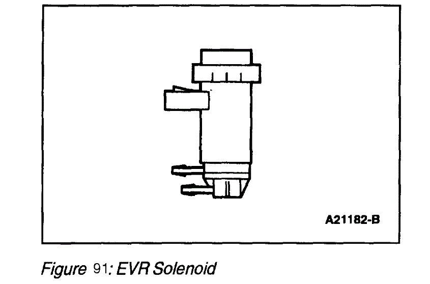
EVR Solenoid
imageOpen In New TabZoom/Print
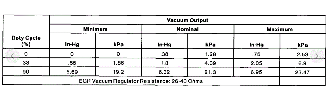
Solenoid Data
imageOpen In New TabZoom/Print
Solenoid Data
imageOpen In New TabZoom/Print
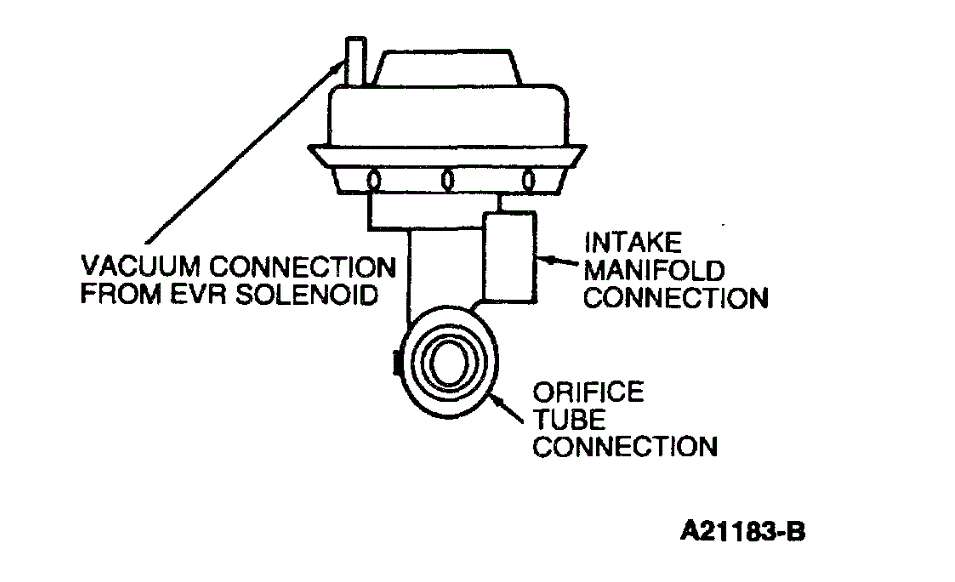
EGR Vacuum Regulator Solenoid
The EGR vacuum regulator solenoid is an electromagnetic device which is used to regulate the vacuum supply to the EGR valve. The solenoid contains a coil which magnetically controls the position of a disc to regulate the vacuum. As the duty cycle to the coil increases, the vacuum signal passed through the solenoid to the EGR valve also increases. Vacuum not directed to the EGR valve is vented through the solenoid vent to atmosphere. Note that at 0% duty cycle (no electrical signal applied), the EGR vacuum regulator solenoid allows some vacuum to pass. but not enough to open the EGR valve.
Exhaust Gas Recirculation Valve
imageOpen In New TabZoom/Print
imageOpen In New TabZoom/Print
Exhaust Gas Recirculation Valve
The EGR valve in the Differential Pressure Feedback EGR system is a conventional, vacuum-actuated EGR valve. The valve increases or decreases the flow of exhaust gas recirculation. As vacuum applied to the EGR valve diaphragm overcomes the spring force, the valve begins to open. As the vacuum signal weakens, at 5.4 kPa (1.6 in-Hg) or less, the spring force closes the valve. The EGR valve is fully open at about 15 kPa (4.5 in-Hg).
Since EGR flow requirement varies greatly, providing service specifications on flow rate is impractical. The on-board diagnostic system monitors the EGR valve function and triggers a Diagnostic Trouble Code if the test criteria is not met. The EGR valve flow rate is not measured directly as part of the field diagnostic procedures.
Orifice Tube Assembly
imageOpen In New TabZoom/Print
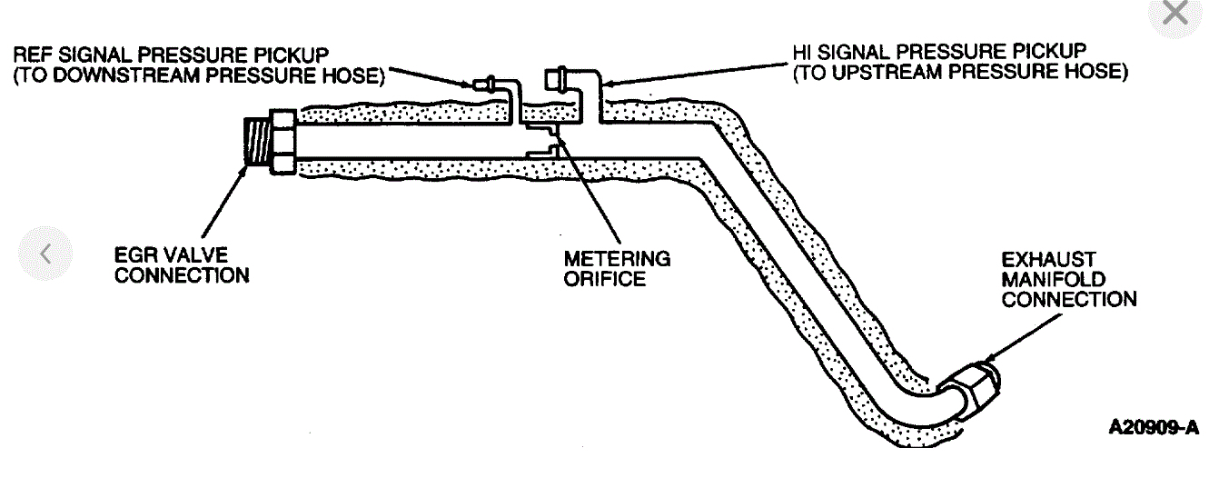
Orifice Tube Assembly
The orifice tube assembly is a section of tubing connecting the exhaust system to the intake manifold. The assembly provides the flow path for the EGR to the intake manifold and also contains the metering orifice and two pressure pickup tubes. The internal metering orifice creates a measurable pressure drop across it as the EGR valve opens and closes. This pressure differential across the orifice is picked up by the differential pressure feedback EGR sensor which provides feedback to the PCM.
Images (Click to make bigger)
Wednesday, July 22nd, 2020 AT 10:36 AM