Welcome back:
I have to be honest, that doesn't even make sense to me. There is a fuel tank pressure sensor, but that isn't related to this issue (EVAP). There is a manifold differential pressure sensor that could be bad, but I really have to question if that is causing this because you get power when you blow into the hose. Ugh!!!
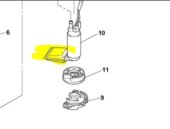
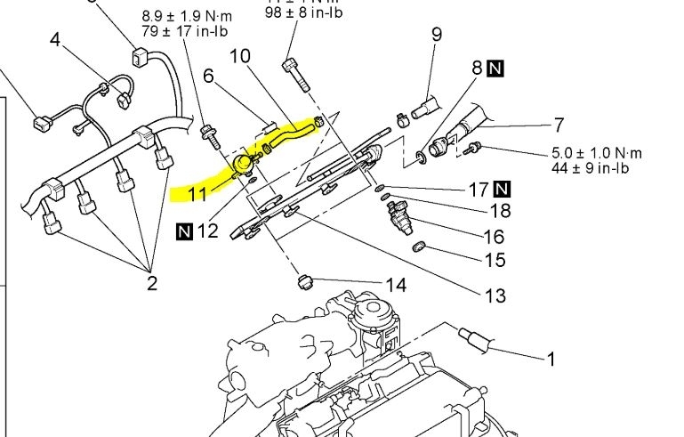
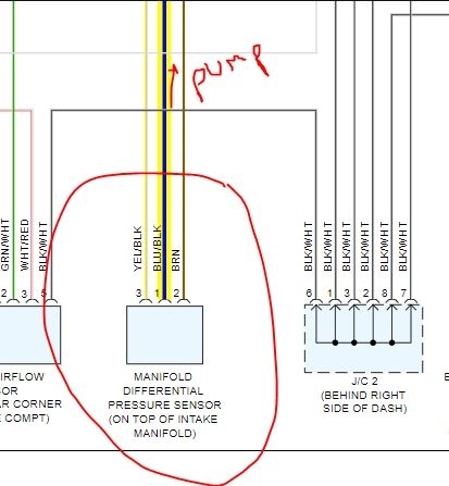
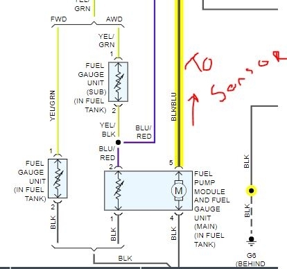
Take a look at the two pics I attached (the first and last pics). One shows the pump and the other the differential pressure sensor. Note that the power to the pump runs through that sensor which then runs to the PCM. That is the only tie in that makes any sense to me. Please understand it's difficult not being there. Also, sorry for the sloppy writing on the pics.
Here are the diagnostics for the sensor I mentioned. All remaining pics correlate with this. I'm adding them if it is something you want to check. However, if this is a problem, you should see a P1400 code. I feel like I am sending you on a wild goose hunt. LOL
___________________________________________
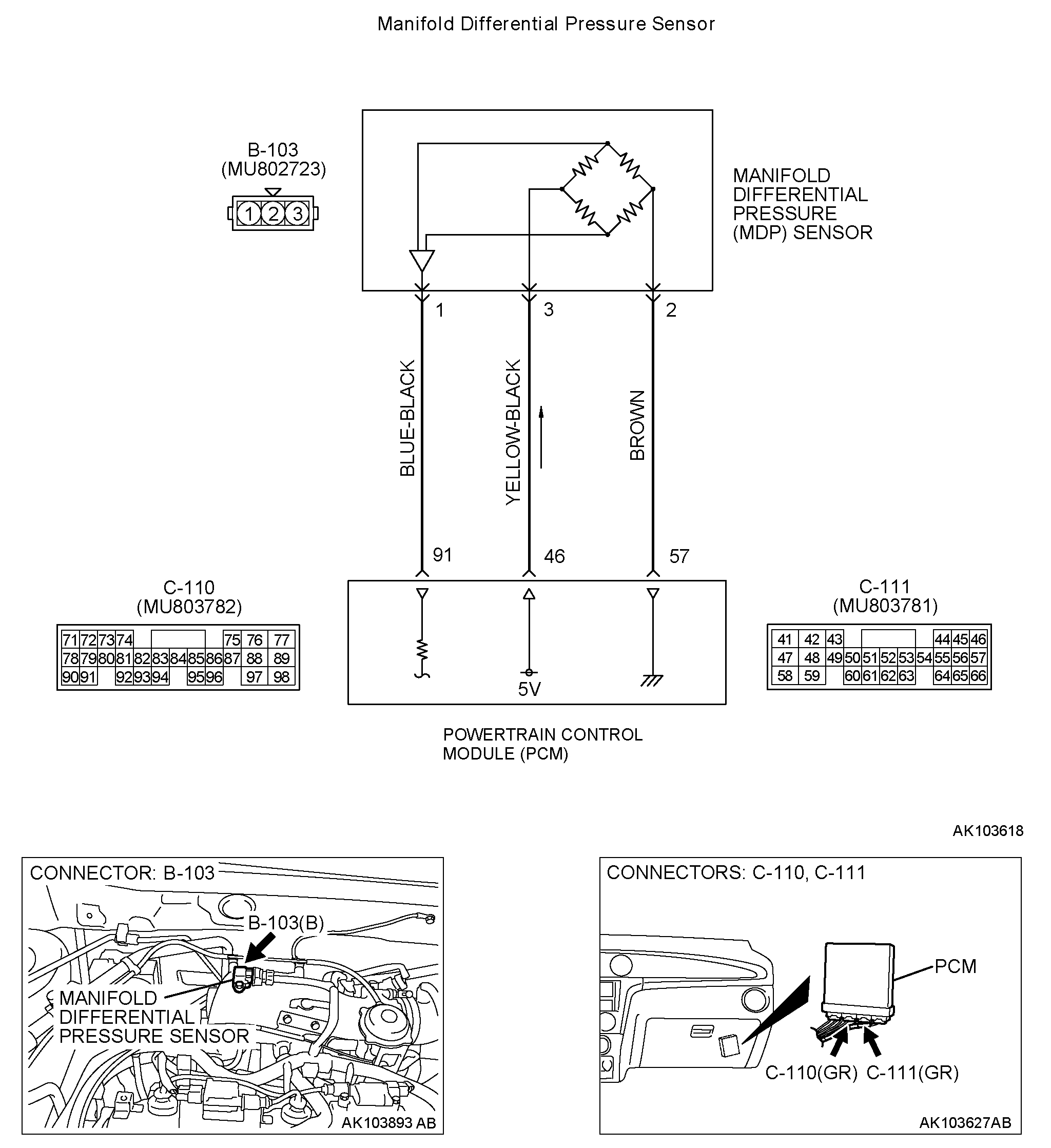
Manifold Differential Pressure Sensor
pic 2
CIRCUIT OPERATION
- A 5-volt voltage is applied on the manifold differential pressure sensor power terminal (terminal No. 3) from the PCM (terminal No. 46). The ground terminal (terminal No. 2) is grounded with the PCM (terminal No. 57).
- A voltage proportional to the pressure in the intake manifold plenum is sent from the manifold differential pressure sensor output terminal (terminal No. 1) to the PCM (terminal No. 91).
TECHNICAL DESCRIPTION
- The manifold differential pressure sensor outputs a voltage which corresponds to the negative pressure in the intake manifold.
- The PCM checks whether the voltage output by manifold differential pressure sensor is within a specified range.
DTC SET CONDITIONS
Check Conditions
- 8 minutes or more have passed after starting the engine. Note that this is only if the engine coolant temperature is less than 0 °C (32 °F) when starting.
- Engine coolant temperature is higher than 45 °C (113 °F).
- Intake air temperature is higher than 0 °C (32 °F).
- Volumetric efficiency is between 30 and 45 percent.
Judgment Criteria
- Manifold differential pressure sensor output voltage has continued to be higher than 4.6 volts [corresponding to an absolute pressure of 118 kPa (17 psi) or higher] for 2 seconds.
or
- Manifold differential pressure sensor output voltage has continued to be lower than 0.1 volt [corresponding to an absolute pressure of 2.4 kPa (0.3 psi) or lower] for 2 seconds.
Check Conditions
- 8 minutes or more have passed after starting the engine. Note that this is only if the engine coolant temperature is 0 °C (32 °F) or more when starting.
- Engine coolant temperature is higher than 45 °C (113 °F).
- Intake air temperature is higher than 0 °C (32 °F).
- Volumetric efficiency is lower than 30 percent.
Judgment Criteria
- Manifold differential pressure sensor output voltage has continued to be higher than 4.2 volts [corresponding to an absolute pressure of 108 kPa (16 psi) or higher] for 2 seconds.
Check Conditions
- 8 minutes or more have passed after starting the engine. Note that this is only if the engine coolant temperature is 0 °C (32 °F) or more when starting.
- Engine coolant temperature is higher than 45 °C (113 °F).
- Intake air temperature is higher than 0 °C (32 °F).
- Volumetric efficiency is higher than 70 percent.
Judgment Criteria
- Manifold differential pressure sensor output voltage has continued to be lower than 1.8 volts [corresponding to an absolute pressure of 46 kPa (4.6 psi) or lower] for 2 seconds.
TROUBLESHOOTING HINTS (The most likely causes for this code to be set are:)
- Manifold differential pressure sensor failed.
- Open or shorted manifold differential pressure sensor circuit, or loose connector.
- PCM failed.
DIAGNOSIS
Required Special Tool:
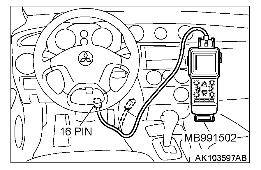
- MB991502: Scan Tool (MUT-II)
STEP 1. Using scan tool MB991502, check data list item 95: Manifold Differential Pressure Sensor.
pic 3
CAUTION: To prevent damage to scan tool MB991502, always turn the ignition switch to the "LOCK" (OFF) position before connecting or disconnecting scan tool MB991502.
1. Connect scan tool MB991502 to the data link connector.
2. Start the engine and run at idle.
3. Set scan tool MB991502 to the data reading mode for item 95, Manifold Differential Pressure Sensor.
- While engine is idling, pressure should be between 64 and 78 kPa (18.9 - 23.0 in.Hg).
4. Turn the ignition switch to the "LOCK" (OFF) position.
Q: Is the sensor operating properly?
YES: It can be assumed that this malfunction is intermittent. Refer to How to Use Troubleshooting/Inspection Service Points.
NO: Go to Step 2.
pic 4
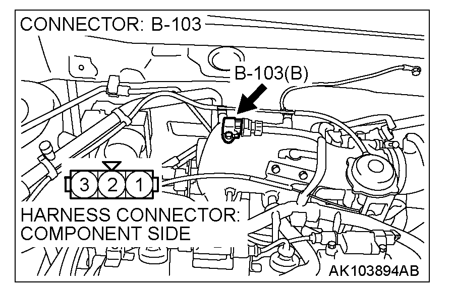
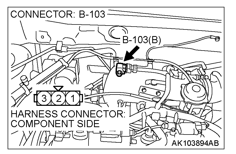
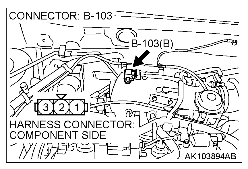
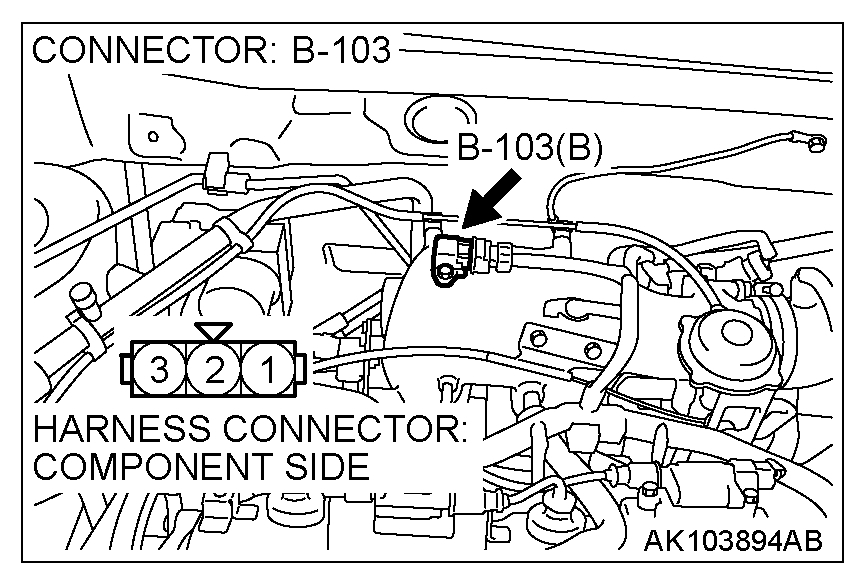
STEP 2. Check connector B-103 at manifold differential pressure sensor for damage.
Q: Is the connector in good condition?
YES: Go to Step 3.
NO: Repair or replace it. Refer to Harness Connector Inspection. Then go to Step 12.
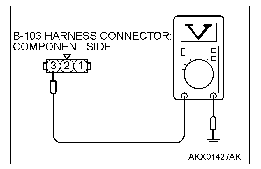
STEP 3. Measure the sensor supply voltage at manifold differential pressure sensor harness side connector B-103.
pic 5
1. Disconnect the connector B-103 and measure at the harness side.
2. Turn the ignition switch to "ON" position.
pic 6
3. Measure the voltage between terminal No. 3 and ground.
- Voltage should measure between 4.8 and 5.2 volts.
4. Turn the ignition switch to "LOCK" (OFF) position.
Q: Is the measured voltage between 4.8 and 5.2 volts?
YES: Go to Step 6.
NO: Go to Step 4.
pic 7
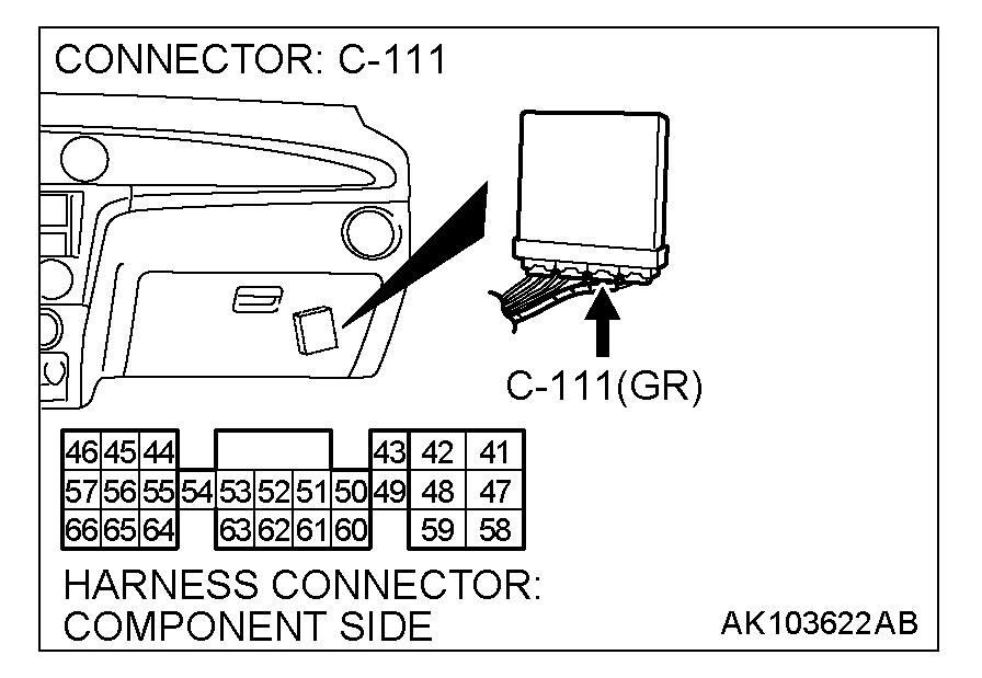
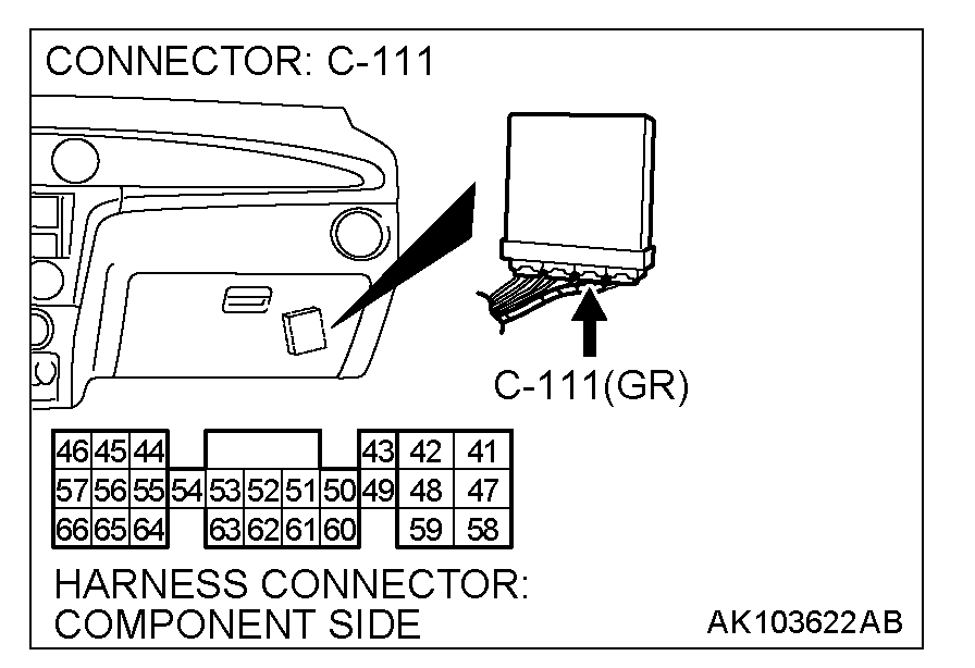
STEP 4. Check connector C-111 at PCM for damage.
Q: Is the connector in good condition?
YES: Go to Step 5.
NO: Repair or replace it. Refer to Harness Connector Inspection. Then go to Step 12.
pic 8
pic 9
STEP 5. Check for open circuit and short circuit to ground between manifold differential pressure sensor connector B-103 (terminal No. 3) and PCM connector C-111 (terminal No. 46).
Q: Is the harness wire in good condition?
YES: Replace the PCM. Then go to Step 12.
NO: Repair it. Then go to Step 12.
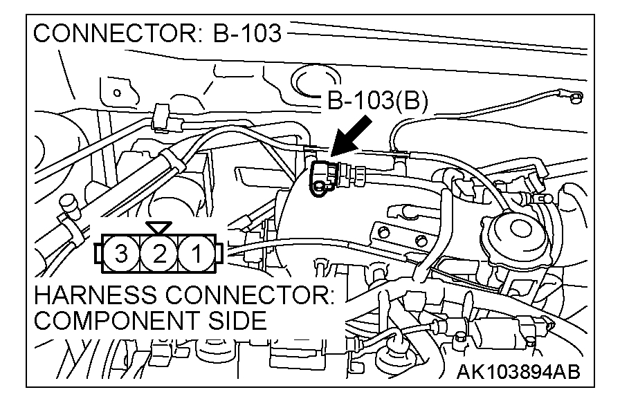
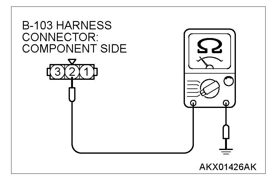
STEP 6. Check for continuity at manifold differential pressure sensor harness side connector B-103.
pic 10
1. Disconnect the connector B-103 and measure at the harness side.
pic 11
2. Measure the continuity between terminal No. 2 and ground.
- Should be less than 2 Ohms.
Q: Does continuity exist?
YES: Go to Step 9.
NO: Go to Step 7.
pic 12
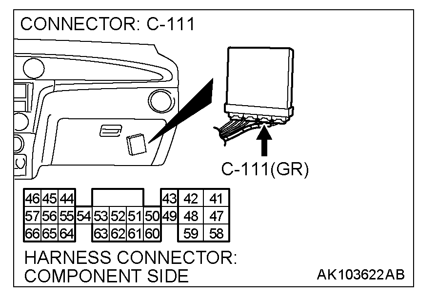
STEP 7. Check connector C-111 at PCM for damage.
Q: Is the connector in good condition?
YES: Go to Step 8.
NO: Repair or replace it. Refer to Harness Connector Inspection. Then go to Step 12.
pic 13
pic 14
STEP 8. Check for open circuit and harness damage between manifold differential pressure sensor connector B-103 (terminal No. 2) and PCM connector C-111 (terminal No. 57).
Q: Is the harness wire in good condition?
YES: Replace the PCM. Then go to Step 12.
NO: Repair it. Then go to Step 12.
pic 15
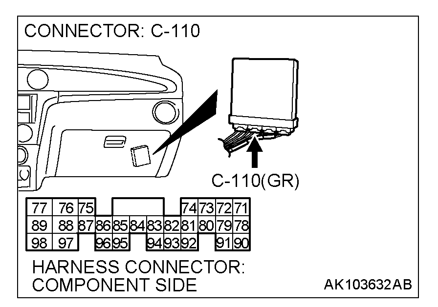
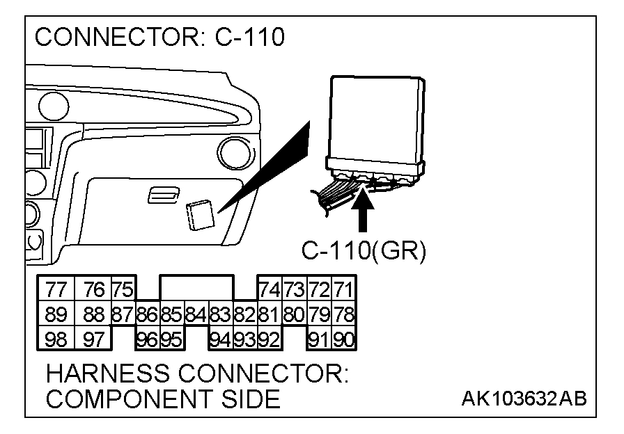
STEP 9. Check connector C-110 at PCM for damage.
Q: Is the connector in good condition?
YES: Go to Step 10.
NO: Repair or replace it. Refer to Harness Connector Inspection. Then go to Step 12.
pic 16
pic 17
STEP 10. Check for harness damage between manifold differential pressure sensor connector B-103 (terminal No. 3) and PCM connector C-111 (terminal No. 46).
Q: Is the harness wire in good condition?
YES: Go to Step 11.
NO: Repair it. Then go to Step 12.
pic 18
pic 19
STEP 11. Check for open circuit and short circuit to ground and harness damage between manifold differential pressure sensor connector B-103 (terminal No. 1) and PCM connector C-110 (terminal No. 91).
Q: Is the harness wire in good condition?
YES: Replace the manifold differential pressure sensor. Then go to Step 12.
NO: Repair it. Then go to Step 12.
STEP 12. Perform the OBD-II drive cycle.
1. Carry out a test drive with the drive cycle pattern. Refer to Trouble Code Diagnosis - OBD-II Drive Cycle - Procedure 6 - Other Monitor.
2. Check the diagnostic trouble code (DTC).
Q: Is DTC P1400 set?
YES: Repeat the troubleshooting.
NO: The procedure is complete.
____________________________
I hope something here makes sense and helps. Let me know. Even with this, it doesn't make sense that the vehicle would get power to the pump after blowing into the fuel line.
Take care,
Joe
Images (Click to enlarge)
Sep 19, 2019 at 7:35 PM