Adding a new flasher relay and now only the turn signal works on the rear driver side?

Tiny
MERKUM901
  • MEMBER
  • 2004 CADILLAC ESCALADE
  • 6.0L
  • V8
  • 4WD
  • AUTOMATIC
  • 216,000 MILES
Hello guys. I added a resistor to my rear driver led turn signal to stop the hyper flash as well as adding a new flasher relay and now only the turn signal works on the rear driver side. No tail, reverse or brake light for the rear driver side. I confirmed my fuse was good so o would love some guidance on where to go from here. I have resistors on all, but the rear passenger turn signal. Help please.
Friday, August 26th, 2022 AT 12:35 PM

4 Replies

Tiny
AL514
  • MECHANIC
  • 4,118 POSTS
Hello, these circuits can be a bit complicated, even on an '04 model. Is this the Escalade EXT or the awd ESV sub-model? And I'm assuming that the passenger side exterior lights are all working, okay?
And where are you adding the resistors? Before the LEDs or on the ground side? This is the Turn Signal Module I'm finding on the wiring diagrams. What relay are you referring to, is this what you replaced?
Was this
answer
helpful?
Yes
No
Friday, August 26th, 2022 AT 3:51 PM
Tiny
AL514
  • MECHANIC
  • 4,118 POSTS
So, what I've added here is the driver side rear turn signal circuit(highlighted) and tail/brake lamps as well. Not knowing how many other LEDS and resistors you have integrated into these circuits, it's difficult to say exactly what is happening. It sounds like you replaced all the bulbs with LEDs and resistors, which is the correct way to do it, except that the circuits are driven by a logic chip. So, if there is a slight difference between the resistors that you added, it might be messing with the logic chip. There are also modules in each front door for controlling the flashers that are on the outside mirrors. (Diagrams 2 and 3). These are all connected to the same power source for the turn signals. I would try putting the old flasher in but leave the resistor where it is for now.

This might be an issue with how much current flow is going through the flasher, It might not be designed to have LEDs and resistors in its circuits. The resistors are only current limiting resistors, and since this is not a standard flasher, there might be a problem with having the LEDs on the turn signal circuit where it is relying on a certain current flow to work. I know they have kits to change over all the lamps in the vehicle, but the Turn signals is definitely an area where this might be more of a headache to do because of the module controller.
Was this
answer
helpful?
Yes
No
Friday, August 26th, 2022 AT 6:13 PM
Tiny
MERKUM901
  • MEMBER
  • 12 POSTS
Thanks for replying. The crazy thing is the turns and hazards working no brake and tail 9n driver side. Also, if what you're saying is correct wouldn't the passenger side be affected too. It is set up the same way.
Was this
answer
helpful?
Yes
No
Sunday, August 28th, 2022 AT 1:03 PM
Tiny
AL514
  • MECHANIC
  • 4,118 POSTS
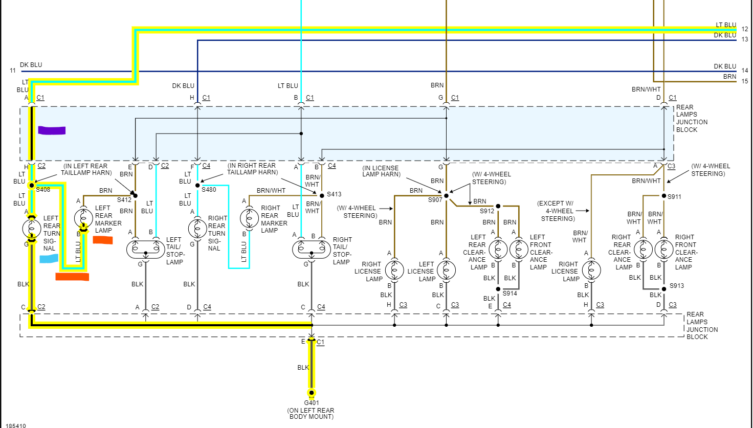
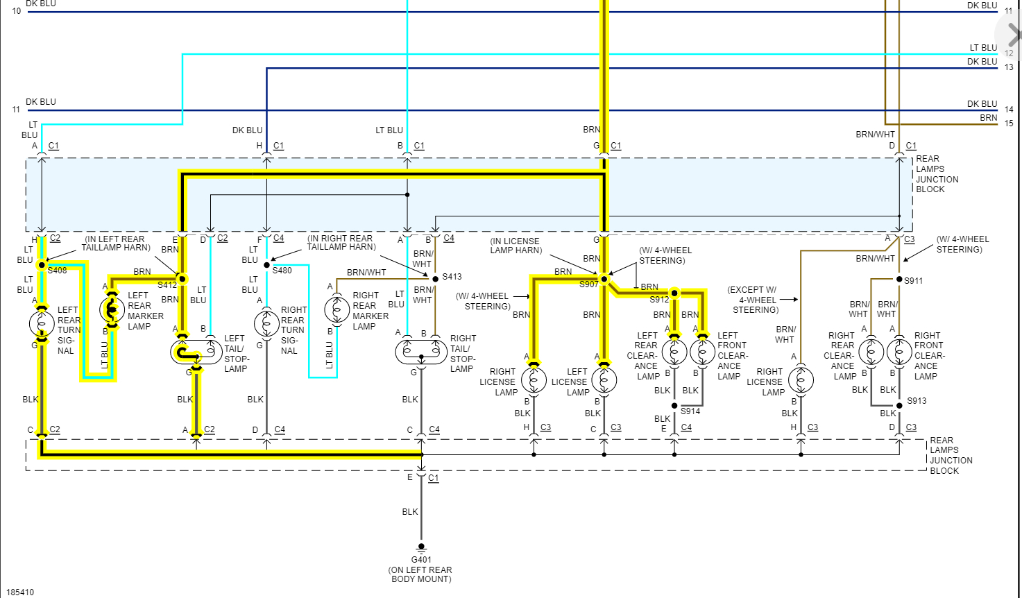
Yeah, I would think so, if you look at this circuit though, they have this rear marker lamp that is a parallel circuit between the turn signal and the taillights. It's underlined in orange in the diagram below. Did you replace that lamp too with a LED? That looks like a circuit where things might get complicated. It makes the marker lamp blink with the turn lamp when the turn signal is on, but then if the taillights are on, no turn signal, the marker light is then in series with the turn signal and in parallel with the taillight bulb that's part of the stop lamp bulb. So that will leave the turn signal, and that marker lamp both slightly dim because they're on the same power feed, its crazy how they designed it. Maybe that marker bulb burned out on the other side and is not affecting the circuit and it's working correctly.
There has to be some slight difference in the 2 setups from drivers to passenger side. I went through this over and over, trying to figure out exactly how the circuits are working, but when it comes to these conversion kits, it's all about current flow. LEDs pull almost no current, hence the resistors.
But maybe trying to unplug a few things, one at a time, and you can find out where the change is. But I do agree with you, if both sides are setup the same, then throwing the logic chips in there, and it can end up being a rabbit hole you go down, and never get out of.
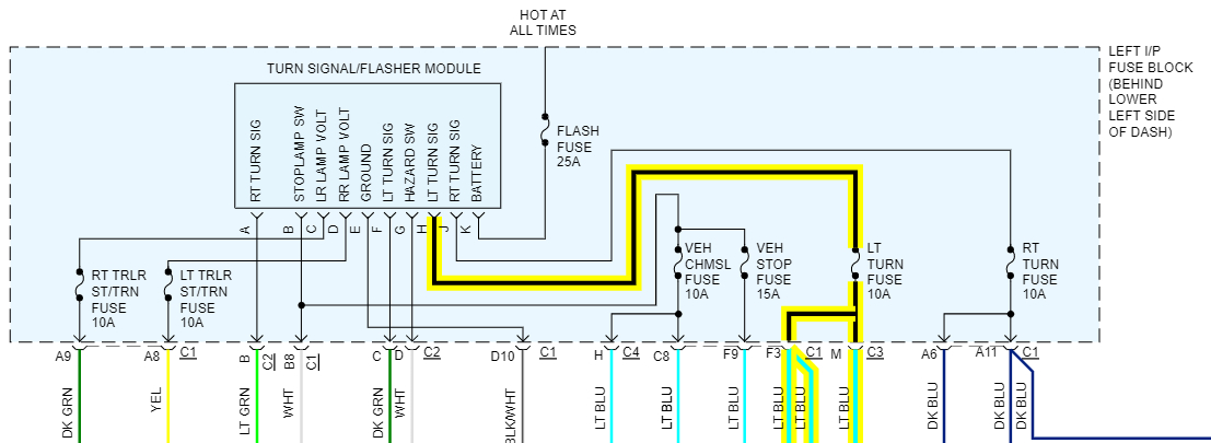
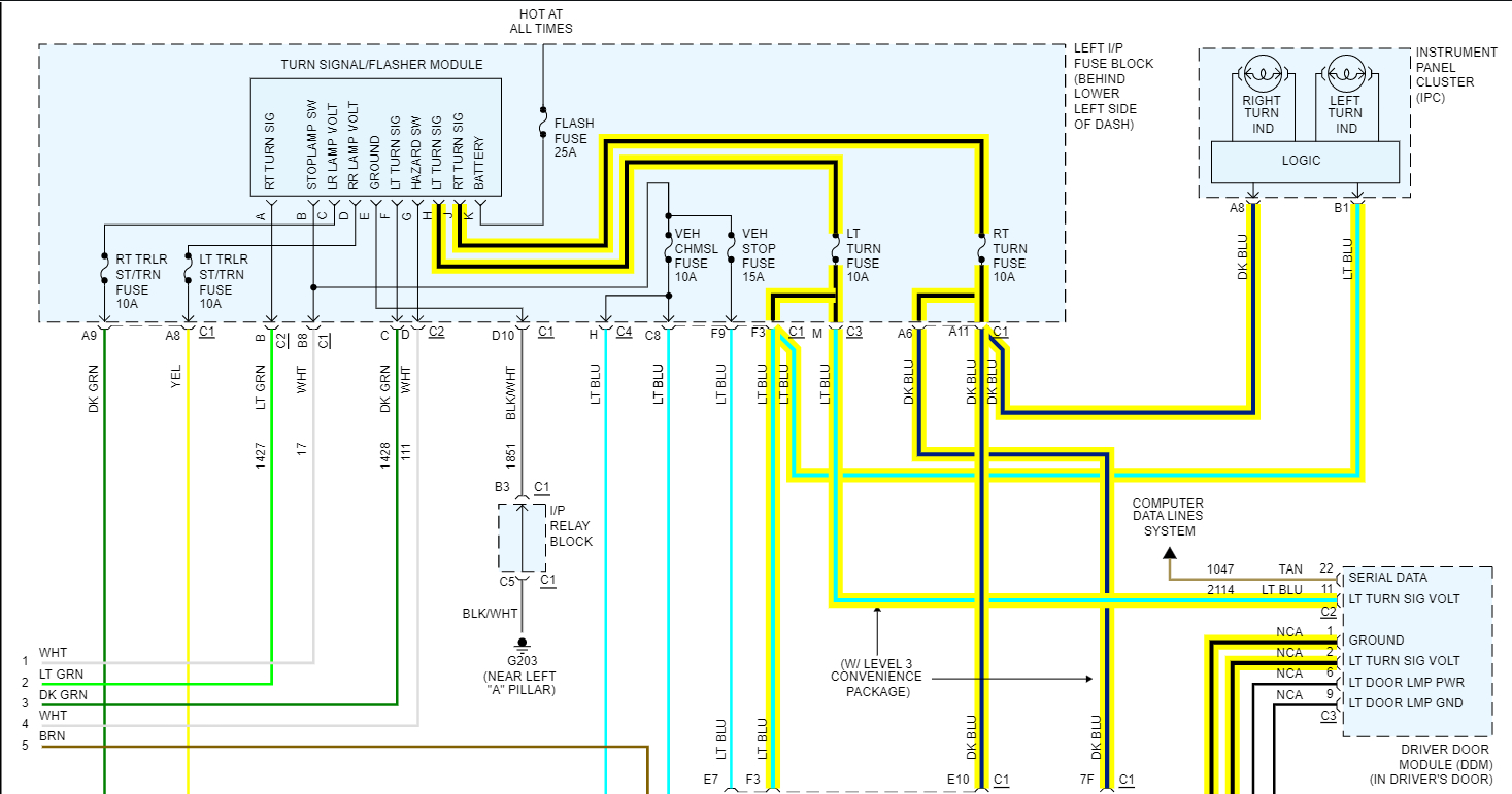
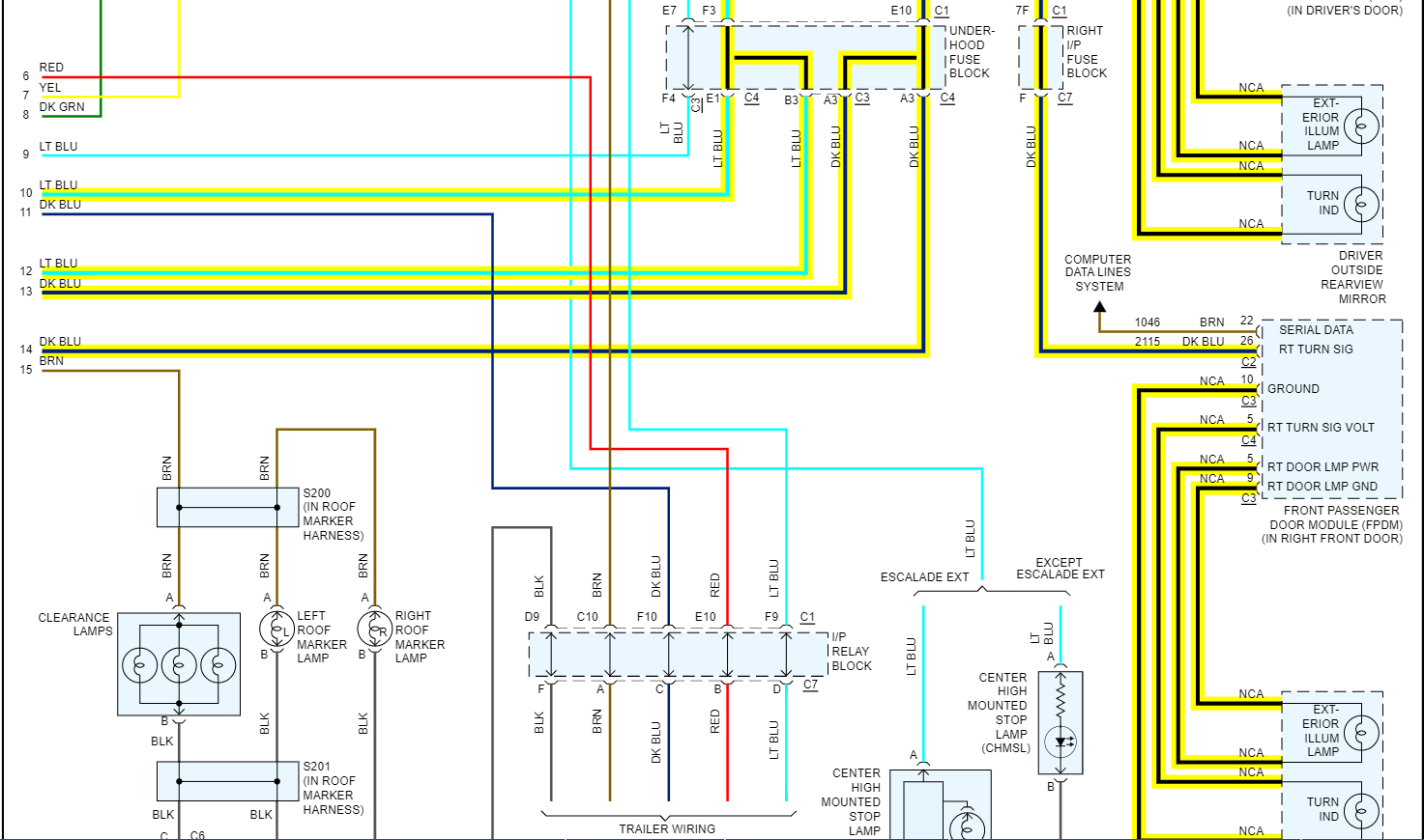
Was this
answer
helpful?
Yes
No
Sunday, August 28th, 2022 AT 1:27 PM

Please login or register to post a reply.

Sponsored links