Hi,
Either of the suggestions can cause the failure, but I honestly feel if the shift fork inserts failed, you would have heard it bang out of gear.
When driving it now, is there anything (other than 5th gear) out of the ordinary? When you shift into 5th, does it feel the same as before?
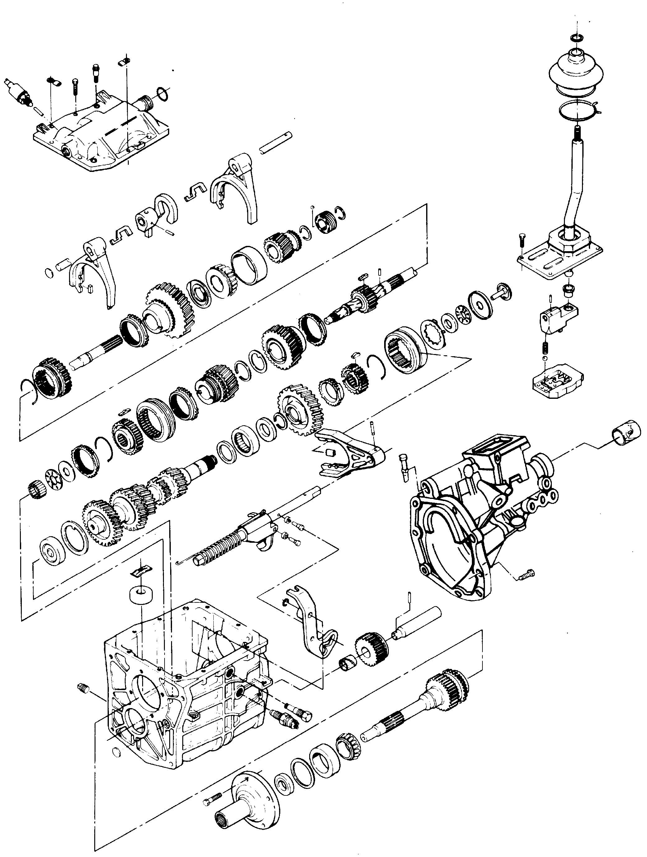
Let me know. By the way, here are the directions for disassembly and assembly. It has to come apart. I suspect a C-clip has failed and fifth can't engage. Also, if the shift fork inserts have come out, you would have lost more than one gear. The attached pics correlate with the directions.
____________________________________________
1985 Chevy Truck S10/T10 P/U 2WD V6-173 2.8L
Warner T-5 (77MM) 5 Speed
Vehicle Transmission and Drivetrain Manual Transmission/Transaxle Service and Repair Procedures Overhaul Disassemble Warner T-5 (77MM) 5 Speed
WARNER T-5 (77MM) 5 SPEED
pic 1
1. Remove drain plug and drain lubricant.
CAUTION: Except for fill plug and gearshift lever attaching bolts, all threaded holes and bolts used in the model T5 transmission case have metric threads. When using replacement bolts be sure they are the same size and length as the originals.
2. Using pin punch and hammer, remove offset lever to shift rail attaching roll pin.
3. Remove adapter housing-to-transmission case bolts, then remove housing and offset lever as assembly.
NOTE: Do not attempt to remove offset lever while adapter housing is still bolted in place. The lever has a positioning lug engaged in the housing detent plate which prevents moving the lever far enough forward for removal.
4. Remove detent ball and spring from offset lever and remove roll pin from adapter housing or offset lever, then remove plastic funnel, thrust bearing race, and thrust bearing from rear of countershaft. (The countershaft rear thrust bearing, washer, and plastic funnel may be found either on the end of countershaft or inside adapter housing.)
5. Remove transmission cover and shift fork assembly attaching bolts, noting location of the two alignment type dowel bolts for assembly reference, and remove cover.
6. Using hammer and punch, remove roll pin from fifth gear shift fork, being sure to place wood block under the fork during removal of roll pin to prevent damage to fifth gear/reverse shift rail.
7. Remove fifth gear synchronizer snap ring, shift fork, fifth gear synchronizer sleeve, blocking ring, and fifth speed drive gear from rear of countershaft.
8. Remove fifth gear insert retainer synchronizer springs and inserts from sleeve and hub, marking position of sleeve and hub for assembly reference.
9. Using tool J-25215 or equivalent, remove snap ring and fifth speed driven gear from rear of output shaft.
10. Using suitable tool, mark. Position of front bearing cap on front of transmission case for assembly reference.
11. Remove front bearing cap bolts and front bearing cap, then remove front race and end play shim(s) from cap and remove oil seal from cap using screwdriver.
12. Turn clutch shaft so that flat surface on main drive gear faces countershaft and remove clutch shaft from transmission case, then remove 15 clutch shaft needle bearings, thrust bearing, and race.
13. Remove output shaft rear bearing race, then tilt output shaft assembly upward and remove assembly from transmission case.
14. Using Suitable tool, unhook over center link spring from rear of transmission case.
15. Remove C-clip attaching reverse lever and fork assembly-to-reverse lever pivot pin.
16. Turn fifth gear-reverse shift rail clockwise (as viewed from top of transmission) to disengage rail from reverse lever assembly, then remove rail from rear of case.
17. Remove fork assembly and reverse lever pivot pin and detach reverse lever from reverse idler gear, then remove reverse lever and fork assembly from transmission case.
18. Remove rear countershaft snap ring and spacer, then, inserting brass drift through clutch shaft opening in front of transmission case and using arbor press, press countershaft assembly rearward to remove rear countershaft bearing. When properly installed, bearing identification numbers face outward.
19. Move countershaft assembly rearward inside case, then tilt upward and remove from case. Remove front countershaft thrust washer from case, noting washer position for assembly reference.
20. Remove countershaft rear bearing spacer, then remove roll pin from forward end of reverse idler shaft using hammer and punch.
21. Remove reverse idler shaft and gear from transmission case, noting gear position for assembly reference.
22. Using arbor press, remove countershaft front bearing from transmission case.
23. Using tool J-29721 and J-22912-01 or equivalent, remove clutch shaft front bearing.
24. Using suitable tool, remove rear adapter housing seal.
___________________________________________________________________
1985 Chevy Truck S10/T10 P/U 2WD V6-173 2.8L
Warner T-5 (77MM) 5 Speed
Vehicle Transmission and Drivetrain Manual Transmission/Transaxle Service and Repair Procedures Overhaul Assemble Warner T-5 (77MM) 5 Speed
WARNER T-5 (77MM) 5 SPEED
pic 2
1. Coat countershaft front bearing, Fig 1 with suitable sealant and, using arbor press, install countershaft front bearing flush with case.
2. Lubricate countershaft tabbed thrust washer and install so tab engages proper depression in case.
3. Tip transmission case on end and install countershaft in front of bearing bore, then install countershaft rear bearing spacer.
4. Lubricate rear bearing and, using tool J-29895 and J-33032 or equivalent, install bearing so that it extends 0.125 in. (3 mm.) Beyond case surface. Proper tool must be used to prevent needles from catching on countershaft shoulder.
5. Position reverse idler gear in case with shift lever groove facing rear of case and install reverse idler shaft from rear of case. Install retaining roll pin in shaft.
6. Install output shaft assembly in case.
7. Using tool J-2995 or equivalent and arbor press, install front clutch shaft bearing on clutch shaft, then lubricate pilot roller bearings and install in clutch shaft.
8. Install thrust bearing and race in clutch shaft, then install rear output shaft bearing race cap.
9. Install fourth gear blocking ring on output shaft, then install clutch shaft in case and engage in third-fourth synchronizer sleeve and blocking ring.
10. Using tool J-26625 or equivalent, install new oil seal in front bearing cap.
11. Install front bearing race in cap and temporarily install front bearing cap.
12. Coat pivot bolt threads with sealer, then install fifth speed-reverse lever, pivot bolt, and retaining C-clip. Engage reverse lever fork in reverse idler gear.
13. Install fifth speed driven gear and retaining snap ring on rear of output shaft, then install countershaft rear bearing spacer and retaining snap ring.
14. Install fifth speed gear on countershaft, then insert fifth speed-reverse rail through opening in rear of case and install in reverse fifth speed lever, turning rail during installation to facilitate engagement with lever.
15. Install fifth speed-reverse lever over center spring, then assemble fifth gear synchronizer sleeve, insert springs, and insert retainer using assembly reference marks.
16. Install plastic inserts in notches on either side of fifth speed shift fork, then put assembled fifth gear synchronizer sleeve on fifth speed shift fork and slide onto countershaft and fifth speed-reverse rail, making sure roll pin holes in fifth-reverse rail and fifth speed shift fork are aligned.
17. Placing assembled fifth speed reverse rail and shift fork on block of wood, install retaining roll pin, then install thrust race against fifth speed synchronizer hub and install retaining snap ring.
18. Lubricate needle type thrust bearing and thrust race and install bearing against race on countershaft.
19. Install thrust race over thrust bearing and insert plastic funnel into hole in end of countershaft gear.
20. Install adapter housing temporarily without sealing or torquing bolts, then turn transmission case on end and mount dial indicator on adapter housing with stylus on end of output shaft.
21. Turn clutch and output shaft to zero dial indicator, then pull upward on output shaft until end play is eliminated. To completely eliminate end play, bearings must be preloaded from 0. OO1-0.O05 in. (0.03-0.13 mm.).
22. Select shim pack measuring 0.001-.005 in. Thicker than measured end play and, placing transmission horizontally on workbench, remove front bearing cap and race, then add shim to bearing cap and install clutch shaft bearing race cap.
23. Apply suitable sealant on case mating surface of front bearing cap, then align assembly reference marks and install front bearing cap, torquing retaining bolts to 15 ft. Lbs.
24. Recheck end play to make sure there is no end play.
25. Remove adapter housing and, using tool J-29184 or equivalent, install adapter housing rear seal.
26. Move shift forks on transmission cover and synchronizer rings inside transmission to the neutral position.
27. Apply suitable sealant to cover mating surface of transmission and lower cover assembly onto case, aligning shift forks and synchronizer sleeves, then center cover on case to engage reverse relay lever and install dowel bolts in cover.
28. Install remaining bolts and torque all cover bolts to 9 ft. Lbs.
NOTE: The offset lever-to-shift rail roll pin hole should be in a vertical position after completion of steps 26 through 28.
29. Apply suitable sealant to adapter housing-to-transmission case mating surface and install adapter housing over output shaft and shift rail so that shift rail just enters shift cover opening.
30. Install detent spring into offset lever and place ball in neutral guide plate detent. Applying pressure on ball with detent spring and offset lever, slide offset lever on shift rail and seat adapter housing against transmission case so that the offset lever and shift rail roll pin holes are aligned and in a vertical position.
31. Install and torque adapter housing retaining bolts to 25 ft. Lbs.
32. Install roll pin in offset lever and shift rail, then install damper sleeve in offset lever.
33. Coat backup lamp switch threads with suitable sealant and install switch in case.
Let me know.
Joe
Images (Click to make bigger)
Thursday, May 28th, 2020 AT 7:59 PM