Thank you for the compliments and sorry it took so long for this reply. I am not sure if your scanner has the capabilities so we shall start with the following trouble shooting list.
CRUISE CONTROL WON'T SET SPEED (INDICATOR LIGHT FLASHES)
Perform FAIL-SAFE SYSTEM CHECK ,
BRAKE &/OR CLUTCH CANCEL SWITCH CHECK ,
STEERING SWITCH CHECK ,
VEHICLE SPEED SENSOR CHECK
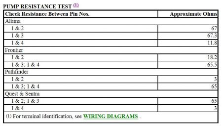
PUMP CIRCUIT CHECK .
FAIL-SAFE SYSTEM CHECK
1. When ASCD control unit senses a fault, cruise control operation is deactivated. CRUISE indicator light will flash until fault is no longer apparent. The following conditions can cause fail -safe system to operate:
Steering switch stuck.
ASCD pump motor power or ground circuit open or shorted.
Air valve power or ground circuit open or shorted.
Release valve power or ground circuit open or shorted.
Vehicle speed sensor faulty.
ASCD control unit internal malfunction.
Brake cancel switch or stoplight switch faulty.
2. Turn ignition on. Turn cruise control main switch to ON position. If CRUISE indicator light does not flash, go to next step. If CRUISE indicator light flashes, perform STEERING SWITCH CHECK .
3. Drive vehicle at a speed greater than 30 MPH. Turn cruise control main switch to ON position. Press SET/COAST switch. If CRUISE indicator light does not flash, go to next step. If CRUISE indicator light flashes, perform VEHICLE SPEED SENSOR CHECK and PUMP CIRCUIT CHECK . If no faults are found and CRUISE indicator light still flashes, replace ASCD control unit.
4. While driving vehicle with cruise control main switch in ON position, slowly depress brake pedal for at least 5 seconds. If CRUISE indicator light does not flash, cruise control system is okay at this time. If CRUISE indicator light flashes, perform BRAKE &/OR CLUTCH CANCEL SWITCH CHECK .
STEERING SWITCH CHECK
1. Turn ignition off. Disconnect ASCD control unit harness connector. Using DVOM, measure voltage between specified terminals at ASCD control unit harness connector while pressing each switch. See STEERING SWITCH CIRCUIT TEST table.
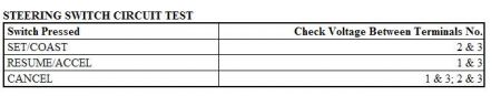

DVOM should indicate battery voltage with switch pressed, and zero volts with switch released. If voltage is as specified, steering switch is okay. If voltage is not as specified, go to next step.
2. Attempt to sound horn. If horn sounds, go to next step. If horn does not sound, check fuses. Replace if necessary. If fuses are okay, check horn relay. Check for open or short in wiring harness between horn and fuse. Repair as necessary.
3. Check steering switch. Replace if necessary. If steering switch is okay, check for open or short in wiring harness between steering switch and ASCD control unit. Repair as necessary.
STEERING SWITCH
1. Remove steering switch assembly from steering wheel. Using DVOM, check for continuity between switch terminals No. 2 and 3 while pressing SET/COAST switch. Reverse test leads and repeat continuity check. Continuity should be present in both directions.
2. Check for continuity between switch terminals No. 1 and 3 while pressing RESUME/ACCEL switch. Reverse test leads and repeat continuity check. Continuity should be present in both directions.
3. Check for continuity between switch terminals No. 2 and 3 while pressing CANCEL switch. Reverse test leads and repeat continuity check. Continuity should be present in only one direction.
4. Check for continuity between switch terminals No. 1 and 3 while pressing CANCEL switch. Reverse test leads and repeat continuity check. Continuity should be present in only one direction. Replace steering switch assembly if continuity is not as specified for all continuity checks.
BRAKE &/OR CLUTCH CANCEL SWITCH CHECK
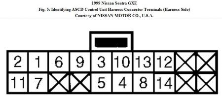
1. Turn ignition off. Disconnect ASCD control unit harness connector. Turn ignition on. Turn cruise control main switch to ON position. Place gearshift lever in any position except "P" or "N" (A/T). DO NOT depress clutch or brake pedal. Using DVOM, measure voltage between ground and terminal No. 5 at ASCD control unit harness connector. See Fig. 5 . DVOM should indicate battery voltage. Depress brake or clutch pedal, or place gearshift lever in "P" or "N" position (A/T). DVOM should indicate zero volts. If voltage is as specified, go to next step. If voltage is not as specified, check the following.
Check brake cancel switch. See BRAKE CANCEL SWITCH under COMPONENT TESTS.
Check clutch cancel switch (if equipped). See CLUTCH CANCEL SWITCH (M/T MODELS) under COMPONENT TESTS.
Check inhibitor switch. See INHIBITOR SWITCH (A/T MODELS) under COMPONENT TESTS.
Check ASCD hold relay. See RELAYS under COMPONENT TESTS.
Check inhibitor relay. See RELAYS under COMPONENT TESTS.
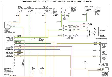
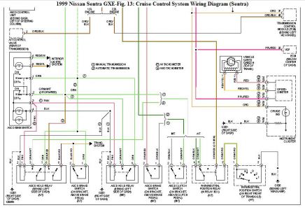
Check related wiring harness for opens or shorts. See WIRING DIAGRAMS .
2. Using DVOM, measure voltage between ground and terminal No. 11 at ASCD control unit harness connector. See WIRING DIAGRAMS . DVOM should indicate battery voltage with brake pedal depressed, and zero voltage with brake pedal released. If voltage is as specified, brake and clutch cancel switches and circuit are okay. If voltage is not as specified, go to next step.
3. Check fuses. Replace if necessary. If fuses are okay, check for open or short in wiring harness between ASCD control unit and stoplight switch. See WIRING DIAGRAMS . Repair as necessary. If circuit is okay, check stoplight switch. See STOPLIGHT SWITCH under COMPONENT TESTS. Replace as necessary.
COMPONENT TESTS
BRAKE CANCEL SWITCH
Disconnect 2-pin brake cancel switch harness connector. Using DVOM, check for continuity between switch terminals. Ensure continuity is present only when brake pedal is released. Replace brake cancel switch if continuity is not as specified.
CLUTCH CANCEL SWITCH (M/T MODELS)
Disconnect 2-pin clutch cancel switch harness connector. Using DVOM, check for continuity between switch terminals. Ensure continuity is present only when clutch pedal is released. Replace clutch cancel switch if continuity is not as specified.
INHIBITOR SWITCH (A/T MODELS)
Disconnect inhibitor switch harness connector (located on transmission/transaxle). Using DVOM, check for continuity between terminals No. 1 and 2 of inhibitor switch while moving gearshift lever through all gear positions. Ensure continuity is present in Park and Neutral only. Replace inhibitor switch if continuity is not as specified.
RELAYS ASCD Hold Relay (4-Pin)
1. Remove relay. Using DVOM, ensure continuity is present between relay terminals No. 1 and 2. See Fig. 1 . Replace relay if continuity is not present. If continuity is present, go to next step.
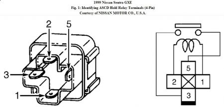
2. Ensure continuity is not present between relay terminals No. 3 and 5. Replace relay if continuity is present. If continuity is not present, go to next step.
3. Energize relay by connecting 12-volt source across relay terminals No. 1 and 2. With relay energized, ensure continuity is present between relay terminals No. 3 and 5. Replace relay if continuity is not as specified.
ASCD Hold Relay (6-Pin)
1. Remove relay. Using DVOM, ensure continuity is present between relay terminals No. 1 and 2. See Fig. 2 . Replace relay if continuity is not present. If continuity is present, go to next step.
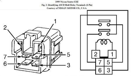
2. Ensure continuity is not present between relay terminals No. 3 and 5, and between terminals No. 6 and 7. Replace relay if continuity is present. If continuity is not present, go to next step.
3. Energize relay by connecting 12-volt source across relay terminals No. 1 and 2. With relay energized, ensure continuity is present between relay terminals No. 3 and 5, and between terminals No. 6 and 7. Replace relay if continuity is not as specified.
We shalll start with this. If there is anything else that you require, let me know.
Aug 7, 2009 at 8:32 AM