Hi COMERCIALAUTOSERVICE,
Thank you for the donation.
Here are the description of the various codes.
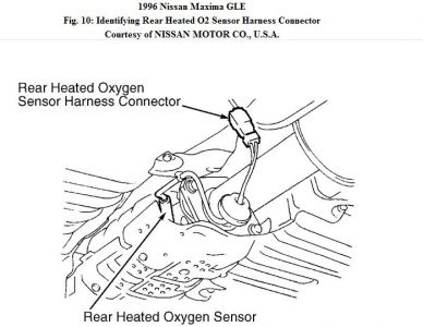
DTC P0136 - REAR HEATED OXYGEN (O2) SENSOR HEATER
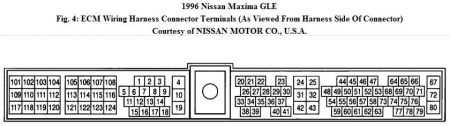
Check Ground Circuit - Turn ignition switch to OFF position. Disconnect rear heated O2 sensor and ECM harness connectors. Using an ohmmeter, check continuity between rear heated O2 sensor harness connector terminal No. 1 and ECM harness connector terminal No. 105 (Purple wire). If no continuity exists, repair open in Purple wire. If continuity exists, check continuity between ECM harness connector terminal No. 112 (Black wire) and ground. If no continuity exists, repair open in Black wire. If continuity exists, go to next step.
2. Check Power Supply - Turn ignition switch to ON position. Using a voltmeter, measure voltage between rear heated O2 sensor harness connector terminal No. 3 (Red/Black wire) and ground. If battery voltage does not exist, repair fault in Red/Black wire as required. If battery voltage exists, go to next step.
3. Check Input Signal Circuit - Turn ignition switch to OFF position. Using an ohmmeter, check continuity between ECM harness connector terminal No. 56 and rear heated O2 sensor harness connector terminal No. 2 (White wire). If no continuity exists, repair open in White wire. If continuity exists, check continuity between ECM harness connector terminal No. 56 (White wire) and ground. If continuity exists, repair short in White wire. If no continuity exists, go to next step.
4. Check Component - Inspect rear heated O2 sensor. Replace rear heated O2 sensor as required. Disconnect and reconnect harness connectors in circuit and perform FINAL CHECK.
DTC P0440 - EVAPORATIVE EMISSION (EVAP) CONTROL SYSTEM
1. Check Fuel Filler Cap - Verify fuel filler cap does not remain open, closes properly and does not contain any foreign matter. Verify fuel filler cap is original equipment. Check fuel tank vacuum relief valve. Wipe valve housing clean. Suck air through cap. There should be a slight resistance accompanied by valve clicks indicating valve "A" is okay. Blow air on fuel tank side of cap. Air should pass freely through valve "B". If valve is clogged or no resistance is felt replace cap assembly. If cap tests okay, go to next step.
2. Check EVAP Canister Purge Volume Control Valve - Disconnect EVAP canister purge volume control valve harness connector. Using an ohmmeter, measure resistance between EVAP canister purge volume control valve harness connector terminals as specified.
Resistance should be 30 ohms:
"� EVAP canister purge volume control valve harness connector terminals No. 2 and 1.
"� EVAP canister purge volume control valve harness connector terminals No. 2 and 3.
"� EVAP canister purge volume control valve harness connector terminals No. 5 and 4.
"� EVAP canister purge volume control valve harness connector terminals No. 5 and 6.
If resistance measured is not as specified, replace valve. If resistance is as specified, go to next step.
3. Reconnect valve harness connector. Remove valve from intake manifold collector and disconnect hoses. Plug purge hose. Turn ignition switch to ON and to OFF. Check that valve shaft moves forward and backward according to ignition switch position. If valve shaft does not move as specified, replace valve. If valve shaft is okay, go to next step.
4. Check EVAP Canister Purge Control Valve - Blow air in ports "A", "B" and "C" of EVAP canister purge control valve. Verify there is no leakage. Apply 3.94 - 5.91 in. Hg vacuum to port "A". Blow air in port "C" and verify it flows freely through port "B". If EVAP canister purge control valve does not function as specified, replace valve. If valve is okay, go to next step.
5. Check EVAP Canister Vent Control Valve - Disconnect EVAP canister vent control valve harness connector. Connect battery positive to valve terminal No. 1 and battery negative to valve terminal No. 2. Verify there is no air passage continuity from "A" to "B". Disconnect battery, verify there is air passage continuity from "A" to "B". If valve does not function as specified, replace valve. If valve functions as specified, go to next step.
6. Check EVAP Canister Purge Control Solenoid Valve - Inspect EVAP canister purge control solenoid valve. See the SYSTEM/COMPONENT TESTS article. If EVAP canister purge control solenoid valve does not function as specified, replace valve. If EVAP canister purge control solenoid valve functions properly, go to next step.
7. Check Components - Check AP sensor. See DTC P0105. - ABSOLUTE PRESSURE (AP) SENSOR. If sensor fails test, replace sensor. If sensor tests okay, check MAP/BARO switch solenoid valve. See DTC P1105 - MANIFOLD ABSOLUTE PRESSURE (MAP)/BAROMETRIC PRESSURE (BARO) SWITCH SOLENOID VALVE. If valve fails test, replace valve. If valve tests okay, check TFT sensor. See DTC P0180 - TANK FUEL TEMPERATURE (TFT) SENSOR. If sensor fails test, replace sensor. If sensor tests okay, go to next step.
8. Check EVAP Purge Line - Check EVAP purge line for cracks. Apply soapy water to locations in question and apply pump pressure. Do not allow pump pressure to exceed 1.93 PSI. Look for air bubbles. Turn ignition switch to OFF position. Apply 12 volts to EVAP canister vent control valve. Apply 12 volts to vacuum cut valve bypass valve. Disconnect rubber tube between vacuum cut valve and EVAP shut valve. Set up one way valve pressure gauge and pump. Clean EVAP purge line using air blower and go to next step.
9. Inspect EVAP system components. Replace EVAP components as required. Disconnect and reconnect harness connectors in circuit and perform FINAL CHECK.
DTC P0446 - EVAPORATIVE EMISSION (EVAP) CANISTER VENT CONTROL VALVE
1, Check Power Supply - Turn ignition switch to OFF position. Disconnect EVAP canister vent control valve harness connector. Turn ignition switch to ON position. Using a voltmeter, measure voltage between EVAP canister vent control valve harness connector terminal No. 2 (Black/White wire) and ground. If battery voltage does not exist, check for blown fuse No. 9 or fault in Black/White wire. Repair or replace as required.
2. Check Output Signal Circuit - Turn ignition switch to OFF position. Disconnect ECM harness connector. Check harness continuity between EVAP canister vent control valve harness connector terminal No. 1 and ECM harness connector terminal No. 108 (Red wire). If no continuity exists, repair open in Red wire. If continuity exists, go to next step.
3. Check Component - Check rubber tube to EVAP canister vent control valve for obstructions. Clear or clean tube as required. Check EVAP canister vent control valve and EVAP control system pressure sensor. Replace EVAP components as required. Disconnect and reconnect harness connectors in circuit and perform FINAL CHECK.
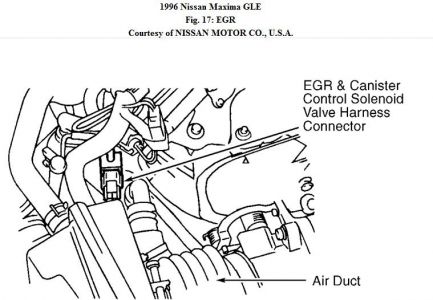
DTC P1400 - EGRC SOLENOID VALVE
1. Check Power Supply - Turn ignition switch to OFF position. Disconnect EGRC solenoid valve harness connector. Turn ignition switch to ON position. Using a voltmeter, measure voltage between EGRC solenoid valve harness connector terminal No. 2 (Red/Yellow wire) and ground. If battery voltage does not exist, check for blown fuse No. 17 or fault in Red/Yellow wire. Replace or repair as required. If battery voltage exists, go to next step.
2. Check Output Signal Circuit - Turn ignition switch to OFF position. Disconnect ECM harness connector. Using an ohmmeter, check continuity between EGRC solenoid valve harness connector terminal No. 1 and ECM harness connector terminal No. 103 (Blue/Black wire). If no continuity exists, repair open in Blue/Black wire. If continuity exists, go to next step.
3. Check Component - Inspect EGRC solenoid valve. Replace EGRC solenoid valve as required. Disconnect and reconnect harness connectors in circuit and perform FINAL CHECK.
Tuesday, December 1st, 2009 AT 3:05 PM