Hi guys. Maybe I can clear up some of the confusion. Fuse link wires are just a piece of wire. There's nothing inside them like fuses or lumps. The wire is a standard copper wire, but it is of a smaller diameter than the rest of the wires it protects. That makes it the weak link in the chain, so it is what burns open. For legal and safety ramifications, that link can not be replaced with any old piece of wire of the same gauge. Unlike regular wire, the insulation on fuse link wires will not burn or melt. It will be a dull color, ... Much different-looking than normal, shiny wire. The color denotes its current rating. You can buy replacement fuse link wire at any auto parts store. Typically you'll get about 12" which is plenty to make two or three repairs. The length of the section you splice in is not important.
To test a fuse link wire, just tug on it. If it acts like a wire, it's good. If it's burned open, it will stretch like a rubber band. Since these are always under the hood where moisture is an issue, always solder the splices, then seal them with heat-shrink tubing with hot-melt glue inside. Never use electrical tape in a car or truck. It will unravel into a gooey mess on a hot day.
A fuse link wire should not be replaced with a fuse holder and fuse, even of the correct current rating. Some people do that when there's an intermittent short that is hard to locate. The problem is the wire takes some time to burn open and it can hold up to a momentary overload such as when a motor draws high start-up current. A regular fuse used for a radiator fan motor, for example, would pop as soon as the motor turned on, but the delayed action of a fuse link wire would prevent it from burning open.
One problem with fuse link wires, when you're diagnosing a dead circuit, is when the wire burns open, it leaves a carbon track behind, similar to what is found inside a distributor cap that got wet. That carbon can conduct enough current that a digital voltmeter can "see" the 12 volts coming from the battery. You can't get enough current through that carbon, so the circuit is dead, but the voltmeter incorrectly says everything is okay up to that point. This is where an inexpensive test light is much more accurate than the voltmeter. Voltmeters work by detecting voltage. That's easy to do. Test lights work by current running through the bulb to make it glow. That can only occur in a circuit that is really okay.
As for the charging system, in my opinion, this is the best system ever produced. Unlike GM which is famous for innovations that benefit GM, Chrysler has a real long history of innovations that benefit car owners. This wondrous story is about two of them. Chrysler developed the "AC generator" for use on 1960 models, and copyrighted the term, "alternator". It develops alternating current, just like we have in our homes, but it's three-phase, like is found in factories, because it is much more efficient. There is no way to store alternating current, so six "diodes", (one-way valves for electrical current flow), redirect the various currents to all go one way out the output terminal, to the battery's positive post.
Three things are always needed to generate a current mechanically, meaning a generator. Those are a wire, a magnetic field, and most importantly, movement between them. That's why we need to spin it with a drive belt. The wire is wound up into coils so the voltage will be "induced" into all of them. That increases the voltage generated to around 14 volts. The magnet is an electromagnet, and is also a coil of wire. Up to three amps maximum is all that's needed to make the magnetic field. That is passed through a pair of brushes to the rotating coil. In the older DC generators, the high output current was taken off the rotating armature. On a good day, that could be as high as 30 amps, (pretty pathetic by today's standards), and all that current had to go through the brushes. That was a lot to ask of those sad brushes.
Once the battery has been recharged from cranking the engine, the only current needed from the alternator is enough to run the rest of the electrical system. It is not practical to slow the drive belt to reduce alternator output, and we can't remove some of the loops of wire from the "stator", or output winding, but it is real easy to reduce the strength of the magnetic field to make it less efficient. This is where the voltage regulator comes in. It is a variable resistance in series with the field winding. "Series" means whatever current flows through the coil goes through the regulator next, just like water flowing in a river flows through one town, then the next town. By increasing its resistance, less current flows through the regulator / field winding, that makes a weaker magnetic field, and that induces less voltage, (electrical pressure) in the stator winding. Less voltage causes less current to flow out of the output terminal.
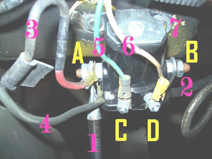
The first version of Chrysler's charging system was used from 1960 to 1969. It has nothing to do with whether the vehicle had breaker point ignition or electronic ignition. You won't be tested on this later, but this first version was called a "B"-type circuit because the voltage regulator came "Before" the field winding. To say that more clearly, current flow started, for purposes of this story, at the battery's positive post, flowed through the ignition switch, then to a number of places under the hood. Everything under the hood that got 12 volts from the ignition switch used dark blue wires on almost all cars, and red wires on the majority of trucks. That included the ignition system, electric automatic choke heater, and things like that. That 12 volts went to the voltage regulator first. This was used to power the regulator and it was the current supply for the alternator's field winding. It was also where the regulator sensed system voltage so it knew what to do to control alternator output. It had to sense system voltage in relation to something, meaning ground, so the regulator has to be bolted to a good, paint-free place on the body sheet metal.
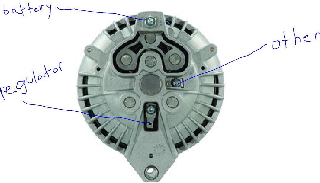
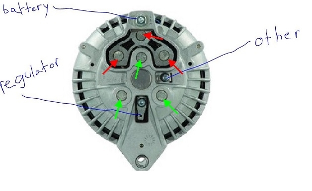
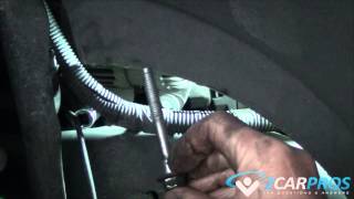
The current continued on to the field terminal on the back of the alternator. From there is flowed through the first brush, through the field coil, through the second brush, then to ground and back to the battery's negative post to complete the circuit. Here is where the first important detail starts. Since current goes right to ground after that second brush, it made sense to bolt that brush right to the case. If you look at the photo OLDDODGETRUCK posted, where he's pointing to "other", that is the brush that's grounded. In this system, the higher the voltage you find on the terminal marked, "regulator", the more current will be flowing through the field winding, the stronger will be the magnetic field, the higher the output voltage will be, and the higher output current that will cause to flow. This regulator works by cycling fully-on, then fully-off. The ratio of on-time to off-time is varied to adjust average field current flow and the strength of the magnetic field. Digital voltmeters typically don't work well to measure this field voltage because they take a reading, analyze it, then display it while they take the next reading. Every reading they take will be either 0 volts or full battery voltage, with no in-between. The display will bounce around and be unreadable. The older pointer-type analog meters smooth it out to give an average reading. If you don't have one of those, a test light works best to provide a relative indication.
As a point of interest, I added some nifty arrows to the photo to show the diodes. The green arrows are pointing to the three "negative" diodes. Diodes all have two terminals and a polarity. Here the term "negative" just means which of those two terminals goes to ground. It is attached to the metal cover that is pressed into the alternator's rear housing. The red arrows point to the "positive" diodes. The metal block they're in is insulated from the rest of the housing, and it is where the output terminal is attached. That's the "battery" terminal is this dandy photo.
These diodes had an uncommonly low failure rate, but any time one diode fails, the most you'll be able to get under full load is exactly one third of the alternator's rated capacity. The full rated output for cars with air conditioning was commonly 55 amps, so if you found around 15 to 20 amps during the output current test, you knew there was a bad diode.
Not to complicate the issue unnecessarily, output current starts at ground, flows through a diode, one third of the stator winding, through another diode, then out to the battery's positive post. Those diodes are all that stands in the way of a direct short to ground. If one diode shorts, you still have the three in the other group to block current flow. It's when you have any one negative diode shorted AND any one positive diode shorted, that you have a dead short, lots of current flow, and a burned-open fuse link wire. Be aware the size of that fuse link wire depends on the current rating of the generator installed at the factory.
The second version of this charging system showed up in 1970 and was used all the way up to 1989 Fifth Avenues and full-size vans. The two differences were the voltage regulator came "After" the field winding, so they called it an "A" circuit, and to accommodate that, the second field terminal could not be grounded. From the ignition switch again, current went to the first field terminal, through the brushes and field winding, THEN to the voltage regulator, through it, then to ground and back to the battery. Once again the regulator has to be bolted to a solid point on the body because that is one of its three terminals.
The dark blue wire still brings in the 12 volts. Now a green wire continues the current path to the regulator. In this case, there is another blue 12 volt wire going to the regulator. That is the current supply to run its electronic circuitry, and it is where it senses system voltage.
Here's where I get to impress you with the problems you're running into. The original 1960 � 1969 alternator can only be used on those years, with the mechanical voltage regulators. It is impossible to use them on the 1970 and newer models because you need that second brush / terminal to be insulated from ground. The opposite is not true for the 1970 � 89 version. If you want to use it on the earlier cars, all you need to do is hook the blue wire to either one of the terminals, and ground the other terminal. In fact, you'll see there's a fiber insulating washer under the screw heads. For many years we were given a separate metal washer with a rebuilt alternator to replace the fiber one. If you installed the metal washer on the second terminal, it became a 1960 � 69 model.
Testing these systems was real easy and fast. The first thing to be aware of is it is physically impossible for an AC generator to develop much more than what it is designed to produce. If you have a 55-amp alternator, that's all you can hope to get during a full-load output current test. To do that test, you need to make the magnetic field as strong as possible. That simply means eliminating the voltage regulator and the restriction to input current flow it presents. To say that a better way, you need to ground one field terminal and apply full battery voltage to the other terminal. The manufacturer always gives you one of those. You have to supply the other with a jumper wire.
In the first version, one brush was already grounded. You need to supply battery voltage to the other terminal. Touch a jumper wire between that terminal and the battery's positive post, or from that terminal right to the alternator's output terminal. The system is now charging wide open. Voltage can rise to dangerous levels that can destroy computers and any light bulbs that are turned on, so we only do this for a few seconds, ... Just long enough to take a current reading. At the same time we're doing this, we have a load tester connected to give that current a safe place to go. Since all generators are inefficient at lower speeds, it is customary to raise engine speed to 2000 rpm during this brief test. This is also called the "full-field" test because the field winding has full battery voltage across it. That will never occur once the regulator is back in the circuit.
This full-field test gets even easier on the newer version. 12 volts is always applied to the terminal with the dark blue wire. We have to supply the ground to the terminal with the green wire. That can be done at the voltage regulator's plug, but it's way much easier at the alternator. Just grab a screwdriver, touch the tip to the terminal, then flop it over to touch the housing at the same time. You just bypassed the regulator to make the system run wide open. Remember, the terminal is insulated from the screw head, so this won't work if you have the screwdriver on the screw instead of on the terminal.
GM came out with their own AC generator around 1964, and the second version in 1972 that used an internal voltage regulator. This was also an "A"-type circuit where we needed to ground one field terminal to do the full-field test. If you're familiar with the "D"-hole on the back housing, that is what it is for. In my opinion, this was the second-best charging system after Chrysler's second version.
With Chrysler's newer system, you can connect the blue and green wires to either terminals on the alternator. You'll get a rotating north, south, north, south magnetic field. If you switch the two wires, you'll get a rotating south, north, south, north magnetic fields. Works the same way.
I have to add one important word of warning. NEVER, NEVER, ever remove a battery cable while the engine is running, on any car. That was a trick used by mechanics years ago who didn't understand how these simple systems work. The thinking was if the engine kept running, the alternator must be good, but if you think I'm typing a novel now, just wait until I explain why an engine can stall even though the alternator is good, and it can stay running when the alternator is defective. This is not a valid test. Also, the battery is part of the team that lets the voltage regulator do its job. Without the battery in the circuit, system voltage can easily rise to as high as 30 � 35 volts when you increase engine speed. I did that every year on the test bench to show my students why that would destroy numerous computers. On the older models without computers, it can destroy the alternator's internal diodes, voltage regulator, radio, and any light bulbs that are turned on.
If you're burning up a wire, check if your replacement alternator has that one fiber washer replaced with a metal one. If it does, and you connect the green wire there, the alternator will be full-fielded all the time and you'll damage the battery from severe over-charging. If you connect the dark blue, (or red, if that's what is used on your truck), wire there, you'll have a direct short to ground. There's no fuse link wire to protect that part of the circuit, but there will be one further back in the circuit closer to the battery. If that burns open, you'll have more than just a dead charging system. Most likely the ignition system will be dead too, so the engine won't start or run. It's also possible for just the wire between the splice and where it goes to the alternator's terminal to burn up, especially if that section is a smaller diameter wire. Remember, that wire only has to pass a maximum of three amps, and that is only during full-field testing.
To finish up this amazing history lesson, Chrysler was the first manufacturer to have an electronic ignition system in 1972 on Dodges, and Chryslers and Plymouths in 1973. GM got there in 1975 with their HEI systems. AMC used an electronic ignition module in 1970, but it was still triggered by breaker points. The whole idea of electronic systems was to eliminate the wearing of the point's rubbing block, which caused ignition timing to change gradually, and the resulting emissions to increase. Chrysler's was the first system to solve that. They also had the first attempt at computer controlled ignition systems in 1977, the first lock-up torque converters in 1977, first domestic front-wheel-drive, first air bags, first anti-lock brakes, (1969), and as I originally mentioned, these were things that were of great benefit to the car owners.
Chrysler's electronic voltage regulators have temperature compensation built in. Charging a battery is a chemical reaction, and those slow down in colder temperatures. These regulators bump up the charging voltage a little to help the battery charge. Later, when we got electronic fuel injection, Chrysler used the same alternators for a few years but they put the voltage regulator inside the Engine Computer. There, it could "know" all the things the computer knows, then it could adjust alternator output based on incoming air temperature, whether the AC compressor cycled on or off, and a number of other factors. It could even turn the alternator off completely to save up to five horsepower when passing a string of cars at wide-open-throttle, or going up a steep hill.
By the late '80s, some models came with smaller, silver Nippendenso alternators or a few with larger Bosch units, but while the parts were quite different, diagnostic steps were always the same. In the early to mid '70s, there were a few really huge alternators used mainly on police cars. They could develop up to around 75 amps even though field current was still only a maximum of three amps. They used the same electronic voltage regulators. Today it is common to get over 140 amps from an alternator less than half the size of those older police car units. The most common failures are worn brushes that cause an intermittent loss of charging for a few weeks before that becomes permanent. Replacement brushes for the 1970 � 89 models cost bout $3.00 / pair and can often be replaced without removing the alternator from the engine. Same is true with a lot of the brush assemblies on the Nippendenso alternators, but they cost around ten bucks. Their typical life expectancy is around 180,000 to 200,000 miles.
Images (Click to make bigger)
Tuesday, December 5th, 2017 AT 6:20 PM