New alternator, battery not charging?

Tiny
CDB52
  • MEMBER
  • 2005 CHRYSLER PACIFICA
  • 3.5L
  • V6
  • 2WD
  • AUTOMATIC
  • 140,000 MILES
With a fully charged battery, the "battery" indicator lamp illuminates after driving it only for a minute or 2. The alternator is new.
Friday, April 7th, 2023 AT 2:29 AM

17 Replies

Tiny
CARADIODOC
  • MECHANIC
  • 33,743 POSTS
Are you comfortable using a digital voltmeter? If not, let me know and I'll help with that.

First we need to measure the battery's voltage with the engine off, then again with it running. That second reading should be done when the problem is acting up. You can also measure it right away so we know what "normal" is before the problem shows up.

There's three wires on the alternator. One really fat one is bolted on. That one must have full battery voltage all the time. If there is any significant difference, we'll need to look at that circuit.

The other two wires are in the two-wire plug. To be valid, those readings must be taken with that connector plugged in. Back-probe through the rubber weather seals next to each wire to take those readings. The engine must be running when measuring on those two wires.

Let me know what you find, then we'll figure out where to go next.
Was this
answer
helpful?
Yes
No
Friday, April 7th, 2023 AT 7:06 PM
Tiny
CDB52
  • MEMBER
  • 10 POSTS
With the engine off I get a battery reading of 12.63 volts. I also tested for a parasitic draw with the engine off by disconnecting the negative battery cable and then touching the positive multimeter prong to the negative battery terminal and touching the negative multimeter prong to the negative battery post. There was no indication of a draw. With the engine running, the battery voltage begins to drop immediately. Soon thereafter the "battery indicator lamp" comes on and then finally the engine shuts down but, not abruptly. Right before the engine shut off, I was able to get a reading of 10.25 volts from battery. This all occurred earlier today. I'll have to get you the alternator readings tomorrow morning as it's about midnight here right now. Thank you for your response and help in figuring this issue out.
Also, does the engine need to be running to test the fat, bolted-on wire of the alternator. I noticed you said it does need to be running to test the other 2 wires of the alternator.
Was this
answer
helpful?
Yes
No
Friday, April 7th, 2023 AT 10:06 PM
Tiny
CDB52
  • MEMBER
  • 10 POSTS
My apologies for not having the alternator readings for you this morning. Its been a busy day but I hope to get you the readings this afternoon. Thank you.
Was this
answer
helpful?
Yes
No
Saturday, April 8th, 2023 AT 10:51 AM
Tiny
CARADIODOC
  • MECHANIC
  • 33,743 POSTS
Fat output wire should have the exact same voltage as you find at the battery all the times, engine on or off. The voltages do prove the charging system is not working.

There's a real good chance a fuse inside your digital meter blew when performing the drain test. Most inexpensive meters have a two-amp fuse for the lower current ranges. It is normal since the late '90s to have up to a three amp draw for up to 20 minutes after turning the ignition switch off, for the computers to go to "sleep" mode. Anything that interrupts that current flow before or during sleep mode wakes up those computers, then they need up to another 20 minutes to time out. Breaking the circuit includes disconnecting the battery cable to insert the meter, unplugging the positive meter probe to move it to a different jack, and even turning the range switch on the meter. Once we have this handled, I can explain how to do the drain test. The only thing more you'll need is a small jumper wire to connect to the battery cable and the battery's post during the 20-minute timeout wait.
Was this
answer
helpful?
Yes
No
Saturday, April 8th, 2023 AT 12:33 PM
Tiny
CDB52
  • MEMBER
  • 10 POSTS
The meter I have doesn't allow for the removal either positive or negative probe as they are hardwired into the unit. I'll have to procure the proper meter before proceeding.
Was this
answer
helpful?
Yes
No
Saturday, April 8th, 2023 AT 2:01 PM
Tiny
CARADIODOC
  • MECHANIC
  • 33,743 POSTS
Hold on. The type of meter isn't the problem. I suspect yours is an "auto-ranging meter. Those change the range on their own. I don't know how or if those are fused internally. Regardless, that's part of the next story after we get the charging system figured out.

What is the brand of your meter. I help a friend out once in a while. He has a Fluke meter with the wires not removable. Next time I'm there, I'll take it apart and look inside.
Was this
answer
helpful?
Yes
No
Saturday, April 8th, 2023 AT 2:08 PM
Tiny
CDB52
  • MEMBER
  • 10 POSTS
It is an Innova 3300a.
Was this
answer
helpful?
Yes
No
Saturday, April 8th, 2023 AT 2:12 PM
Tiny
CARADIODOC
  • MECHANIC
  • 33,743 POSTS
I looked it up and was very surprised to see it doesn't have a range for measuring current. That's very unusual. You must have tried using it on the "Volts" range to measure current drain. Think of the pressure gauge on a compressed air system. No air actually flows through the gauge for it to do its thing. Voltmeters work the same way. No, or very little current flows through them. By placing it between a battery post and its cable, it would have "seen" 12 volts if something such as a light bulb was turned on to allow current to try to flow through it. Today the engineers have overly-complicated everything by adding computer controls where they were never needed before. As such, the meter won't allow enough current to pass for those computers to wake up and start functioning. You need a current meter to do that.

For the compressed air line story, think of the amp meter as a cubic foot per minute gauge, if there is such a thing. All of the air would have to flow through it to get measured.

I have about a dozen digital multimeters from my tv / vcr repair days, but lately I've been acquiring a bunch of really inexpensive ones from Harbor Freight Tools. They only cost $7.00 but are a real good value. Photo below shows what it looks like. You can find similar meters at Walmart or any hardware store.

With this type, you'll use the 20 volt DC range most often with cars and trucks, (blue arrow). It will measure any DC voltage up to 19.99 volts. If you use a higher range, you'll lose one or two places of accuracy after the decimal point. If you try to use a lower range, it will show some type of indication to mean "over-range", but that doesn't hurt the meter.

To measure the drain you tried to do, called "ignition-off-draw, (IOD), we'd start on the 5-amp scale, (yellow arrow), and the red probe has to be moved to the top jack, (orange arrow). This is the only range that jack is used for.

Must stop and add a warning here. When you switch to the other current ranges and to the center jack for the probe, there is a 2-amp fuse inside to protect the meter. Since that jack is also used for the voltmeter and ohm meter functions, the meter will not take any readings if that fuse is blown. It will show "00.00 Volts all the time" or "0.00" if you put the probes together to read continuity or ohms. I've made mistakes and found there's a spare fuse inside the meters.

The 5-amp jack is a different story. There's no fuse for that jack. An ideal amp meter should offer no resistance to current flow, just like our imaginary CFM meter should not cause a restriction to the flow of compressed air. In the meter, the weak link in the chain is the copper circuit on the printed circuit board. I've burned those up multiple times. That only affects that 5-amp jack and range. Soldered-in jumper wires took care of those.

Now the problem will make more sense. You start out on the 5-amp range to measure the IOD current. As soon as you make the final meter connection, the computers wake up and can draw a total of around three amps. Once you've verified that, you can turn the meter off to save the battery. Doing so won't affect the current flowing through it. After the computers go to sleep mode, the remaining current is the actual IOD current we're interested in. Years ago Chrysler said with up to a 35 milliamp, (0.035 amps) draw, a good, fully-charged battery will be strong enough to crank an engine fast enough to start after sitting for three weeks. That 35 milliamps became the industry-standard unless specified otherwise by the manufacturer. Cadillac, for one, allows up to 50 milliamps. I do know that my '93 Dynasty can sit for over six weeks and still start, but that's beyond what is recommended to expect, especially on newer models where everything has a computer hung onto it.

35 milliamps will get rounded off to "0.00" amps on the 5-amp range, so we need to switch to a lower range. For this meter that would be the 200 milliamp range right above the yellow arrow, and the red probe must be moved to the center jack. As I mentioned previously, unplugging that probe breaks the circuit. As soon as it's plugged into the center jack, that reconnects the circuit, the computers wake up for another 20 minutes, and try to draw three amps. That blows the 2-amp fuse in the meter.

To prevent this heartbreak, before touching that probe, connect a small jumper wire from the battery cable to the post. By this time I usually have one meter probe held to the post with a Vise Grip pliers. Its handle is a dandy place to connect the alligator clip. They're way too small to go around the post on their own. I can't find a photo of them, but Harbor Freight Tools has a pack of ten for $3.59. (I don't work there. I just happened to be in there a few days ago).

With that jumper wire in place, current has two paths it can travel to get to the electrical system. Now you can unplug the red probe and move it to the center jack, and switch the range knob, without waking up the computers. By waiting to do this until that 20-minute time-out cycle has passed, current will be way below the two amps the fuse is rated for. Now remove the jumper wire and that 35 or less milliamps has to flow through the meter.

Now comes the next step of great peril. The 200 milliamp range might be sufficient to complete this test, but often you'll want to get even more accuracy, meaning one more place after the decimal point in the readout. That means switching to the 20-milliamp range, (two above the yellow arrow). All meters use a switch design called "break-before-make". That means as you rotate the knob, the switch breaks, or "opens" the connection to the 200 milliamp range first, then as it rotates a little further, it makes the connection to the 20 milliamp range. That way the meter never tries to use two ranges at the same time. The problem is the very tiny fraction of a second when it's not connected to either range is enough to wake up the computers again. Guess what happens to the two-amp fuse? As with moving the red probe, just reconnect the jumper wire, then switch the range knob. Now disconnect the jumper wire again so current has to resume going through the meter. This procedure is a whole lot easier to do than to describe.

One word of warning about these jumper wires. We've been using them since the 1970s, but for about the last 30 years they all seem to come from China. The alligator clips are fine, but I've gone down the wrong path on the diagnostic steps so many times due to these jumper wires. The problem is they strip the ends of the wires, fold the wire back, then crimp them to the alligator clips. Very often the wires fail to make a good connection. A very slight tug on them can often get them to work for a while. I just bought another 100 of them, (I destroy them quite often), and the first thing I did was to pull the rubber boots back, recrimp the wires, and then I soldered them.

The rubber boots can be frustrating too because they always like to squish around and make you lose your grip. When I solder the wires, I add a little peak of solder to bite into the boots to keep them from sliding. You can ignore all of this if you have some other type of jumper wire. It doesn't have to have alligator clips. Any piece of wire will do as long as current can flow through it while you're switching ranges on the meter.

Remember too, measuring this IOD current isn't part of diagnosing the charging system. I only shared all this great and wondrous information because it's relevant to what you were trying to do. The first step in getting the charging system handled is measuring the three voltages on the alternator. Post them whenever you get them.
Was this
answer
helpful?
Yes
No
Saturday, April 8th, 2023 AT 4:55 PM
Tiny
CDB52
  • MEMBER
  • 10 POSTS
Thank you for the in-depth and precise info and direction. I will definitely get back with some numbers as soon as possible. Much appreciation for your time.
Was this
answer
helpful?
Yes
No
Saturday, April 8th, 2023 AT 5:19 PM
Tiny
CDB52
  • MEMBER
  • 10 POSTS
The readings are as follows:
Fat wire: 12.6
Connector wire #1: 10.81
Connector wire #2: 10.79
Was this
answer
helpful?
Yes
No
Sunday, April 9th, 2023 AT 1:45 PM
Tiny
CARADIODOC
  • MECHANIC
  • 33,743 POSTS
Wonderful.

Just to double-check, you have the meter's negative probe on the battery's negative post, the alternator's housing, or some other part that is grounded, right? If not, this story that follows doesn't apply.

A key note here is we have to consider the last two readings as identical. For reasons solely to add confusion to this story, on older models, those two wires went into a black plastic block, then emerged as two tabs bolted onto two terminal studs. There was no way to know which wire was which when a defect caused both to have exactly the same voltage. I have a trick to figure out which is which. It involves measuring with a voltmeter and a test light at the same time. In this case we have a removable plug and we can go by the wire colors. If you want to verify this, unplug that connector, then measure the two voltages again, with the engine running. You'll find 10.81 volts on the brown / gray wire, and 0.0 volts on the brown / black wire. Ten volts means the voltage regulator inside the Engine Computer sees the low system voltage and is trying really hard to get it back up by running the alternator wide open.

That brown / black wire is a ground wire. It can't have any voltage on it unless it has a break in it. That break is between the blue and black arrows in this diagram. A corroded splice S116 is a good suspect. This could be narrowed down by measuring at pin 9 in connector C1 at the Engine Computer, but I'd rather leave that alone. Instead, with a broken ground circuit, it is common for the voltage on pin 9, C1 to "float" to some random value. If you find anything other than 0.0 volts on the brown / black wire with the connector unplugged, it is pretty likely that wire is okay between the blue arrow and pin 9. The break would more likely be between that splice S116 and the negative battery cable.

If you want to do a quick verification test, stick a stretched-out paper clip in alongside the brown / black wire to use as a test point. Plug the connector back in, then use a piece of wire or a small jumper wire to ground that paper clip with the engine running. If you monitor battery voltage or you have the headlights on, you'll see system voltage rise. With the battery being run down, you are also likely to hear the whine from the alternator as it strains to produce a lot of current.

At this point a lot of people would just run a new wire, but I always insisted my students find the exact location of the break. This becomes more important when a power wire is shorted to ground, but the reason is the same. We want to know exactly why the wire developed a problem. If, for example, a harness fell down onto hot exhaust parts and melted, is laying on the sharp edge of a metal bracket, or is has been sliding back and forth along the inner fender as the engine rocks, how long will it be before the same thing happens to the next wire? By finding the cause of the first one, we avoid other future problems.

Let me know what you find now.

I should add one more note of value. When you don't know which wire is which in that two-pin connector, or you can't tell the difference in the stripe colors, instead of using a stretched-out paper clip, use a grounded test light instead. If you ground the wrong wire with a paper clip and wire, you could damage the Engine Computer, or simply blow a fuse. If you use the test light instead for the test wire and you use it on the wrong wire, it will just light up. If you use it on the correct wire, the test light's bulb will allow roughly 1/4 to 1/2 amp to flow. When run wide-open, up to three amps flows through that field circuit. With that current limited to less than a half amp by the test light, the alternator should still develop enough output to be seen in the headlights or with the voltmeter at the battery. This has to be a common, inexpensive test light with a regular incandescent bulb, not one of the newer fancy electronic kind.
Was this
answer
helpful?
Yes
No
Sunday, April 9th, 2023 AT 6:38 PM
Tiny
CDB52
  • MEMBER
  • 10 POSTS
Does the 12.6 reading of the fat wire indicate that the issue doesn't reside with the alternator itself?
Was this
answer
helpful?
Yes
No
Sunday, April 9th, 2023 AT 10:31 PM
Tiny
CARADIODOC
  • MECHANIC
  • 33,743 POSTS
I'm very sorry. I typed up a wondrous reply last night, but somewhere it didn't get posted.

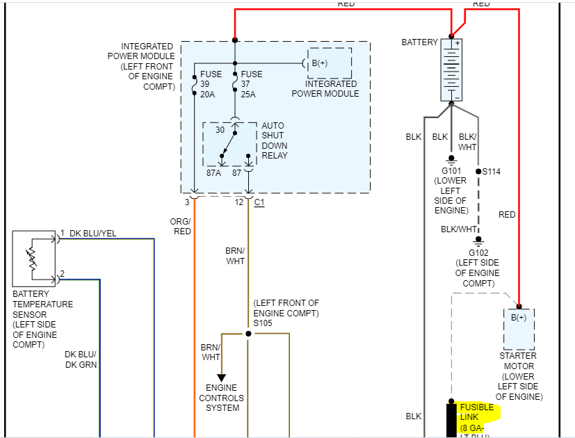
That fat output wire runs directly back to the battery's positive post, but normally with a fuse link wire spliced in somewhere. As such, you must find the same voltage on that stud and across the battery all the time. With the engine not running, 12.6 volts indicates a good battery that is fully-charged. A good battery that is totally run down will measure around 12.2 volts. When you find it's closer to 11 volts or less, it has a shorted cell and must be replaced.

With the engine running, the alternator must develop between 13.75 and 14.75 volts. You'll also measure that right at the battery. If that charging voltage is too low, as you've been finding, no current will go back into the battery to keep it charged. The entire electrical system will have to run on the battery until it slowly runs down, typically within a half hour. If the charging voltage is considerably higher than 14.75 volts, the water will start to boil out of the acid in the battery.

The only time you'll find the voltages at the battery and at the alternator's output stud are different is when the fuse link wire is burned open. That's a slow-acting fuse device that takes some time to burn open. Do not replace them with regular wire. These will be a smaller diameter wire than the rest of the wire it protects, making it the weak link in the chain. It's a regular wire, but the insulation is designed to not burn or melt. You can buy replacement fuse link wire at any auto parts store. The color of the insulation denotes its current rating. You'll get a piece about 12" long which is plenty to cut and make two or three repairs.

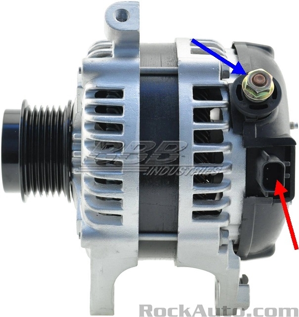
Only three things can go wrong with a fuse link wire feeding the alternator's output circuit. By far the most common is touching that output stud and anything metal on the engine at the same time with a wrench or other metal tool. This is why we always disconnect the battery before working in that area. The second cause is a defect inside the alternator. They all have, at a minimum, two sets of three "diodes". Those are one-way valves for electrical current flow. They are also the only thing that stops an alternator from placing a dead short across the battery when the engine is off. It's not that uncommon for one diode to short, but then the excessive heat developed usually causes them to burn open, (like they aren't even there). While very rare, if it didn't burn open, and later another diode in the other set of three were to short, that would create that dead short, then the fuse link wire would burn open. That is when you'd find 0.0 volts at the output stud, but 12.6 volts at the battery.

Also, when that happens, the alternator can't send what little current it can still develop back to the electrical system, so as the voltage regulator tries to run it harder and harder, the voltage on the output stud could reach 17 - 18 volts or more. That also is different than what you measure at the battery.

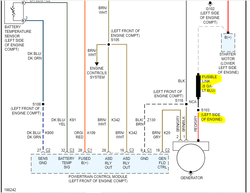
The third cause of this failure is when one of the splices on that fuse link wire corrodes apart. This too is rare, but it is more likely to occur on older GM vehicles. They commonly connect them to the end of the positive battery cable where it bolts to the starter. The starter isn't part of the circuit. It's just a convenient tie point so they didn't have to run that wire all the way back to the battery. That splice is down lower where it's closer to road salt.

When voltage tests tell you to suspect a fuse link wire is burned open, test them by gently tugging on them. A good one will act like a wire. A bad one will act like a rubber band.

There's a whole 'nuther story relating to the carbon track left behind inside the insulation when the wire arcs as it burns open. That can lead very experienced mechanics down the wrong diagnostic path due to voltmeters falsely picking up some voltage. To avoid this heartache, I always recommend using a test light instead of the voltmeter. Test lights require current flow to work, and that won't happen when the fuse wire is burned away.

To clarify my answer about that 12.6 volts, that has absolutely nothing to do with whether an alternator is good or not. That would equate to assuming a home water pump on your well is good because there's water in the pipes. In this sad comparison, the only thing you can assume is the check valve isn't leaking when the pump is not running.

It's those two voltages you found on the two smaller wires that tells the whole story. The voltage regulator watches system voltage, and if it were to decide it needs to run the alternator wide-open to meet the current demand, it would put roughly four, or maybe even five volts on the brown / gray wire. The brown / black wire goes right to ground, (0.00 volts), so that full four or five volts is "dropped" across the field coil that's spinning in the alternator. With the coil's resistance, this voltage will cause a maximum of very close to three amps to flow through it. That sets up the strongest electromagnetic field that can be developed, and that results in the highest possible amount of current being developed. Most of the time you'll only find one amp or less of current flow through the field coil. We don't actually waste time trying to measure that, because we get the same information from the voltage on that brown / gray wire. A common voltage to find is around two volts, give or take a little. The important point is ten volts is about as high as the regulator can supply, and indicates no matter how high it drives the field coil, system voltage isn't coming up to where it should be, (13.75 to 14.75 volts).

A simpler way to look at this is if the rest of the circuitry was working normally, you'd have 10.81 volts on one wire and 0.00 volts on the other one. That puts 10.81 volts across the field coil and creates a huge electromagnetic field. As it spins, that is what "induces" the voltage in the stationary "stator" coils where the output current is taken from. That equates to the water pump working really hard. Water pressure, and electrical pressure, (voltage) goes real high. That's not happening here.

What you found is the same voltage on both wires. (With such a tiny.02 volt difference, we consider them to be identical). The difference between them is 0.00 volts. No current is flowing through the field coil, no electromagnetic field is being developed, and no output voltage or current is being developed. System voltage doesn't rise any higher than the battery's voltage.

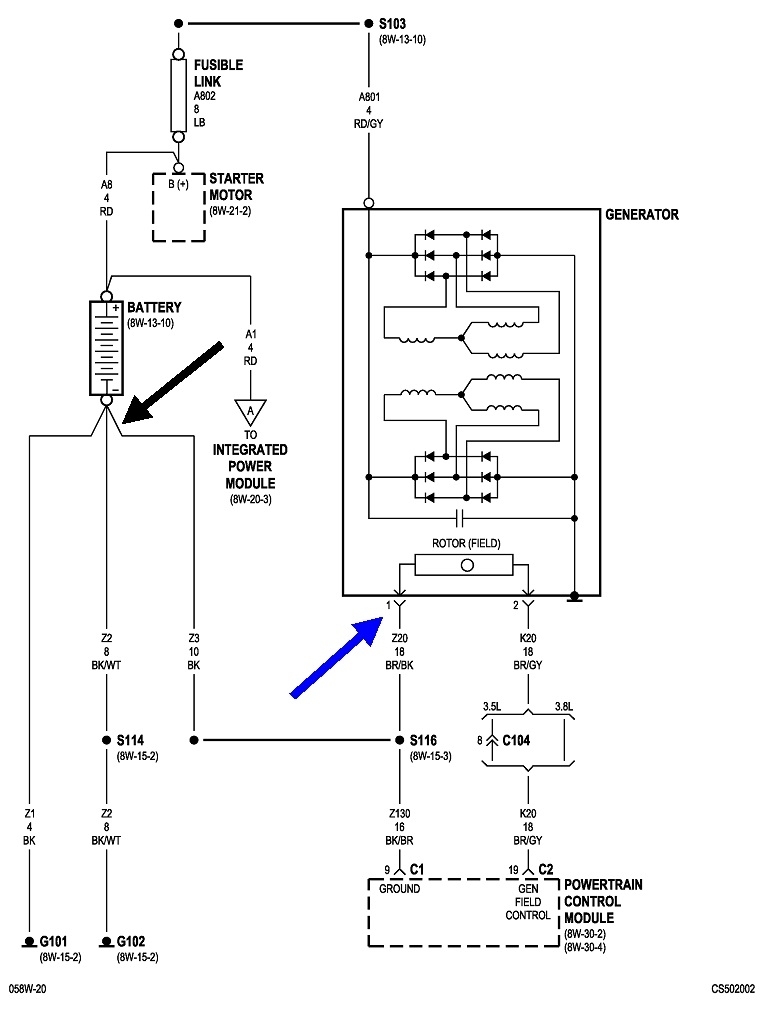
There's 0.00 volts on the other end of the brown / black wire where it connects to the battery's negative cable. You can't have two different voltages at any two places in a wire, unless there's a break between those two places. That's why, after all this glorious explanation, the voltage you found on the brown / black wire tells us there has to be a break in it.

You can jump that wire momentarily to ground to verify this wire has a break. I described doing that in my previous reply.

That test simply verifies there's a break in the brown / black wire. Now we have to find it. Many competent do-it-yourselfers would just run a new wire, but in my classes, that is always unacceptable, more so for all the other wires that aren't ground wires like this one is. We want to know exactly where the wire broke, and why, so we can address the cause before it happens to another wire in that harness. Things I've run into include a harness that fell down onto hot exhaust parts on a Stratus, then they melted through the insulation and the wires shorted to ground, a harness that got routed incorrectly after the engine was reinstalled, and the wires were rubbing on the sharp edge of a metal bracket, and a wire harness that was sliding back and forth on the inner fender as the engine rocked back and forth. That one took four years to show up once the outer covering, the wires' insulation, and the fender's paint rubbed through. The same thing was close to happening to three or four other wires in that bundle.

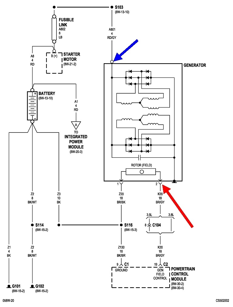
For your wire, a good suspect is a corroded splice S116 or that wire is corroded off at the terminal in the connector or at the battery cable. We can narrow down the list of suspects even more if we look at the wire designations. Right next to my blue arrow, the wire is listed as, "Z20 18BR / BK. "Z" circuits are ground wires or circuits. This is circuit "20" which just differentiates it from other circuits. It's an 18-gauge wire which is very small, indicating you don't expect it to carry very much current. It's color is brown with a black "tracer" or stripe.

As you follow that wire to the battery, note that after splice S116, it runs to the left, goes through another splice, then turns into circuit Z3, so it's a different part of that circuit.
More importantly, it's now a ten-gauge wire which is pretty large. A lot of current is expected to flow through that section, and with other circuits not shown here, we have to assume that current flows through the unidentified splice, then to a number of other systems. Since there's no symptoms from other things not working, we can assume this ten-gauge part of the wire is okay. That leaves the section between the two splices as the best suspect.

Now comes the hard part. Start by tugging on that wire by the connector. The wire is crimped to the terminal in one place, then right behind it, the insulation is trapped under another crimp. If the wire is well connected yet, you won't be able to pull it loose with light hand pressure. If it is corroded off, it will be rather easy to tug the insulation out of its part of the terminal.

If the wire is okay there, the break has to be somewhere along it. The only course of action then is to dig through the harness and follow that wire until you find the break. Once you identify where it is broken, we can figure out why and the best way to repair it.
Was this
answer
helpful?
Yes
No
Tuesday, April 11th, 2023 AT 5:13 PM
Tiny
CDB52
  • MEMBER
  • 10 POSTS
No worries about the misplacement of your reply; it happens sometimes. And besides, urgency isn't needed at this particular time as I've returned back to work (roustabout in the oil fields of West Texas). Tomorrow evening, I shall be back on green grass and under the hood. I sure appreciate your responses and the in-depth and easily digestible nature in which you deliver them. I know typing it all out can be time-consuming so, thank you. I'll be back with an update soon.
Was this
answer
helpful?
Yes
No
Tuesday, April 11th, 2023 AT 6:12 PM
Tiny
JACOBANDNICKOLAS
  • MECHANIC
  • 108,217 POSTS
Hi,

I noticed you haven't been contacted for a couple of days. Have you been able to make any progress?

If not, here is what I suggest. Remove the alternator and have it bench tested just to confirm the "new" alt works properly.

If it checks good, the PCM will likely need to be replaced. The amount of DC current produced by the alternator is controlled by the EVR (field control) circuitry contained within the PCM.

I attached the wiring schematic below, so you have a reference. Note: At the alternator will be a red wire with a gray tracer. Confirm it has power. There is a fusible link between the starter motor and alternator. If it failed, the alternator won't get power and won't charge.

Additionally, confirm the brown wire with a black tracer has continuity to ground. If you have both power and ground to the alternator, either the PCM has failed or there is a broken connection at some point.

Let us know if this helps or if you have other questions.

Take care,

Joe
Was this
answer
helpful?
Yes
No
Thursday, April 13th, 2023 AT 7:05 PM
Tiny
CARADIODOC
  • MECHANIC
  • 33,743 POSTS
Hi brother Joe. We're past that point already. There has to be a break in the brown / black wire. That's the ground wire for the field circuit, but it has over ten volts on it. The same voltage is on both field wires, so there's no current flow and it's not building its electromagnetic field. Keep watching for an update.
Was this
answer
helpful?
Yes
No
Friday, April 14th, 2023 AT 6:58 PM
Tiny
CDB52
  • MEMBER
  • 10 POSTS
Morning fellas, I wish I had an update on the charging system in question but unfortunately, I've yet to make it back to green grass, still on the rig. Sunday there will be an update. Thanks for your patience.
Was this
answer
helpful?
Yes
No
Saturday, April 15th, 2023 AT 4:04 AM

Please login or register to post a reply.

Sponsored links