Hi and thanks for using 2CarPros.
First, I am going to provide the directions for removing and replacing the cylinder head. I see you got the valve cover off, but I am going to provide the directions in order from start to finish. The directions include valve removal. I didn't know if you needed that or not, so I'm adding them. The attached pictures correlate with these directions. After these directions, you will need the directions for installing the timing belt. That must be done correctly.
_____________________________________
REMOVAL AND INSTALLATION --- The first 30 pictures correlate with these directions.
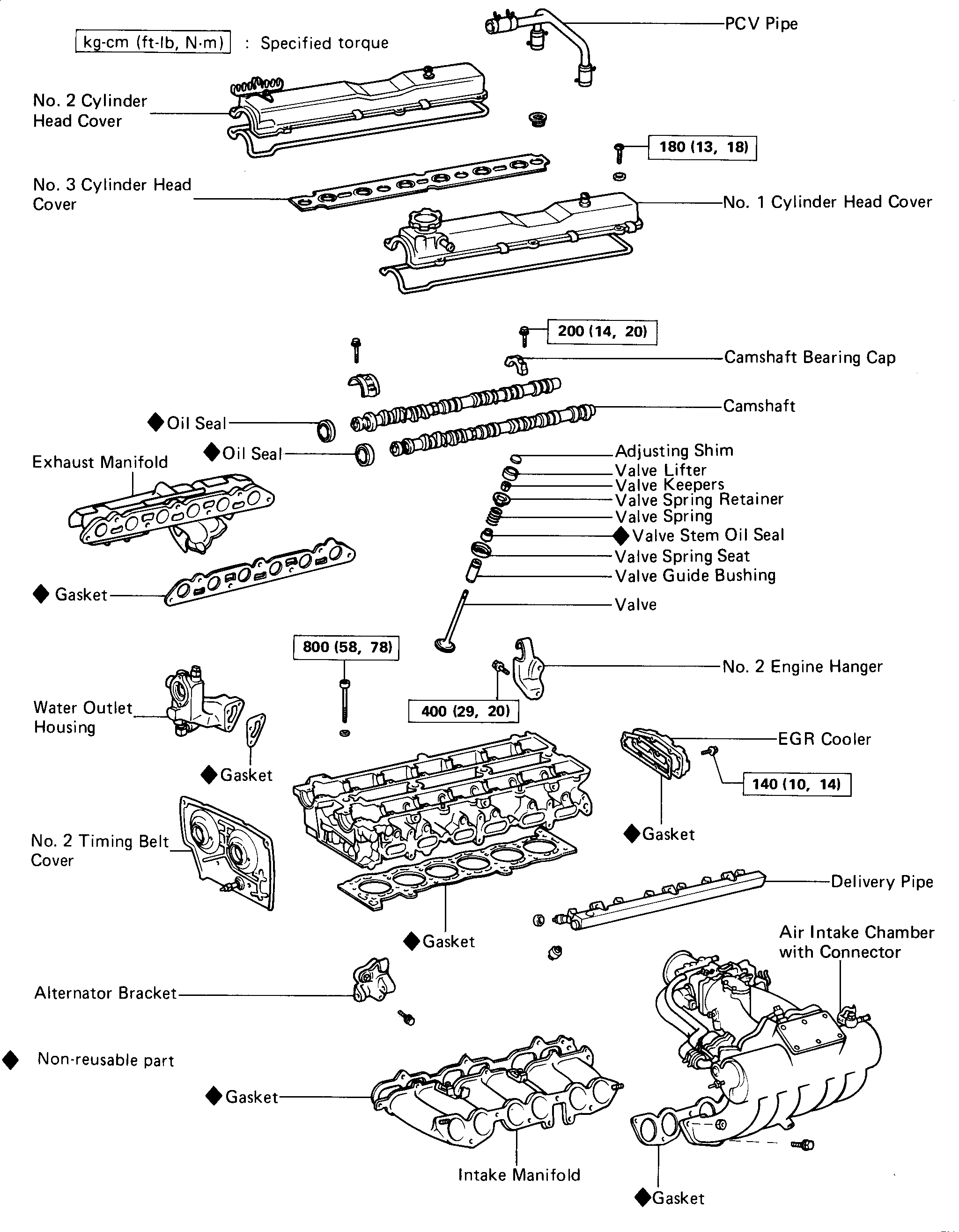
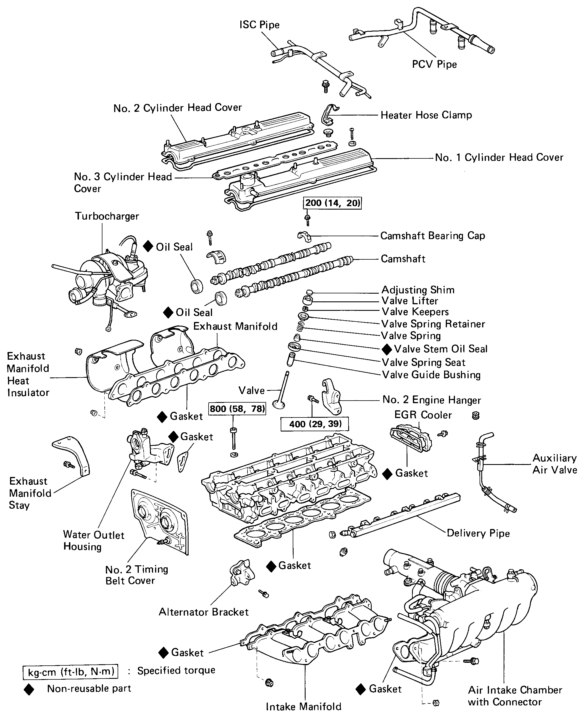
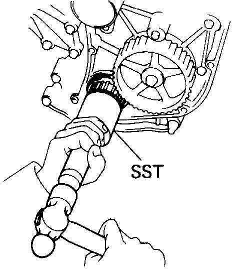
CYLINDER HEAD COMPONENTS (7M-GE) COMPONENTS (7M-GTE)
PREPARATION FOR REMOVAL
1. DISCONNECT CABLE FROM NEGATIVE TERMINAL OF BATTERY E
2. DRAIN COOLANT
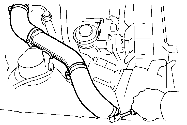
3. DISCONNECT EXHAUST PIPE FROM EXHAUST MANIFOLD
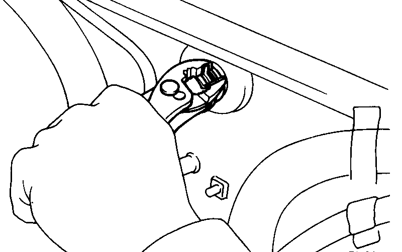
4. DISCONNECT FOLLOWING CABLE:
(a)Cruise control cable
(b)Accelerator cable
(c)(A/T) Throttle cable
5. DISCONNECT GROUND STRAP FROM ENGINE REAR SIDE
6. (7M-GE)
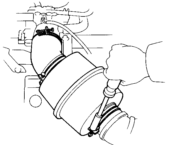
REMOVE NO.1 AIR CLEANER HOSE WITH INTAKE AIR CONNECTOR PIPE
(7M-GTE)
REMOVE NO.4 AIR CLEANER PIPE WITH NO.1 AND NO.2 AIR CLEANER HOSE
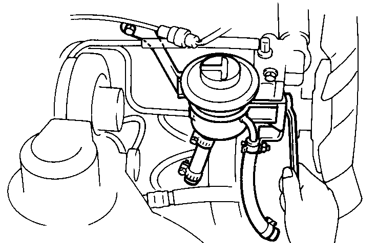
7. DISCONNECT FOLLOWING HOSES:
(b)Charcoal canister hose
(c)Brake booster hose
8. REMOVE RADIATOR INLET HOSE
9. DISCONNECT HEATER INLET HOSE
REMOVAL OF CYLINDER HEAD
1. REMOVE ALTERNATOR
(a)Disconnect the No.3 PCV hose.
(b)Remove the drive belt.
(c)Remove the alternator and adjusting bar.
2. (7M-GTE)
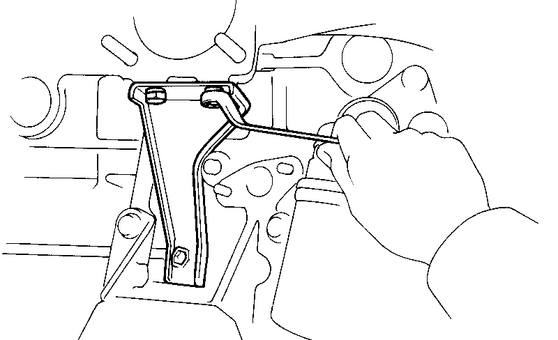
REMOVE PS RESERVOIR TANK
Remove the two bolts, nut and reservoir tank with bracket.
3. (7M-GTE)
REMOVE CAM POSITION SENSOR
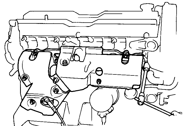
4. REMOVE AIR INTAKE CHAMBER WITH CONNECTOR
(a)Remove the PCV pipe.
(b)Disconnect following wires:
- (7M-GE)
Cold start injector connector
- Throttle position sensor connector
- ISC valve connector
(c)Disconnect following hoses:
- BVSV hose from throttle body
- EGR hoses from throttle body
- Vacuum transmitting pipe hose from intake chamber
- Pressure regulator hose
- PS air hose
- VSV hoses (for FPU)
- (7M-GE) Diaphragm hose
(d)Disconnect following hoses:
- (7M-GTE)
Auxiliary air pipe hose from vacuum transmitting pipe hose
No.1 water by-pass hose from ISC valve
- (7M-GE)
No.3 water by-pass hose from throttle body
- (7M-GTE)
No.3 water by-pass hose from water by-pass pipe
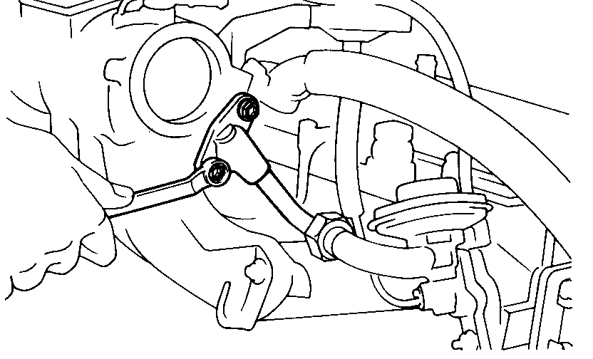
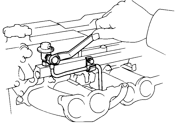
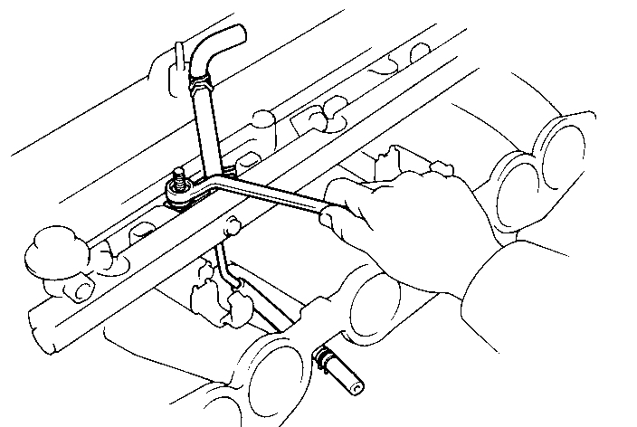
(e)Remove the EGR pipe mounting bolts.
(f)Remove the manifold stay mounting bolts.
(g)(7MGE)
Remove the throttle body bracket.
(7M-GTE)
Remove the ISC pipe.
(h)(7M-GTE)
Remove the air intake connector mounting bolt.
(i)(7M-GE)
Remove the air intake connector bracket mounting bolts.
(j)Remove the cold start injector tube.
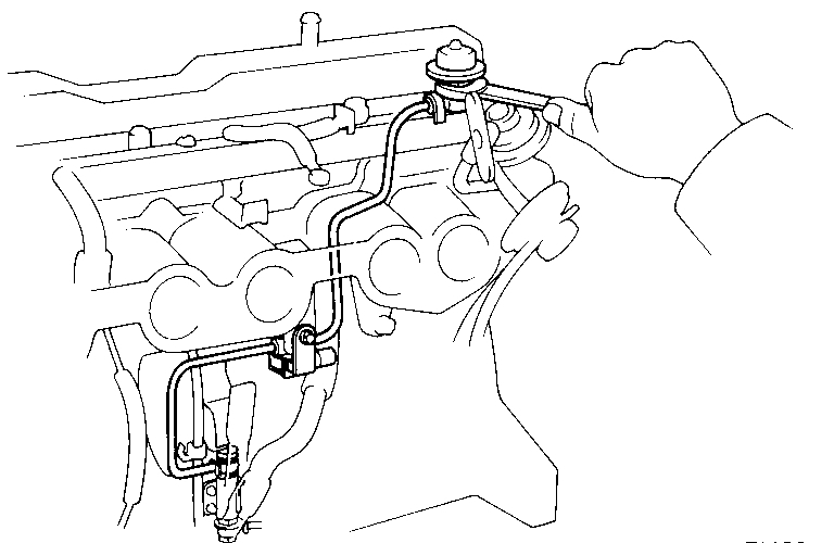
(k)Remove the EGR vacuum modulator from the bracket.
(l)Disconnect the engine wire from the clamps of intake chamber.
(m)Remove the two nuts, five bolts, vacuum transmitting pipes and intake chamber with connector and gasket.
(n)(7M-GTE) Disconnect the cold start injector connector.
5. (7M-GTE) REMOVE IGNITION COIL WITH BRACKET
6. REMOVE ENGINE WIRE
(a)Disconnect following wires:
- Oxygen sensor connector
- Oil pressure sender gauge connector
- Water temp. sensor connector
- Water temp. sender gauge connector
- Cold start injector time switch connector
- (7M-GE) Distributor connector Injector connectors
- Three VSV connectors
- Knock sensor connector(s)
- Ground strap from intake manifold
- Check connector
- Solenoid resister connector
- (7M-GE) Ignition coil connector
- (7M-GTE) Igniter connectors
- Noise filter connector
- Main relay connector
- Starter connector (terminal 50)
- Transmission connectors
(b)Remove the engine wire from the four clamps.
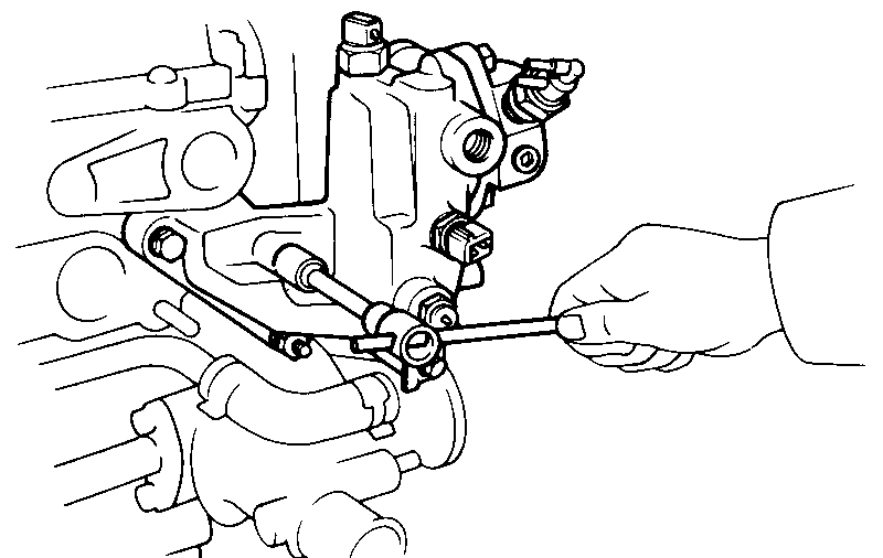
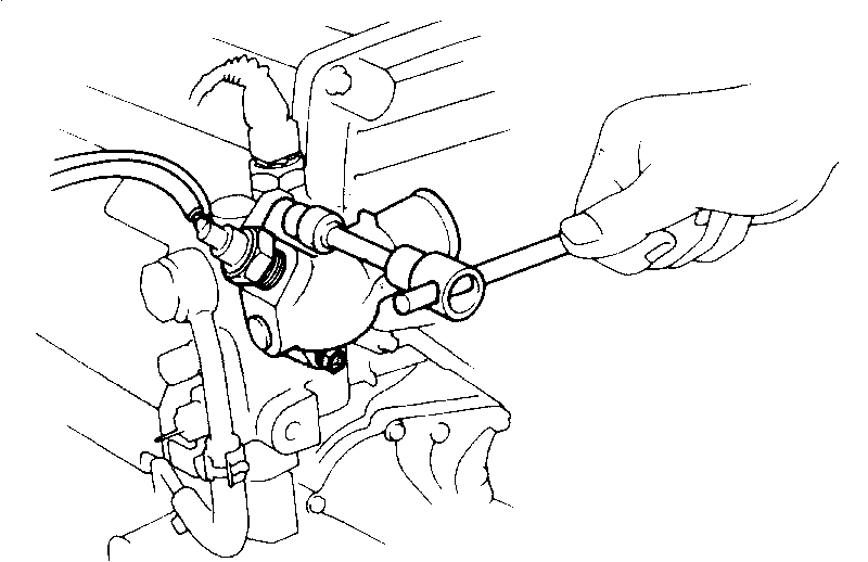
7. REMOVE PULSATION DAMPER, VSV AND NO.1 FUEL PIPE
8. REMOVE NO.3 FUEL PIPE
(a)Disconnect the fuel hose from the fuel support.
(b)Remove the bolt, union bolt, NO.3 fuel pipe and gaskets.
9. (7M-GTE) REMOVE AUXILIARY AIR PIPE
10. (7M-GE) REMOVE HIGH-TENSION CORDS AND DISTRIBUTOR
11. (7M-GE) REMOVE OIL DIPSTICK
12. (7M-GTE)
REMOVE TURBOCHARGER
13. REMOVE EXHAUST MANIFOLD
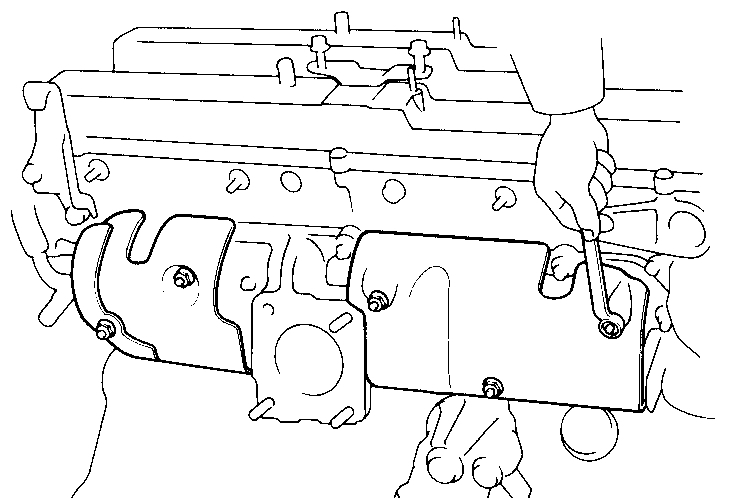
(a)(7M-GTE) Remove the five nuts and heat insulators.
(b)(7M-GTE) Remove the three bolts and exhaust manifold stay.
(c)Remove the seven nuts, exhaust manifold and gasket.
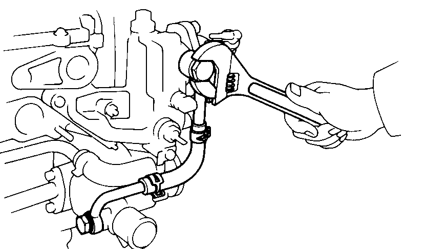
14.REMOVE WATER OUTLET HOUSING
(a)(7M-GE)
Remove the union bolts, union with No.4 water bypass hose and gaskets.
(b)Disconnect the No.6 water by-pass hose from the water by-pass pipe.
(c)Remove the bolt, two nuts, water outlet housing and gasket.
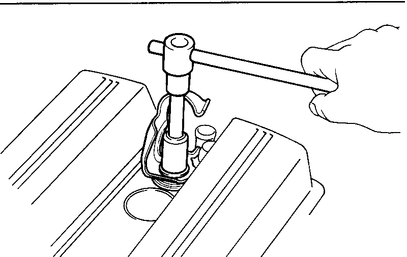
15. REMOVE CYLINDER HEAD COVERS
(a)Remove the accelerator link.
(b)Remove the No.1 and No.2 cylinder head covers.
(c)Remove the heater hose clamp.
(d)Using SST, remove the No.3 cylinder head cover. SST 09923-00010
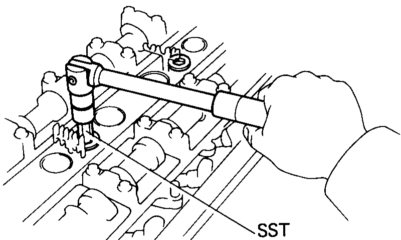
16. REMOVE SPARK PLUGS
17. REMOVE TIMING BELT AND CAMSHAFT TIMING PULLEYS
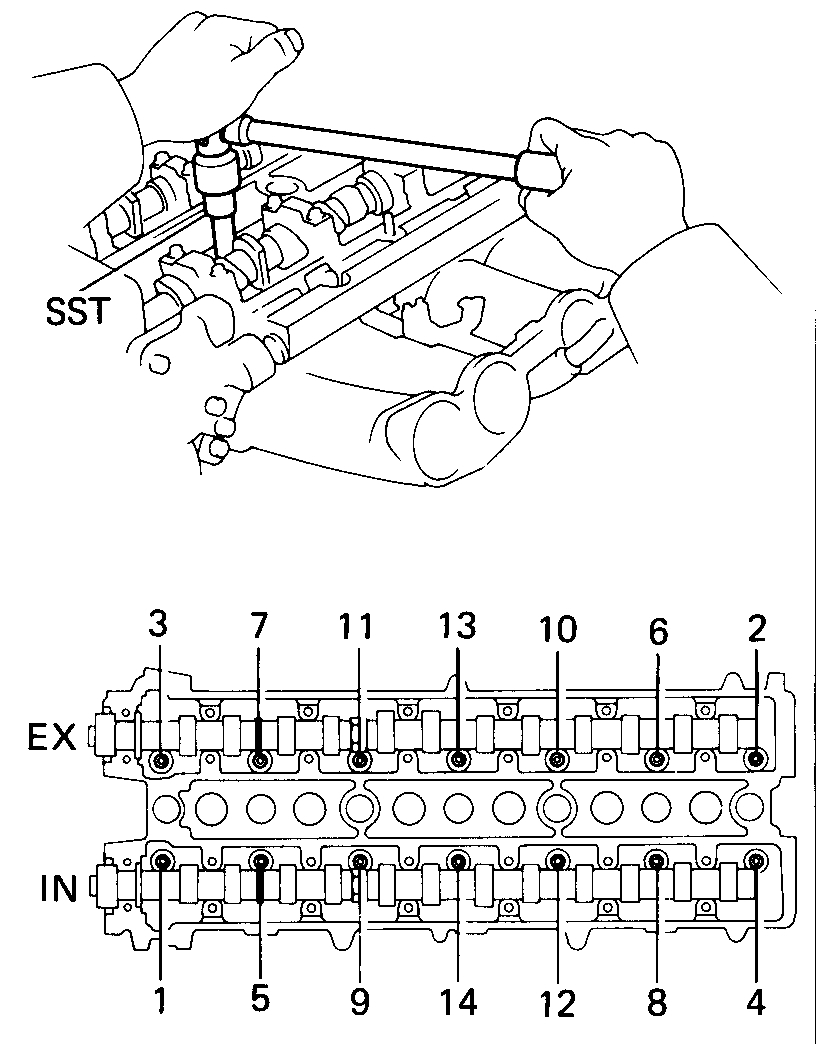
18. REMOVE CYLINDER HEAD
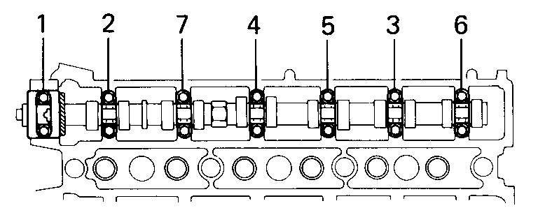
(a)Using SST, remove the head bolts gradually in three passes and in the numerical order shown. SST 09043-38100
CAUTION: Head warpage or cracking could result from removing bolts in incorrect order.
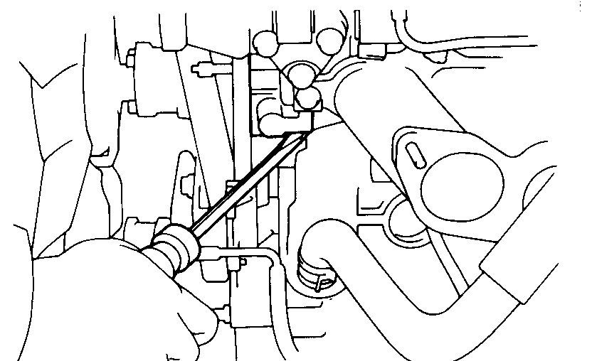
(b)Lift the cylinder head from the dowels on the cylinder block. As the cylinder head is lifted, separate the No.5 water by-pass hose from the union.
(c)Place the head on wooden blocks on a bench.
If the cylinder head is difficult to lift off, pry with a screwdriver between the cylinder head and block projection.
CAUTION: Be careful not to damage the cylinder head and block surface on the cylinder and head gasket side. Be careful not to damage the VSV.
DISASSEMBLY OF CYLINDER HEAD
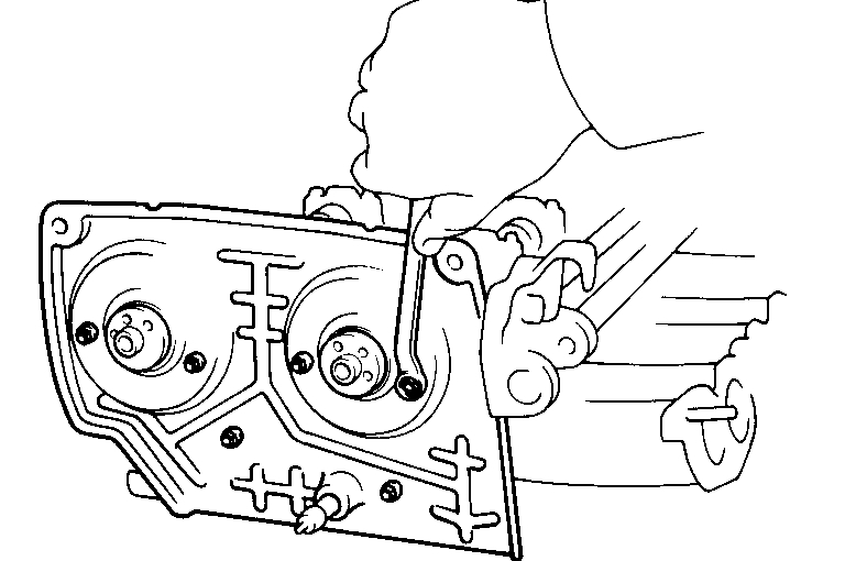
1. REMOVE NO.2 TIMING BELT COVER
2. REMOVE ALTERNATOR BRACKET
3. REMOVE HEATER INLET HOSE
4. REMOVE HEATER UNION
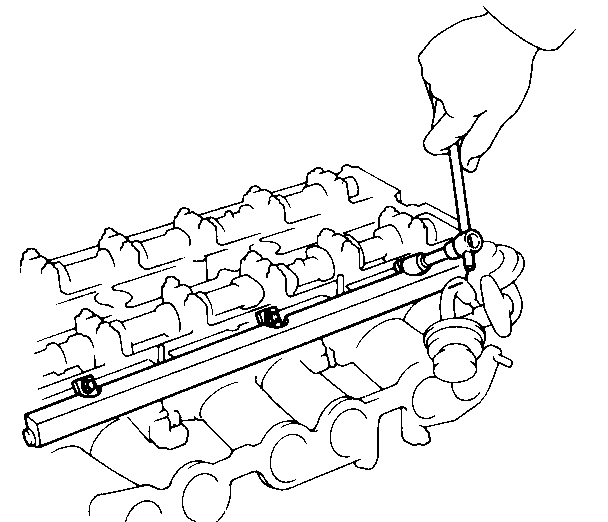
5. REMOVE DELIVERY PIPE WITH INJECTORS
(a)Remove the three bolts, and then remove the delivery pipe with the injectors.
NOTE: When removing the delivery pipe, be careful not to drop the injectors.
(b)Remove the six insulators and three spacers from the cylinder head.
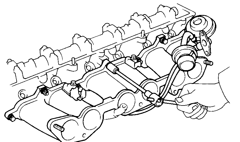
6. REMOVE INTAKE MANIFOLD
Remove the four nuts, seven bolts, EGR valve, VSV, intake manifold and gasket.
7. REMOVE NO.2 ENGINE HANGER AND GROUND STRAP
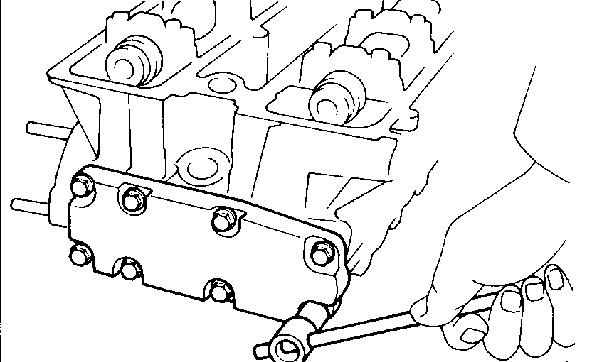
8. REMOVE EGR COOLER
9. REMOVE BEARING CAPS AND CAMSHAFTS
(a)Loosen each bearing cap bolt a little at a time and in the sequence shown in the figure.
(b)Remove the camshaft bearing caps, oil seal and camshaft.
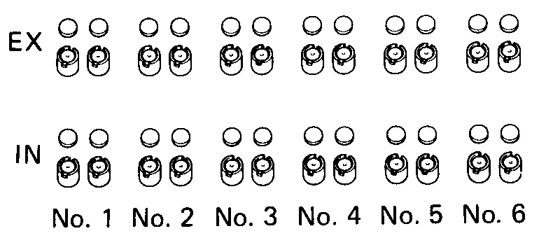
10. REMOVE VALVE LIFTERS WITH SHIMS
Arrange the valve lifters and shims in order.
11. REMOVE VALVES
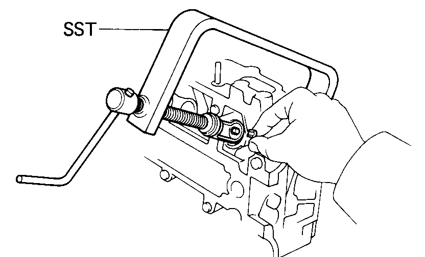
(a)Using SST, press the valve spring and remove the two keepers. SST 09202-70010
(b)Remove the spring retainer, valve spring, seat and valve.
(c)Pry out the oil seal.
NOTE: Arrange the valves, seats valve springs and retainers in order.
_________________________________________________
Here are the directions for removing and replacing the timing belt. All remaining pictures correlate with these directions.
Timing Belt Replace
Vehicle Engine, Cooling and Exhaust Engine Timing Components Timing Belt Service and Repair Procedures Timing Belt Replace
TIMING BELT REPLACE
REMOVAL OF TIMING BELT
1. REMOVE RADIATOR
2. REMOVE SPARK PLUGS
3 REMOVE WATER OUTLET
Remove the two bolts, water outlet and thermostat with the gasket.
4. REMOVE A/C BELT
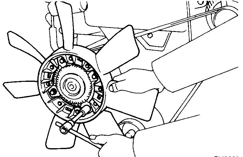
5. REMOVE FAN AND ALTERNATOR DRIVE BELT
6. REMOVE PS BELT
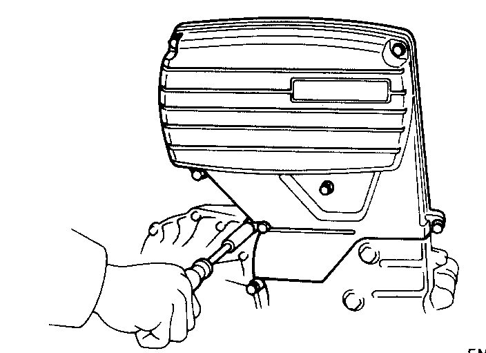
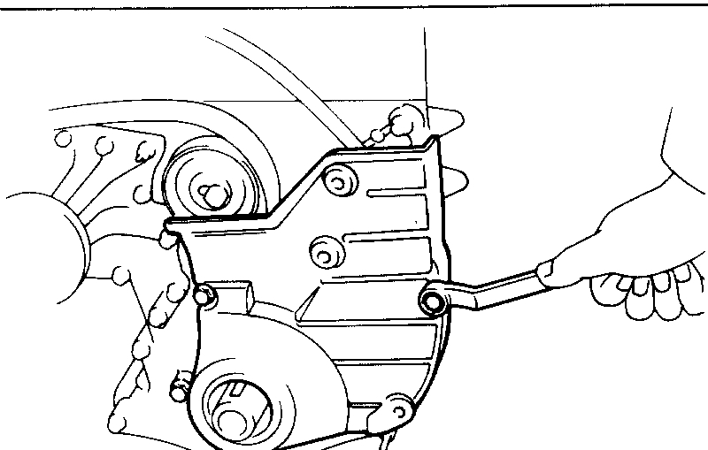
7. REMOVE NO.3 TIMING BELT COVER
Remove the five bolts, nut and No.3 timing belt cover with the gasket.
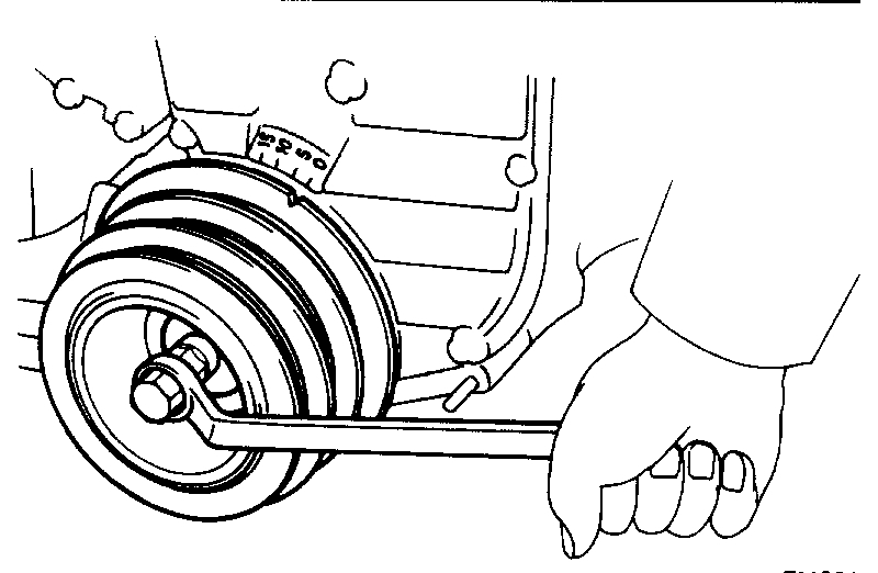
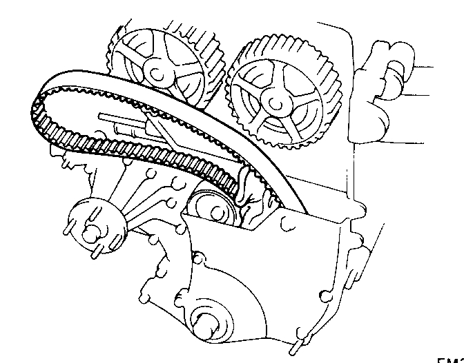
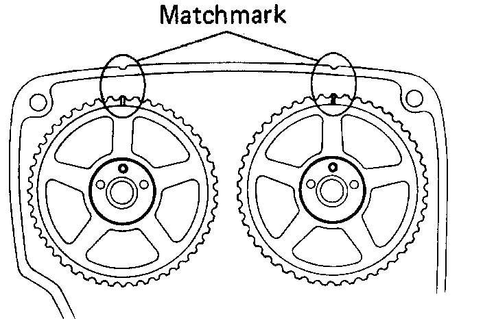
8. SET NO.1 CYLINDER AT TDC/COMPRESSION
(a)Turn the crankshaft pulley and align its groove with the "0" mark on the No.1 timing belt cover.
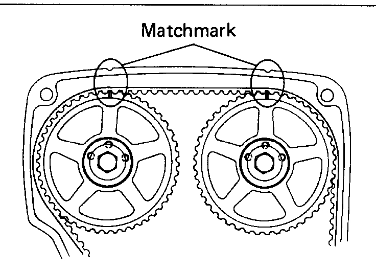
(b)Check that the matchmarks on the camshaft timing pulleys and No.2 timing belt cover are aligned. If not, turn the crankshaft pulley one complete revolution.
9. REMOVE TIMING BELT FROM CAMSHAFT TIMING PULLEYS
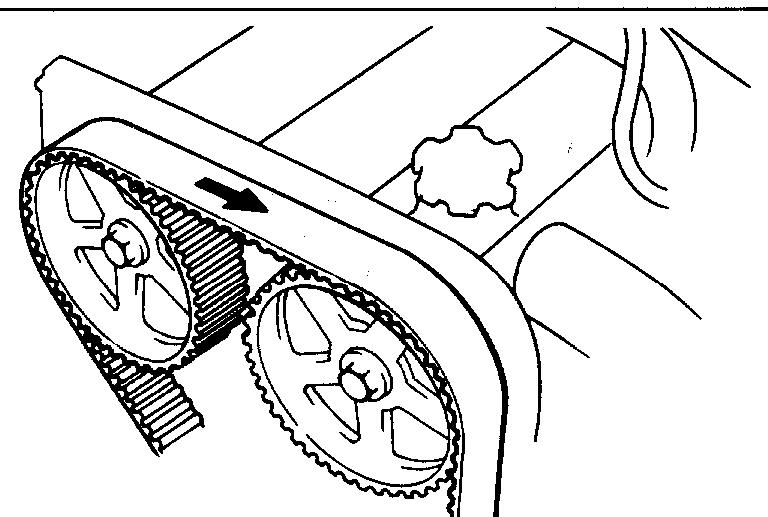
NOTE: If reusing the timing belt, draw a direction arrow on the belt (in direction of engine revolution).
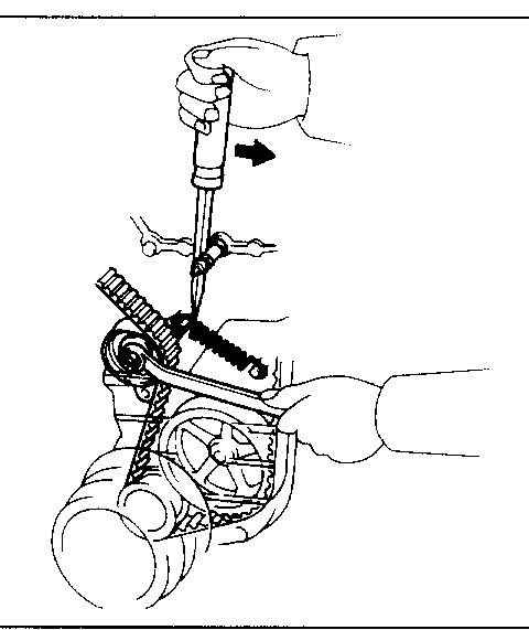
(a)Loosen the idler pulley bolt and shift it left as far as it will go with a screwdriver and wrench.
(b)Temporarily tighten the set bolt and then relieve the timing belt tension.
(c)Remove the belt from the camshaft timing pulleys.
NOTE:
- Support the belt so the meshing of the crankshaft timing pulley and timing belt does not shift. Be careful not to drop anything inside the timing belt cover.
- Do not allow the belt to come into contact with oil, water and dust.
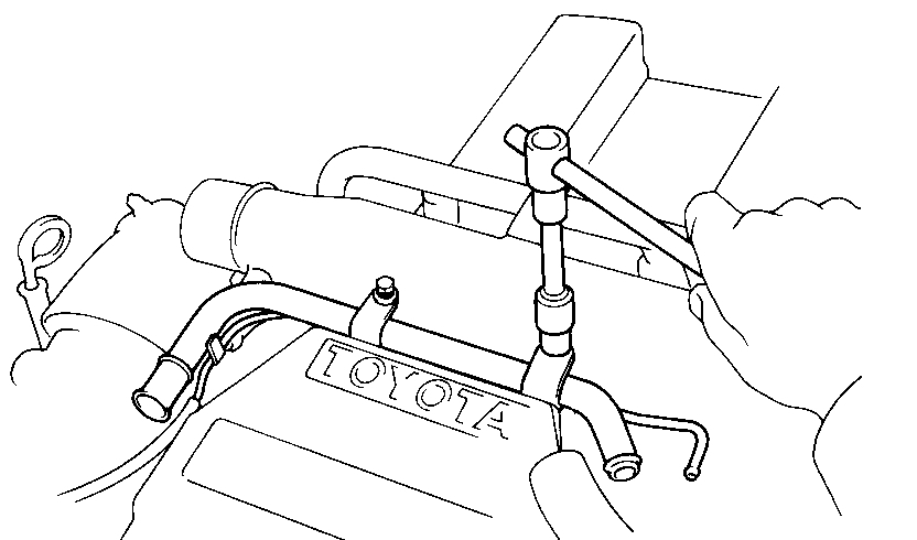
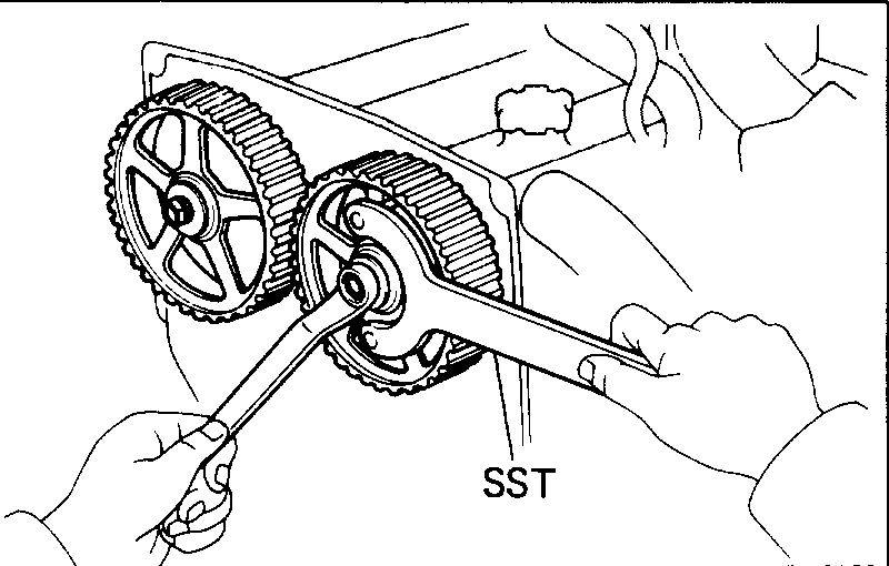
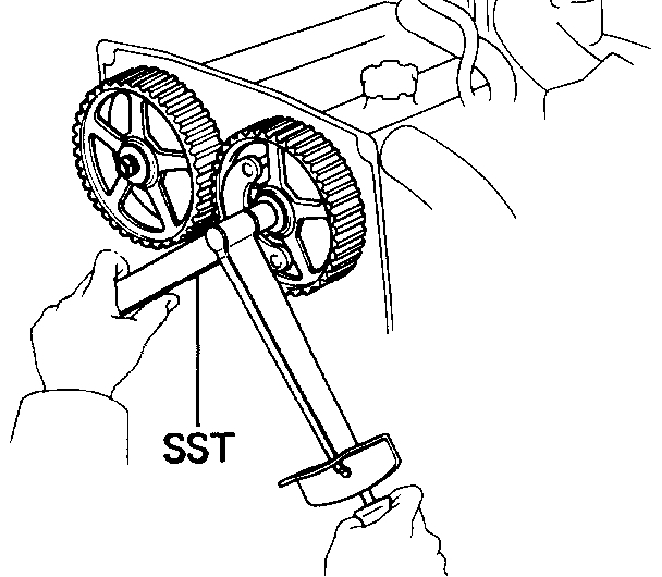
10. REMOVE CAMSHAFT TIMING PULLEYS
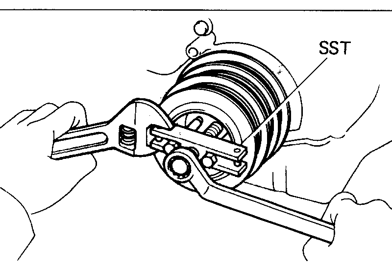
Using SST to hold the pulley, remove the pulley bolt, timing pulley and match pin. SST 09278-54012
CAUTION: Do not make use of the timing belt tension when removing and installing the pulley bolts.
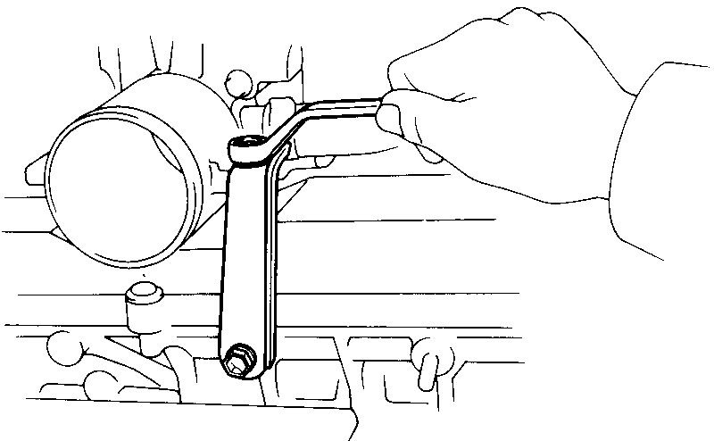
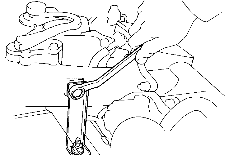
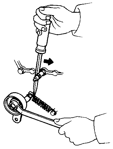
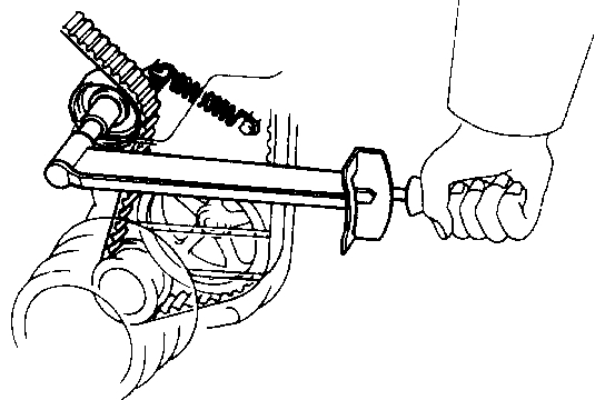
11. REMOVE CRANKSHAFT PULLEY
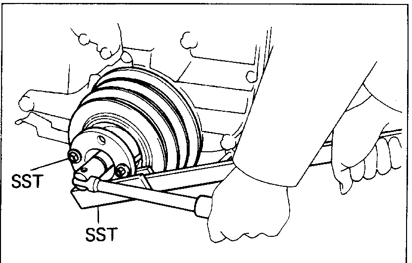
(a)Using SST to hold the crankshaft pulley, loosen the pulley bolt. SST 09213-70010 and 09330-00021
(b)Remove SST and pulley bolt.
(c)Using SST, remove the pulley. SST 09213-31021
12. REMOVE PS AIR PIPE
13. REMOVE NO.1 TIMING BELT COVER
(a)Remove the A/C compressor without disconnecting hoses (d).
(b)Remove the nine bolts, nut, A/C idler pulley bracket, compressor bracket and No.1 timing belt cover.
14. REMOVE TIMING BELT
15. REMOVE IDLER PULLEY AND TENSION SPRING
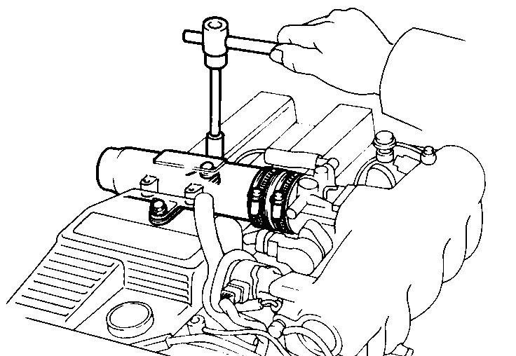
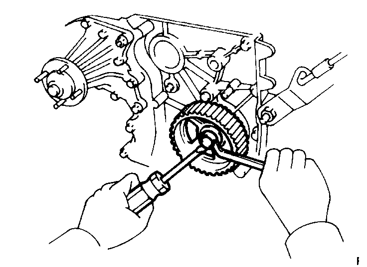
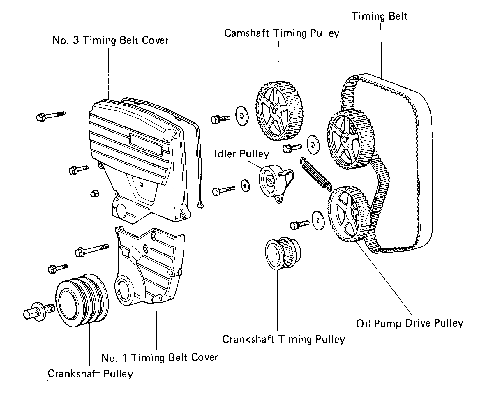
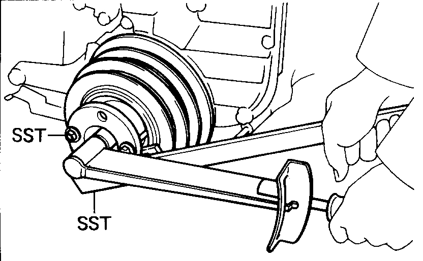
16. REMOVE CRANKSHAFT TIMING PULLEY
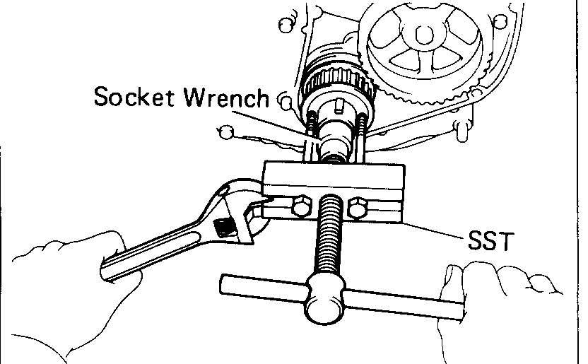
Using SST and socket wrench, remove the crankshaft timing pulley. SST 09213-60017
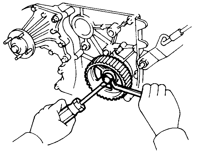
17. REMOVE OIL PUMP DRIVE PULLEY
Using a screwdriver to hold the pulley, remove the pulley bolt and pulley.
INSTALLATION OF TIMING BELT
1. IN STALL OIL PUMP DRIVE PULLEY
(a)Install the pulley and bolt.
(b)Using a screwdriver to hold the pulley, torque the pulley bolt.
Torque: 220 kg-cm (16 ft-lb, 22 N.m)
2. INSTALL CRANKSHAFT TIMING PULLEY
Using SST and hammer, drive in the pulley. SST 09214-60010
3. TEMPORARILY INSTALL IDLER PULLEY AND TENSION SPRING
(a)Install the idler pulley and tension spring.
Torque: 500 kg-cm (36 ft-lb, 49 N.m)
(b)Pry the idler pulley toward the left as far as it will go and temporarily tighten it.
NOTE: Remove any oil or water on the idler pulley and keep it clean.
4. TEMPORARILY INSTALL TIMING BELT
CAUTION: The engine should be cold.
NOTE: If reusing the timing belt, install it with the rotation direction mark pointing in the same direction as before disassembly. Install the timing belt on the crankshaft timing pulley, oil pump drive pulley and idler pulley
5. INSTALL NO.1 TIMING BELT COVER
(a)Install the No.1 timing timing belt cover, A/C compressor bracket and idler pulley bracket with the nine bolts and nut.
(b)Install the A/C compressor.
6. INSTALL PS AIR PIPE
7. INSTALL CRANKSHAFT PULLEY
(a)Align the pulley set key with the key groove of the pulley.
(b)Install the pulley.
bolt.SST 09213-70010 and 09330-00021
Torque: 2,700 kg-cm (195 ft-lb, 265 N.m)
8. SET NO.1 CYLINDER TO TDC/COMPRESSION OF CRANKSHAFT
Turn the crankshaft pulley and align its groove with the "0" mark on the No.1 timing belt cover.
9. INSTALL CAMSHAFT TIMING PULLEYS
(a)Align the timing pulley matchmark with the No.2 timing belt cover matchmark.
(b)Install the timing pulley.
(c)Install the pin to the hole.
NOTE: When replacing the camshaft or the camshaft timing pulley align the center holes of the camshaft and timing pulleys, as shown in the illustration and insert the straight pin.
- When resuing the camshaft or camshaft timing pulleys:
Checking that the straight pin hole position is in the same position it was at disassembly, insert the straight pin.
(d)Install the washer and pulley bolt.
(e)Using SST 09278-54012
Torque: 500 kg-cm (36 ft-lb, 49 N.m)
(f)Check that the matchmarks on the camshaft timing pulley are aligned with those on the No.2 timing belt cover.
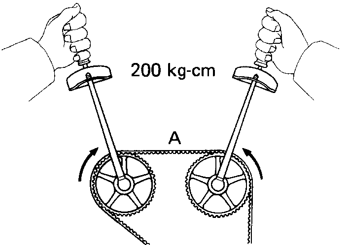
10. INSTALL TIMING BELT
(a)Install the timing belt to the IN side and EX side.
(b)Loosen the idler pulley bolt, and torque the idler pulley bolt.
Torque: 500 kg-cm (36 ft-lb, 49 N.m)
NOTE: Make sure that the timing belt tension at A is equal to that at B. If not, readjust with the idler pulley.
(c)Turn the crankshaft pulley two revolutions clockwise from TDC to TDC.
(d)Check that the matchmarks on the camshaft timing pulley are aligned with those on the No.2 timing belt cover.
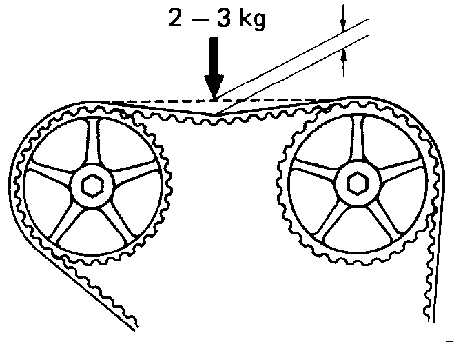
11. CHECK TIMING BELT TENSION
(a)Turn both the intake and exhaust camshaft pulleys inward at the same time to slacken the timing belt at position A.
(b)Measure the timing belt deflection as shown.
Belt deflection at 2 - 3 kg (4.4 - 6.6 lb, 20 - 29 N):
Cold Used belt 5 - 7 mm (0.20-0.28 in.)
New belt 4 - 6 mm (0.16-0.24 in.)
Hot (Referance) 3 - 5 mm (0.12-0.20 in.)
If the measurement is not within in limit, adjust by the idler pulley.
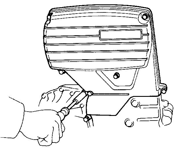
12. INSTALL NO.3 TIMING BELT COVER
Install a gasket and the belt cover with the five bolts as shown.
13. INSTALL PS BELT
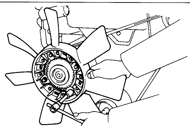
14. INSTALL ALTERNATOR DRIVE BELT AND FAN
Torque: Fan 55 kg-cm (48 in.-lb, 5.4 N.m)
Adjusting bolt 130 kg-cm (9 ft-lb, 5.4 N.m)
15. INSTALL A/C BELT
16. INSTALL WATER OUTLET
Install the thermostat with gasket and water outlet with the two bolts.
17. INSTALL SPARK PLUGS
18. INSTALL RADIATOR
19. INSTALL NO.1 AIR CLEANER HOSE WITH INTAKE AIR CONNECTOR PIPE
20. START ENGINE
Warm up the engine and inspect for leaks.
21. ROADTEST
Road test vehicle.
22. RECHECK COOLANT LEVEL
_______________
I hope this helps. Let me know if you have other questions.
Take care,
Joe
Images (Click to enlarge)
Jan 3, 2019 at 4:41 PM