Hi and thanks for using 2carpros.com.
Here are the directions and specs for the front control arm:
__________________
Lower Arm - Front
Vehicle Steering and Suspension Suspension Control Arm Service and Repair Procedures Front Lower Arm - Front
LOWER ARM - FRONT
Lower Arm - Front
Removal and Installation
CAUTION: Suspension fasteners are critical parts because they affect performance of vital parts and systems and their failure can result in major service expense. A new part with the same part number must be installed if installation becomes necessary. Do not use a replacement part of lesser quality or substitute design. Torque values must be used as specified during reassembly to make sure of correct retention of these parts.
1. With the vehicle in NEUTRAL, position it on a hoist. For additional information, refer to Maintenance/Service and Repair.
2. Using a suitable jack, support the front wheel knuckle at the rear lower ball joint.
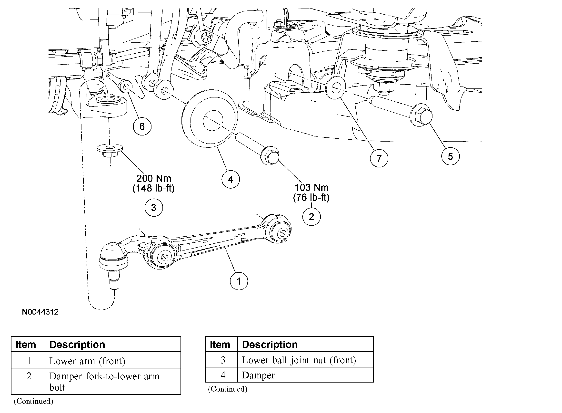
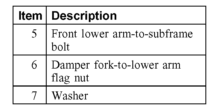
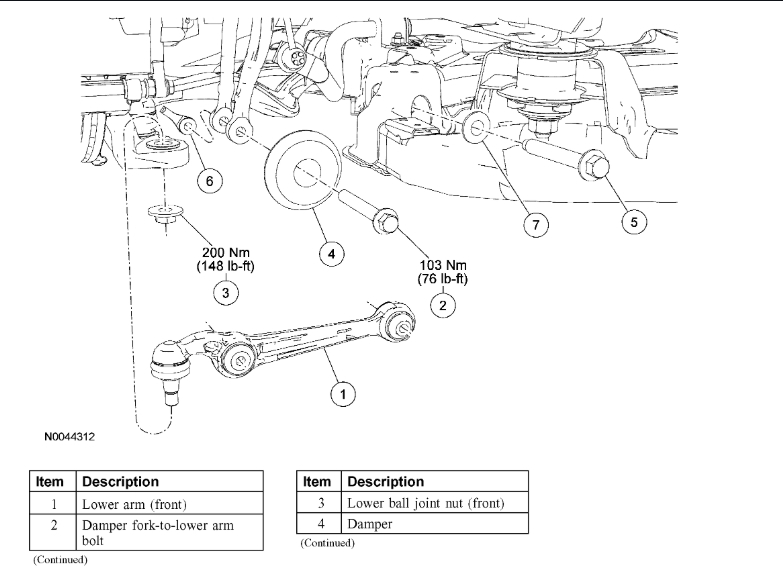
3. Remove the front lower arm-to-subframe bolt and washer and remove the front lower arm.
^ Discard the bolt and washer.
^ To install, tighten to 65 Nm (48 ft. lbs.), then tighten an additional 90 degrees.
4. Remove the damper fork-to-lower arm bolt flag nut and damper.
^ Discard the bolt and flag nut.
^ To install, tighten to 103 Nm (76 ft. lbs.) with the suspension at the bushing fastener tightening position.
5. Remove and discard the front lower ball joint nut.
^ To install, tighten to 200 Nm (148 ft. lbs.).
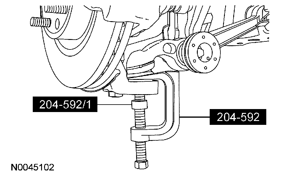
6. CAUTION: When the lower ball joint is separated from the wheel knuckle, the lower arm may strike the outer constant velocity (CY) joint boot with enough force to damage the boot clamp. This will result in a loss of grease from the outer CV joint. Place a block of wood, or similar item, between the lower arm and the outer CV joint to prevent the lower arm from striking the outer CV joint.
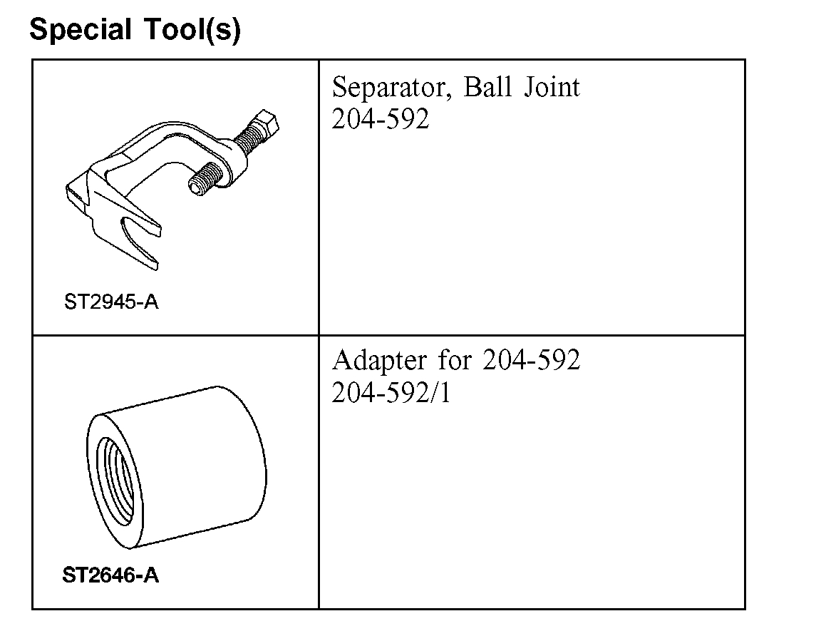
NOTE: Once pressure is applied to the ball joint with the special tool, it may be necessary to tap the wheel knuckle at the ball joint area to separate the ball joint from the wheel knuckle.
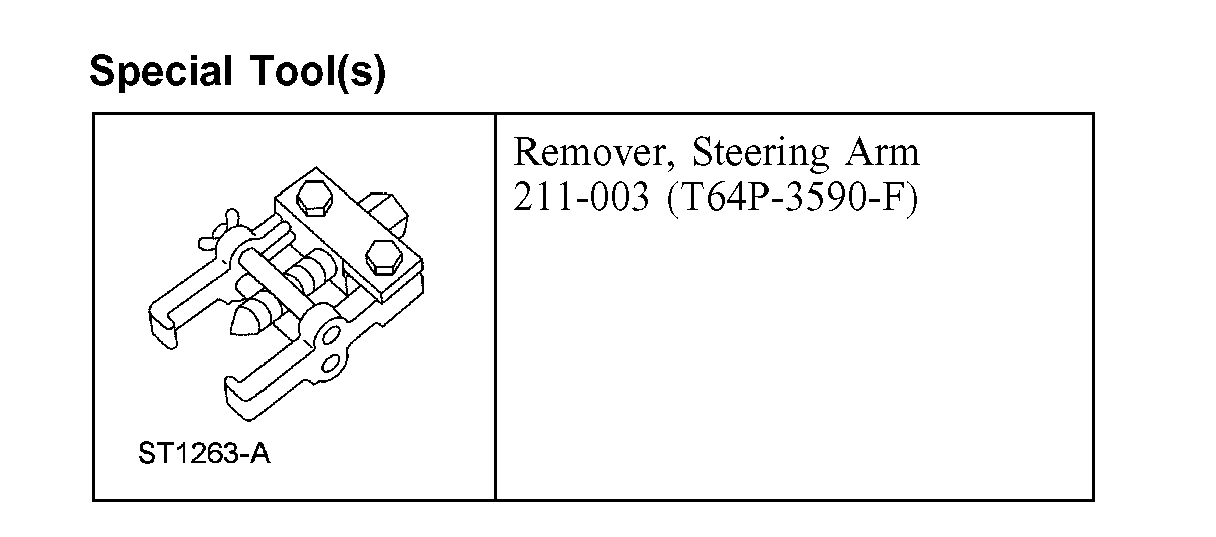
Using the special tools, separate the front lower ball joint from the wheel knuckle.
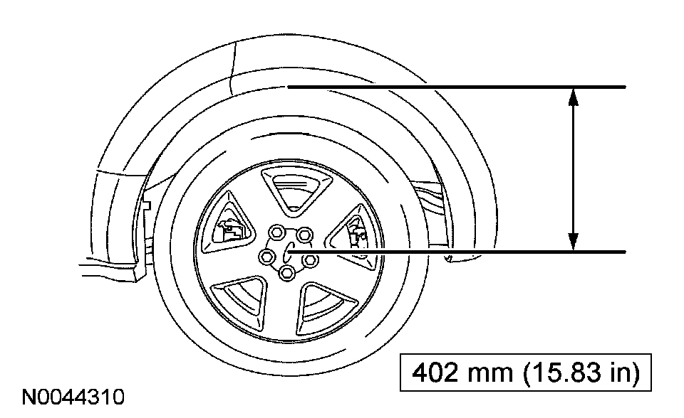
7. CAUTION: Before tightening any suspension bushing fasteners, the suspension must be at the bushing fastener tightening position. Use a suitable jack to raise the suspension until the distance between the center of the hub and the lip of the fender is equal to 402 mm (15.83 inch).
To install, reverse the removal procedure.
______________________________
Here are the directions for the front upper. By accident, I forgot to add the pics for this, so had to add them. The front upper control arm pics start with number 12. Sorry for the confusion.
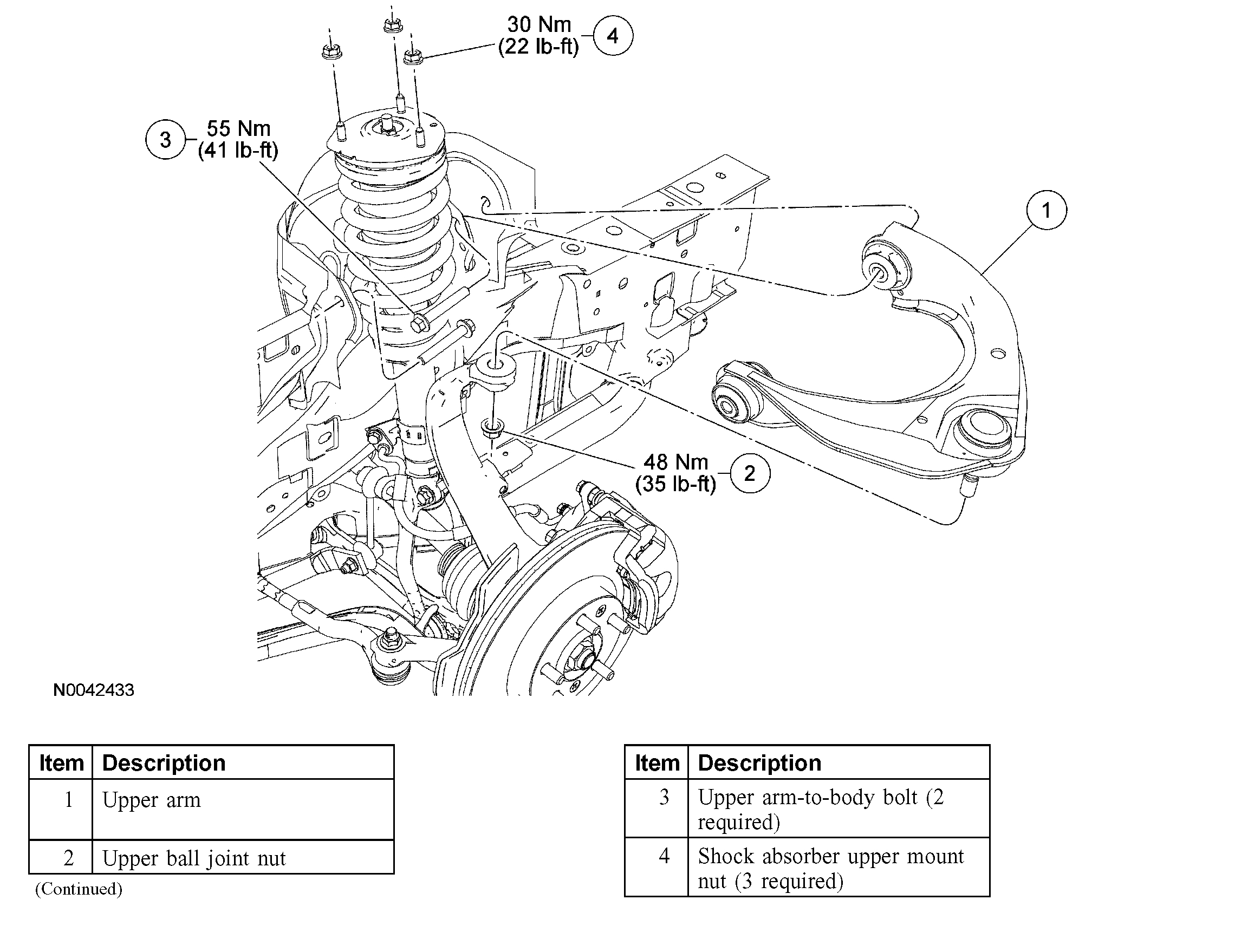
UPPER ARM
Upper Arm
Special Tool(s)
Removal
CAUTION: Suspension fasteners are critical parts because they affect performance of vital parts and systems and their failure can result in major service expense. A new part with the same part number must be installed if installation becomes necessary. Do not use a replacement part of lesser quality or substitute design. Torque values must be used as specified during reassembly to make sure of correct retention of these parts.
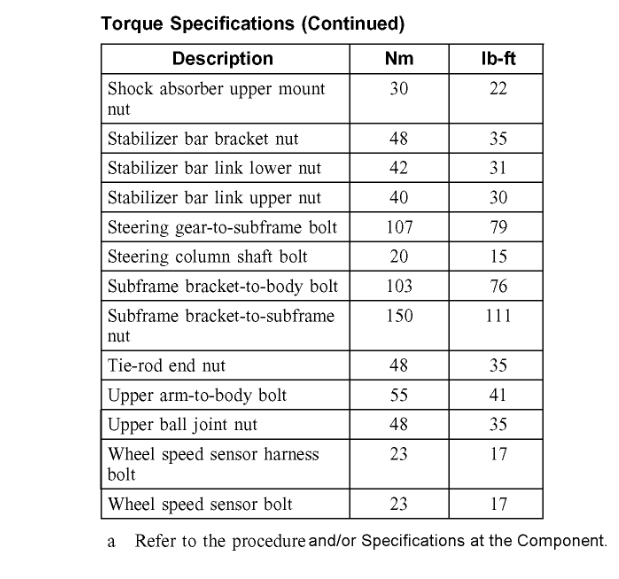
1. Remove and discard the 3 shock absorber upper mount nuts.
2. With the vehicle in NEUTRAL, position it on a hoist. For additional information, refer to Maintenance/Service and Repair.
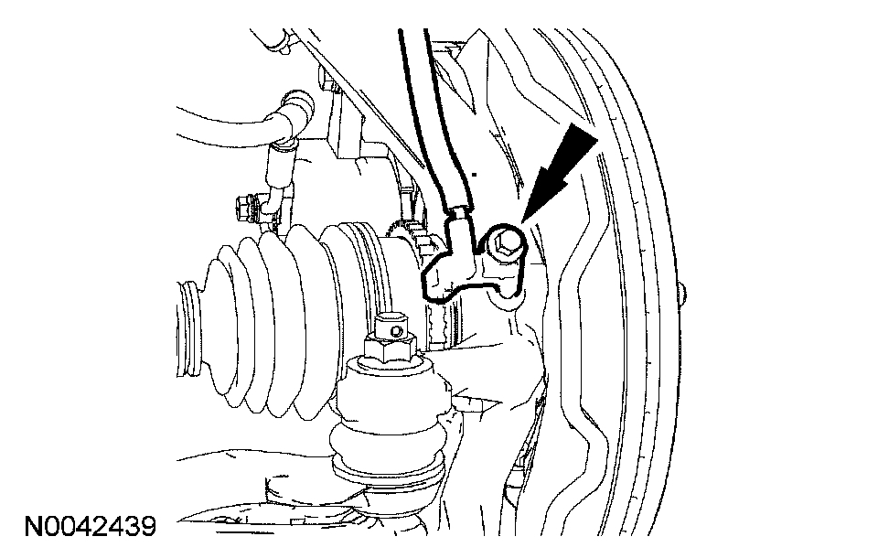
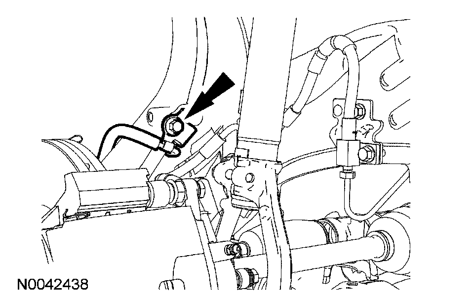
3. If equipped, remove the wheel speed sensor bolt.
4. If equipped, remove the wheel speed sensor harness bolt and position the wheel speed sensor aside.
5. Remove and discard the upper ball joint nut.
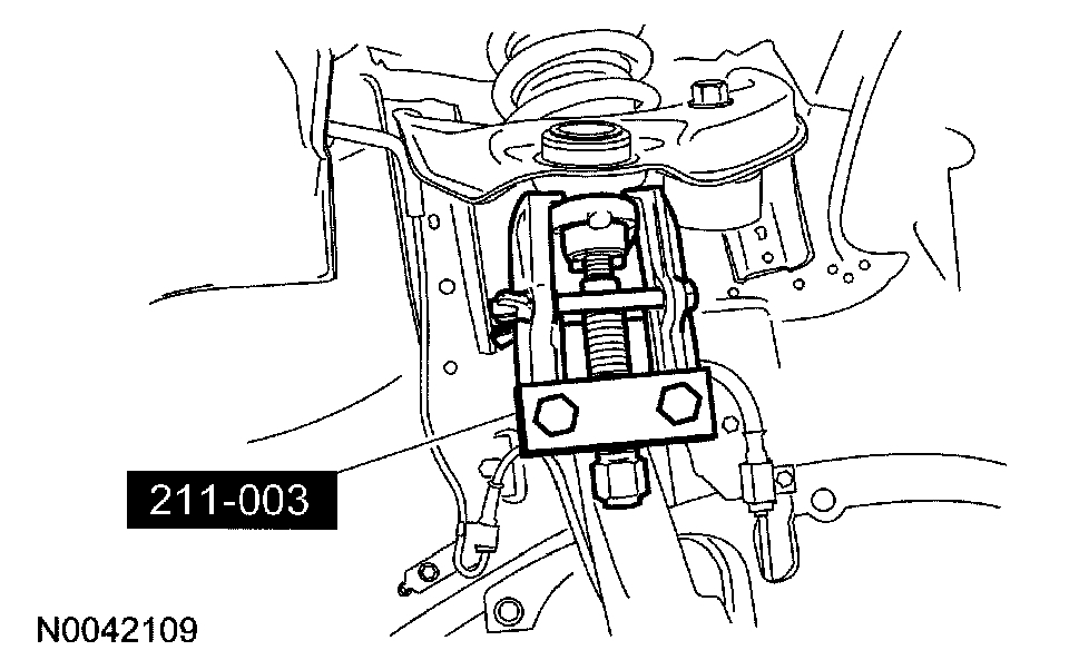
6. Using the special tool, separate the upper ball joint from the wheel knuckle.
7. Position the shock absorber and spring assembly toward the wheel knuckle to access the upper arm-to-body bolts.
8. Remove and discard the 2 upper arm-to-body bolts and remove the upper arm.
Installation
1. NOTE: Do not tighten the upper arm-to-body bolts at this time.
Position the upper arm and install new upper arm-to-body bolts.
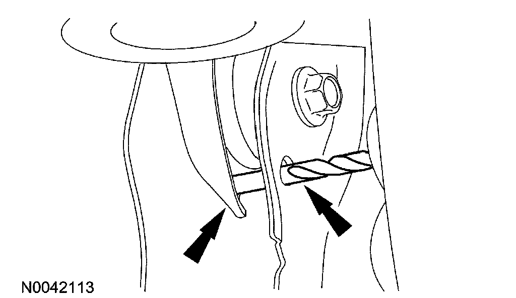
2. Set the upper arm bushing fastener tightening position by aligning the hole in the upper arm with the hole in the body bracket and inserting a 6.35 mm (0.25 inch) drill bit through both holes.
3. Tighten the upper arm-to-body bolts to 55 Nm (41 ft. lbs.) and remove the drill bit.
4. Position the shock and spring assembly and install new shock upper mount nuts.
^ Tighten to 30 Nm (22 ft. lbs.).
5. Connect the upper ball joint to the wheel knuckle and install a new upper ball joint nut.
^ Tighten to 48 Nm (35 ft. lbs.).
6. If removed, position the wheel speed sensor harness and install the bolt.
^ Tighten to 23 Nm (17 ft. lbs.).
7. If removed, position the wheel speed sensor and install the bolt.
^ Tighten to 23 Nm (17 ft. lbs.).
8. Check and, if necessary, align the front end.
______________________________
Next, here are the directions related to the tie rods. Note: The directions are more involved that what you most likely need. However, it does cover the torque specs.
_____________________________
PROCEDURES
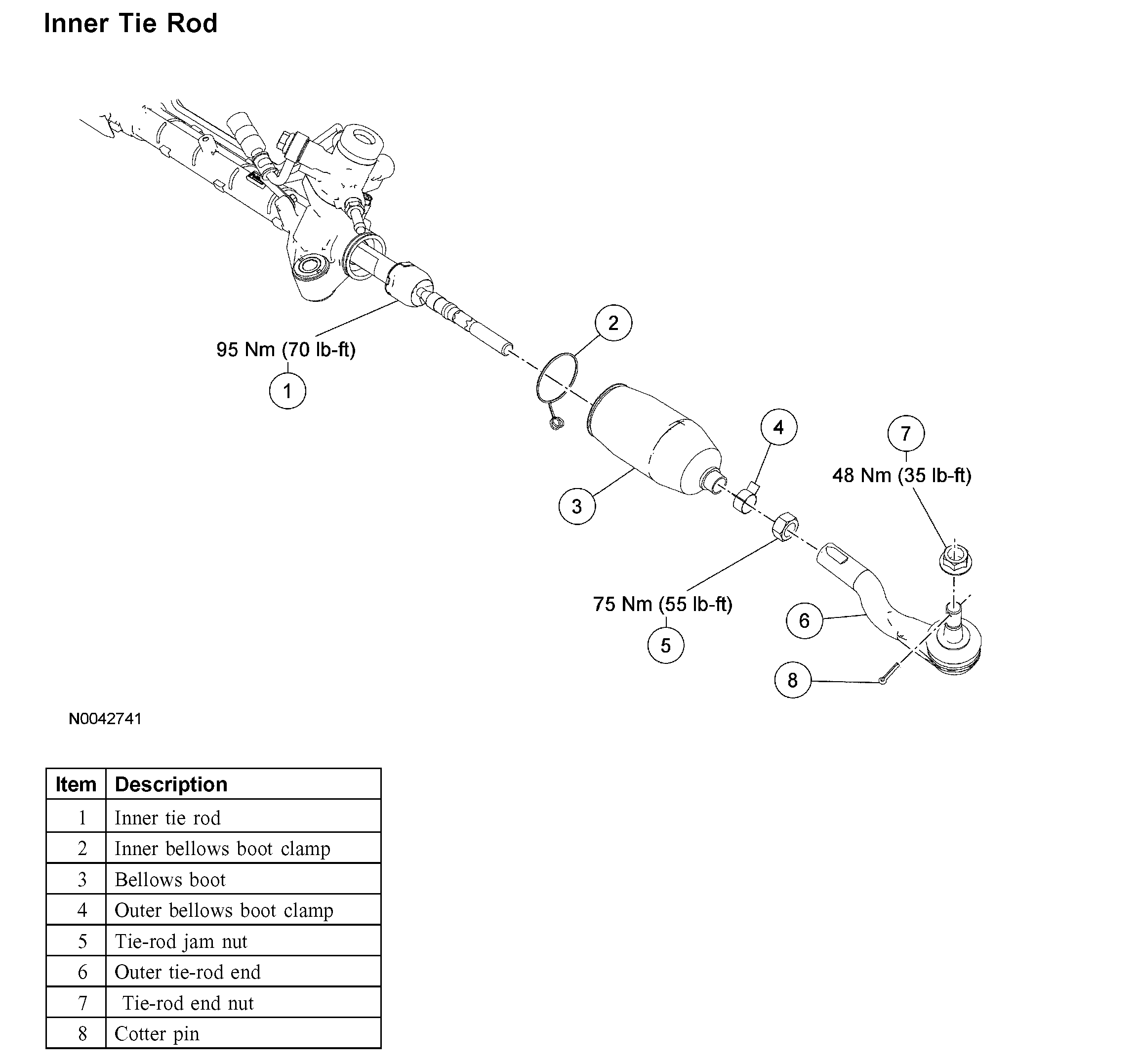
Inner Tie Rod
Inner Tie Rod
Removal and Installation
1. Remove the steering gear.
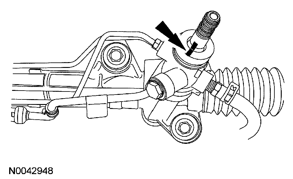
2. Mark the pinion shaft and the steering gear housing for proper reference during installation.
3. CAUTION: Position the steering gear in a soft jaw vise, or damage to the steering gear can occur.
Loosen the tie-rod end jam nut and remove the outer tie-rod end.
^ To install, tighten to 75 Nm (55 ft. lbs.).
4. NOTE: It is necessary to remove both bellows boots when removing the RH inner tie-rod end.
Remove the 4 bellow clamps and the 2 steering gear bellows boots.
5. Using a suitable wrench, hold the piston shaft.
6. Using a suitable wrench, remove the inner tie-rod end.
^ To install, tighten to 95 Nm (70 ft. lbs.).
7. NOTE: Using a suitable wrench, hold the piston shaft while tightening the inner tie-rod.
To install, reverse the removal procedure.
_______________________________
Now, I don't know if you needed specs for front or rear control arms. The directions above are for the front. Here are the directions for the rear. Note, the directions for the rear will start with the upper control arm and the lower will follow. Pictures starting with the eighth one will correlate with these directions.
______________________________
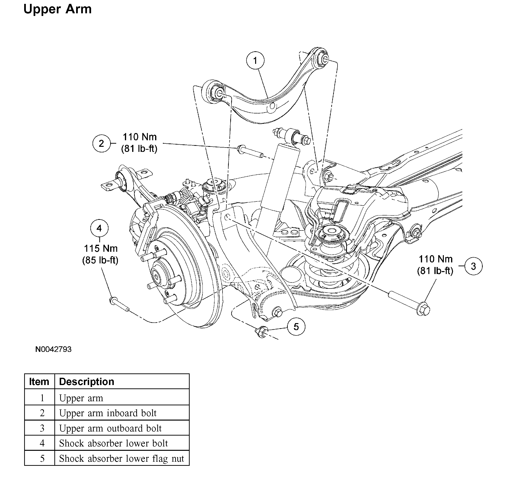
Upper Arm
Removal and Installation
CAUTION: Suspension fasteners are critical parts because they affect performance of vital parts and systems and their failure can result in major service expense. A new part with the same part number must be installed if installation becomes necessary. Do not use a replacement part of lesser quality or substitute design. Torque values must be used as specified during reassembly to make sure of correct retention of these parts.
1. With the vehicle in NEUTRAL, position it on a hoist. For additional information, refer to Maintenance/Service and Repair.
2. Remove and discard the shock absorber lower bolt and flag nut.
^ To install, tighten to 115 Nm (85 ft. lbs.) with the suspension at the bushing fastener tightening position.
3. Using a suitable jack, raise the trailing arm.
4. Remove and discard the upper arm outboard bolt.
^ To install, tighten to 110 Nm (81 ft. lbs.) with the suspension at the bushing fastener tightening position.
5. Carefully lower the trailing arm and remove the jack.
6. NOTE: Position the shock absorber as necessary to remove the upper arm.
Remove and discard the upper arm inboard bolt and remove the upper arm.
^ To install, tighten to 110 Nm (81 ft. lbs.) with the suspension at the bushing fastener tightening position.
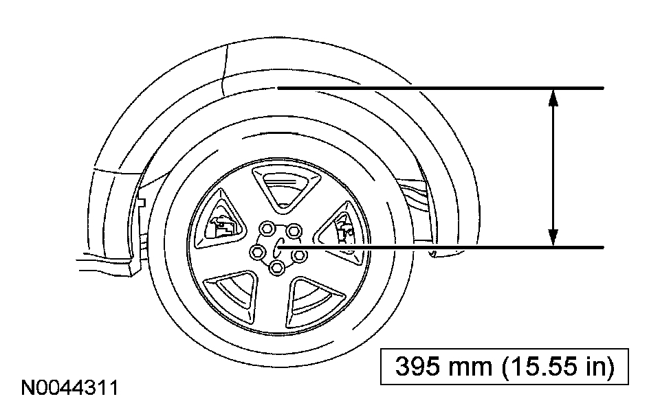
7. CAUTION: Before tightening any suspension bushing fasteners, the suspension must be at the bushing fastener tightening position. Use a suitable jack to raise the suspension until the distance between the center of the hub and the lip of the fender is equal to 395 mm (15.55 inch).
To install, reverse the removal procedure.
8. Check and, if necessary, adjust the rear camber.
__________________________________________________________
Lower
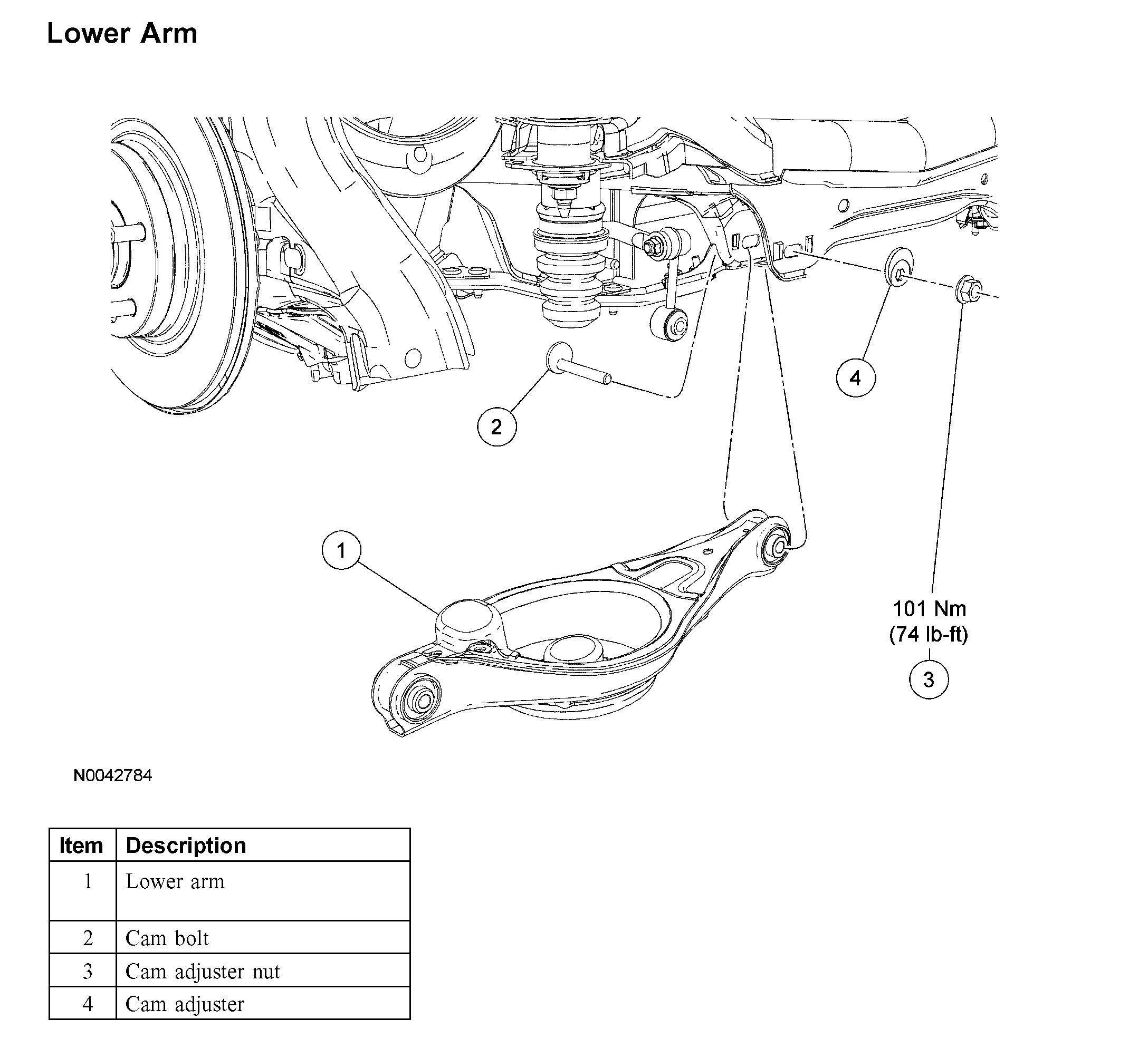
Lower Arm
Lower Arm
Removal and Installation
CAUTION: Suspension fasteners are critical parts because they affect performance of vital parts and systems and their failure can result in major service expense. A new part with the same part number must be installed if installation becomes necessary. Do not use a replacement part of lesser quality or substitute design. Torque values must be used as specified during reassembly to make sure of correct retention of these parts.
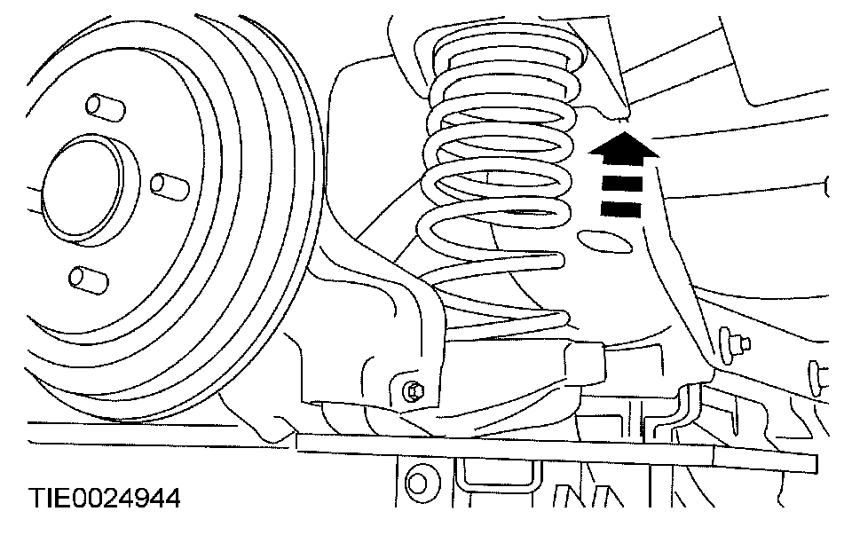
1. Remove the spring.
2. CAUTION: Do not fully tighten the cam adjuster nut until the rear alignment has been checked and, if necessary, adjusted.
Remove and discard the cam adjuster nut, then remove the cam adjuster, cam bolt and the lower arm.
^ To install, tighten to 101 Nm (74 ft. lbs.) with the suspension at the bushing fastener tightening position.
3. CAUTION: Before tightening any suspension bushing fasteners, the suspension must be at the bushing fastener tightening position. Use a suitable jack to raise the suspension until the distance between the center of the hub and the lip of the fender is equal to 395 mm (15.55 inch).
To install, reverse the removal procedure.
___________________________________________
Let me know if this is what you needed and if it helps.
Take care,
Joe
Images (Click to enlarge)
Dec 15, 2018 at 6:49 PM