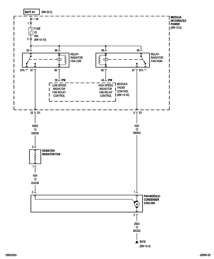
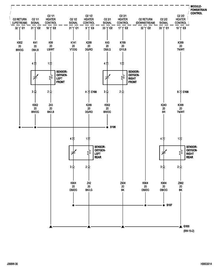
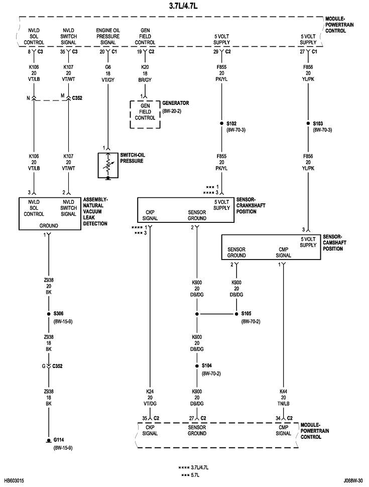
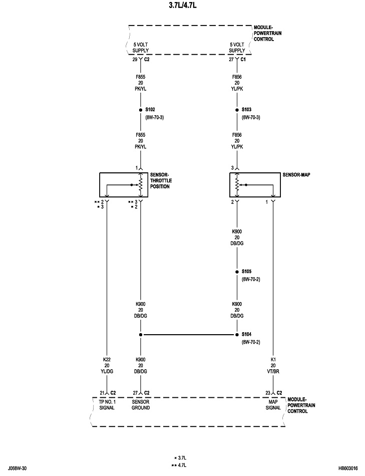
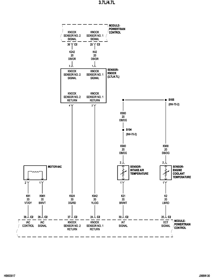
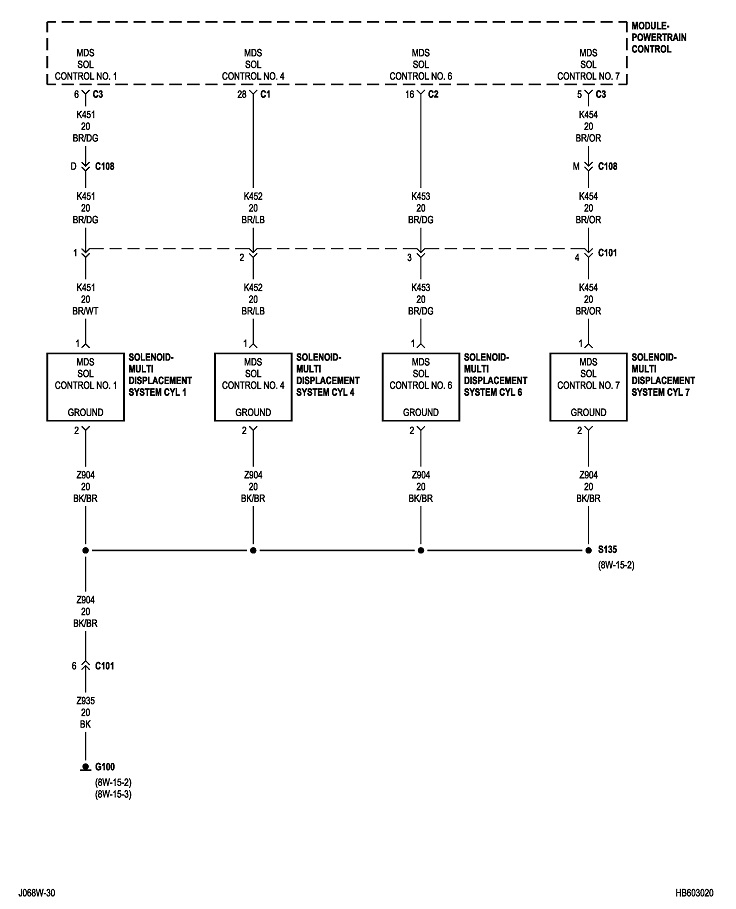
None of the sensors you listed are fed by the ASD relay. Those get a carefully regulated 5.0-volt supply from the Engine Computer. The most common things fed by the ASD relay include ignition coil(s), injectors, alternator field, oxygen sensor heaters, and the fuel pump or a separate fuel pump relay. First check if a wiring harness fell down onto hot exhaust parts. This is more common on a few car models, but it's something to not overlook.
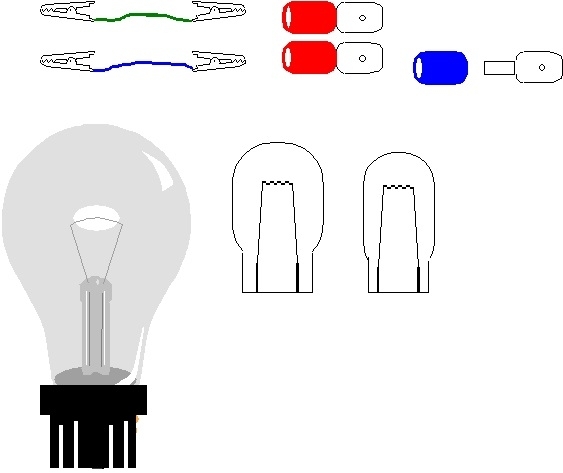
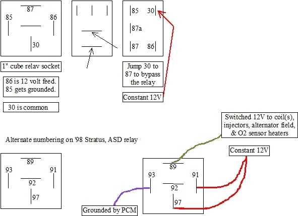
Next, there's a trick that will avoid the blowing fuses, but it lets you power up the circuit. That is to replace the fuse or the relay with a 12-volt light bulb. I prefer to replace the relay because that lets you work in the circuit without bothering to turn on the ignition switch. I made some drawings to simplify this for the benefit of others who aren't comfortable working with electronics.
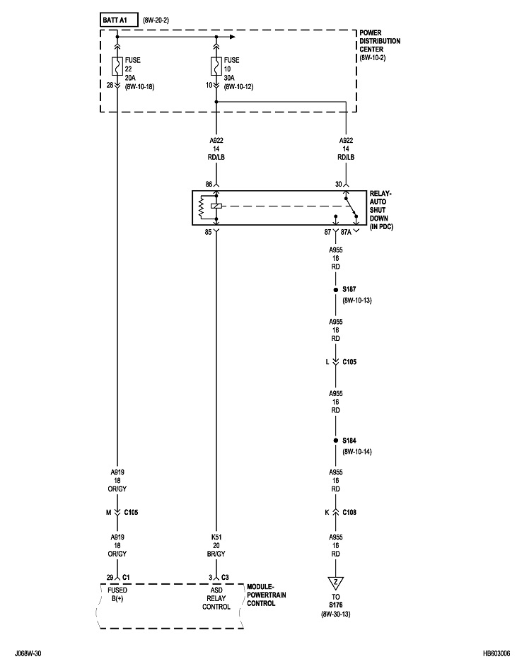
You also need to know when the ASD relay turns on. The Engine Computer does that for one second when you turn on the ignition switch, then it gets turned back off until the computer sees engine rotation, (cranking or running). It knows that by the signal pulses it receives from the crankshaft position sensor and the camshaft position sensor. What this means for troubleshooting is you can only do it while cranking the engine. That's not practical.
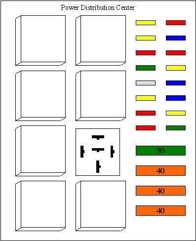
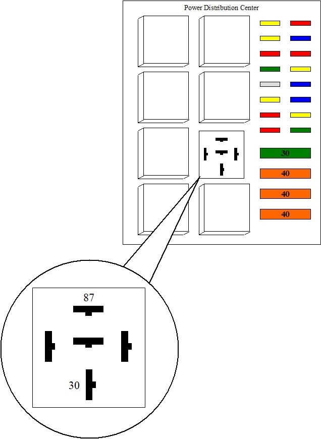
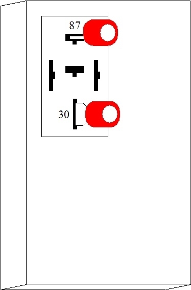
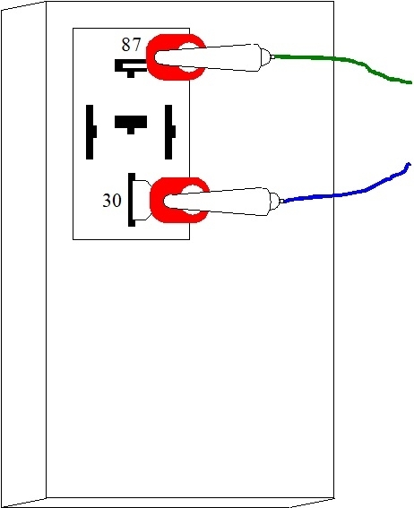
Remove the ASD relay, then stick in a pair of crimp-style universal spade terminals into terminals 30 and 87. Those correspond to the relay's contacts. You can use other things like paper clips, but be careful that whatever you stick in isn't fatter than the relay's terminals. A lot of future intermittent connections have been caused by spreading the terminals in the socket from inserting something too fat. For my own use, I soldered a Dodge Viper rear tail light harness to a blown fuse. The fuse is easy to insert, and the harness allows me to add from one to five separate bulb filaments, depending on how much current the circuit normally draws. An added advantage to that long harness is it can be hung over the rear-view mirror so it's easy to see from anywhere outside the vehicle.
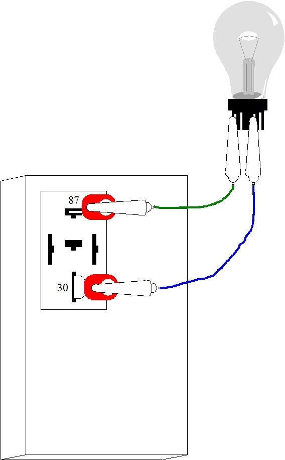
A common 3157 brake / tail light bulb works well in this circuit because it's easy to hook to small jumper wires. (You can find a pack of jumper wires at Harbor Freight Tools for just a few bucks). Connect the bulb to the two spade terminals in the fuse box. The bulb may become full brightness and very hot so place it away from anything that could burn or melt. Insert a good fuse.
With everything connected, the circuit will be powered up and try to operate. The bulb will do one of three things. If it stays fully off, a number of things have been disconnected, or the circuit is turned off. If it is dim, or at least less than full brightness, there is currently nothing shorted to ground, but current is flowing as it should. If it's full brightness, something is shorted to ground, which would equate to the blowing fuse.
The goal now is to get the bulb to full brightness so there is something to diagnose. When that happens, be careful to work gently in the circuit. Too many people just start tugging and banging to make the light go dim. At that point you have no idea what to look for. Instead, I start by gently moving the engine wiring harnesses around. If you see the brightness of the bulb flicker, you're in the right area. That would be typical of a harness melted on hot exhaust parts, or fallen down onto the sharp edge of a metal bracket and some wires have rubbed through.
When the bulb stays solidly bright, you're more likely to find a shorted component or a wire pinched tightly under a seat bracket, between two parts you were just working on, or in one case, a mud flap screw run through the harness. For solid shorts like that, unplug different things until the bulb suddenly goes dim. There's usually a large connector between the engine harness and the body. That's a good place to start. If the bulb stays bright, leave that connector apart and move on. If the bulb went dim, reconnect that connector, then try to narrow it down by unplugging smaller connectors further down the line. I've never run into a shorted injector or ignition coil, but you might find a problem with the wires going to them.
When the test bulb starts out dim, it is common to have a short that only occurs while driving, especially over bumpy roads. For that, walk around the vehicle with a rubber hammer. I found one that way where the owner installed a new trailer wiring harness on a full-size van. The tail light wire got caught under the corner of the left rear tail light lens and caused the short to occur when I tapped it very lightly. The test bulb would flicker bright and dim.
By the way, the test bulb limits current to a safe level when the short is present. If you connect the jumper wires to both filaments in a 3157 bulb, the bright one, (brake / signal) will pass one amp. The dim one, (tail light), will pass roughly 3/4 amp, so the two together will allow just under two amps to flow. When the short is removed, the circuit will try to operate, and usually two amps isn't enough. You might try using a 9004 head light bulb instead. The low-beam filament will pass up to five amps. The high-beam is good for closer to six amps. I used a head light bulb on that van I mentioned. When the short was gone, the van's tail and running lights started to glow just enough that I could see them with close inspection. That told me everything else was working properly. The reason the tail lights were dim is you only have 12 volts from the battery to start with. Some of that, let's say seven volts, is "dropped" by the head light / test bulb. That leaves just five volts to run the tail lights.
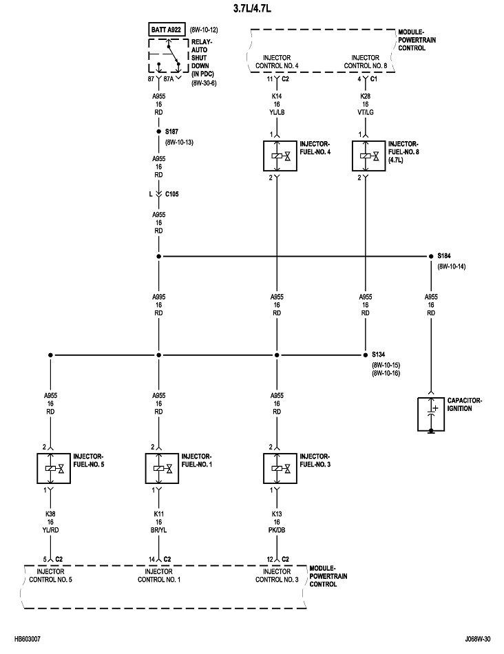
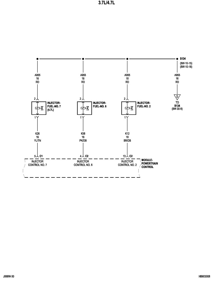
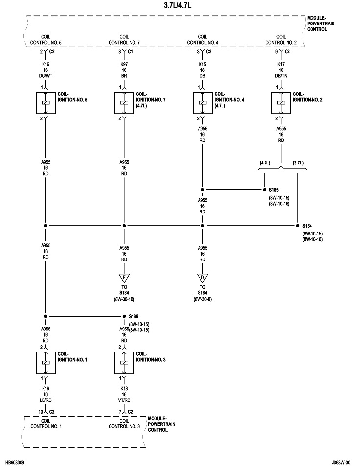
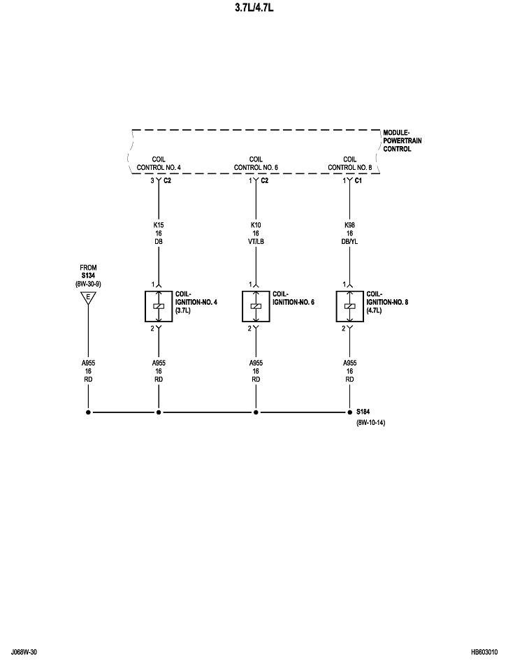
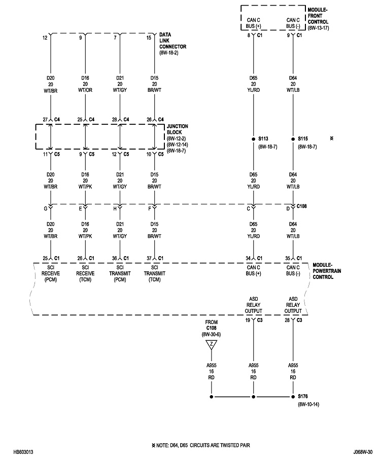
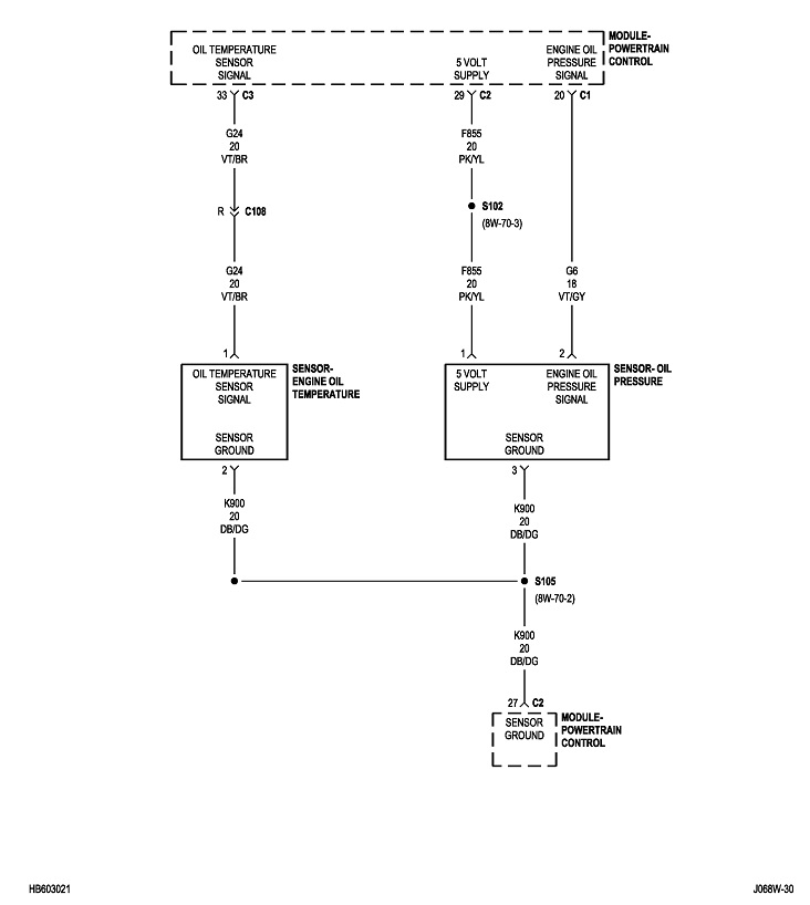
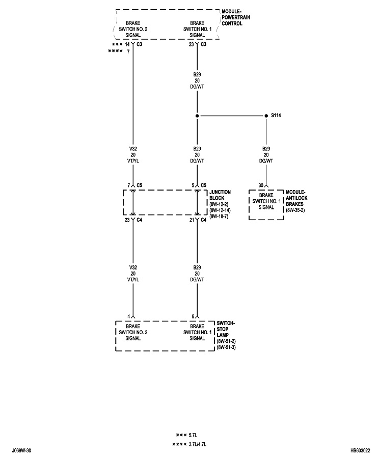
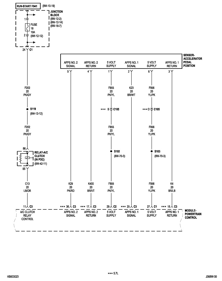
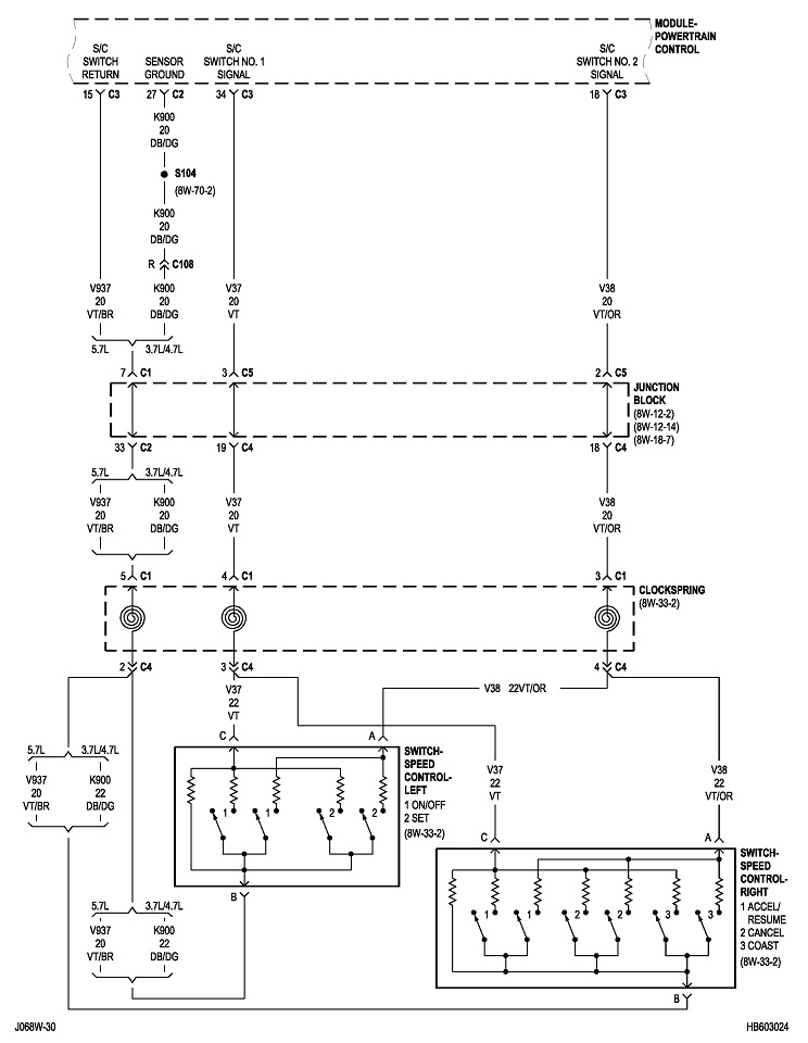
You can do this same procedure by replacing the fuse with the test bulb. For example, large 30-amp fuses often feed multiple smaller fuses that each protect their own circuits. When you get the short to occur, remove each smaller fuse, one at a time, until the short goes away. Once you identify that fuse, put the test bulb in place of that one, then continue on the same way. It can help to know what is on a fuse's circuit so you know what to unplug or inspect. I'll post the diagrams for "Powertrain Management" later. It will take some time to format them for uploading.
Images (Click to enlarge)
Sep 8, 2025 at 3:36 PM