Welcome to 2CarPros.
Step one in the directions for mode door actuator replacement is to remove the IP carrier. Basically, that means remove the dash. As far as a short cut, I don't know of any. I wish I did.
___________________________________
Here are the directions for the IP carrier. The directions are listed as removal and replacement of the instrument panel. The attached pictures correlate with the directions. I will also include the directions for replacing the actuator. That will be second.
_________________________________
2002 Cadillac DeVille V8-4.6L VIN Y
Instrument Panel (IP) - Assembly Replacement
Vehicle Body and Frame Interior Moulding / Trim Dashboard / Instrument Panel Service and Repair Removal and Replacement Instrument Panel (IP) - Assembly Replacement
INSTRUMENT PANEL (IP) - ASSEMBLY REPLACEMENT
IP Assembly Replacement
Removal Procedure
Caution: Refer toSIR Caution in Cautions and Notices.
1. Disable SIR. Refer to Disabling the SIR System in SIR.
2. Remove the left knee bolster. Refer to Knee Bolster Replacement - Left (Without UV2) (See: Knee Diverter > Procedures > Knee Bolster Replacement - Left (Without RPO UV2))Knee Bolster Replacement - Left (UV2) (See: Knee Diverter > Procedures > Knee Bolster Replacement - Left (With RPO UV2)).
3. Remove the left knee bolster support. Refer to Knee Bolster Bracket Replacement - Left (See: Knee Diverter > Procedures > Knee Bolster Bracket Replacement - Left).
4. Remove the right knee bolster. Refer to Knee Bolster Replacement - Right (See: Knee Diverter > Procedures > Knee Bolster Replacement - Right).
5. Remove the IP center seat or the floor console. Refer to Compartment Replacement - IP (Base and DHS) (See: Glove Compartment > Removal and Replacement > Instrument Panel Compartment - Replacement (Base and DHS))Compartment Replacement - IP (DTS) (See: Glove Compartment > Removal and Replacement > Instrument Panel Compartment - Replacement (DTS)) in Seats, or Console Replacement - Front Floor (DTS, w/o UV8) (See: Console > Removal and Replacement > Console Replacement - Front Floor (DTS Without RPO UV8))Console Replacement - Front Floor (DTS with UV8) (See: Console > Removal and Replacement > Console Replacement - Front Floor (DTS With RPO UV8)).
6. Remove the IP outer trim panels. Refer to Instrument Panel (IP) Outer Trim Cover Replacement - Right (See: Dashboard / Instrument Panel > Removal and Replacement > Instrument Panel (IP) - Outer Trim Cover Replacement - Right) and Instrument Panel (IP) Outer Trim Cover Replacement - Left (See: Dashboard / Instrument Panel > Removal and Replacement > Instrument Panel (IP) - Outer Trim Cover Replacement - Left).
7. Remove the windshield pillar trim. Refer to Garnish Molding Replacement - Windshield Pillar (See: Trim Panel > Removal and Replacement > Garnish Molding Replacement - Windshield Pillar) in Interior Trim.
8. Remove the defroster grille. Refer to Defroster Grille Replacement (Without UV2) (See: Air Register > Removal and Replacement > Defroster Grille Replacement (Without UV2))Defroster Grille Replacement (UV2) (See: Air Register > Removal and Replacement > Defroster Grille Replacement (UV2)).
9. Remove the IP upper trim pad. Refer to Trim Pad Replacement - IP Upper (See: Dashboard / Instrument Panel > Removal and Replacement).
10. Remove the heads up display, if equipped with UV8. Refer to Head Up Display Module Replacement See: Heads Up Display Unit > Procedures
pic 1
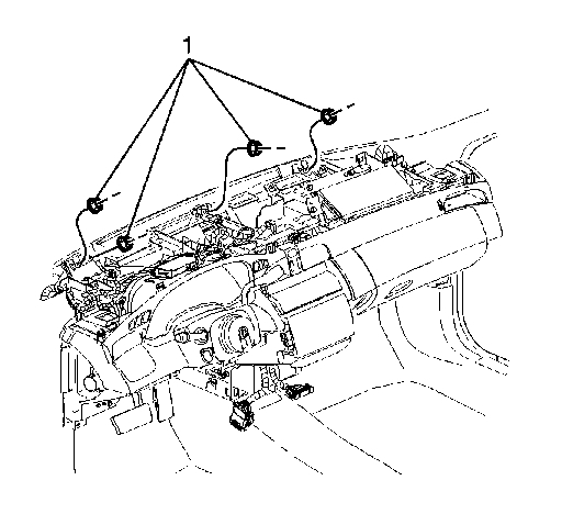
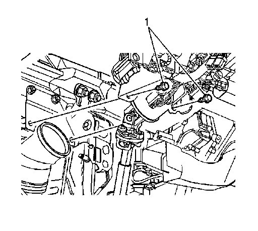
11. Disconnect the body to IP electrical connectors (1) at the top, outside corners of IP.
12. Disconnect all other electrical connectors from the IP to body.
13. Disconnect the steering column shaft from the steering column.
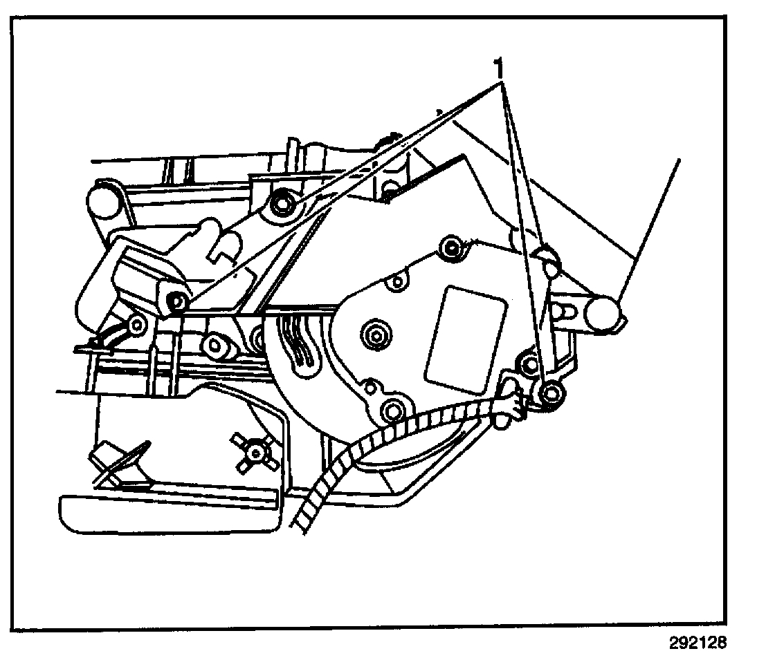
Pic 2
14. Remove the steering column to body bolts (1). Refer to Steering Column Replacement (Floor Shift) Steering Column Replacement (Column Shift) in Steering Wheel and Column.
15. For a DeVille base model, or the DeVille DHS, disconnect the shift cable from the steering column.
16. Disconnect the Steering column to body connectors.
Pic 3
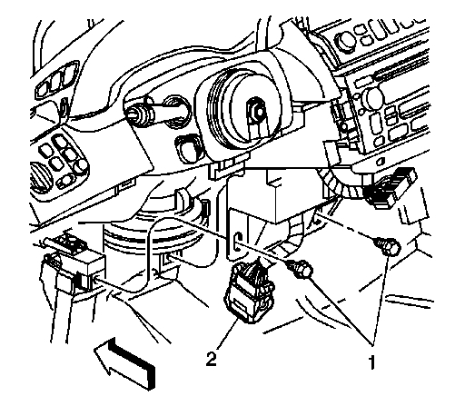
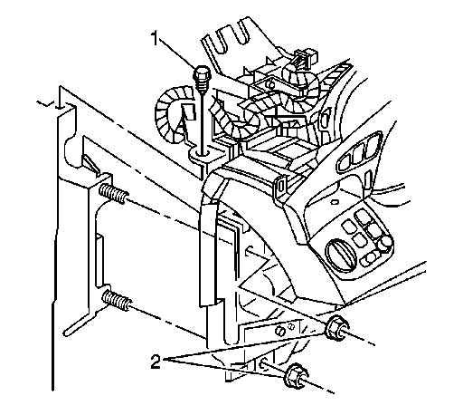
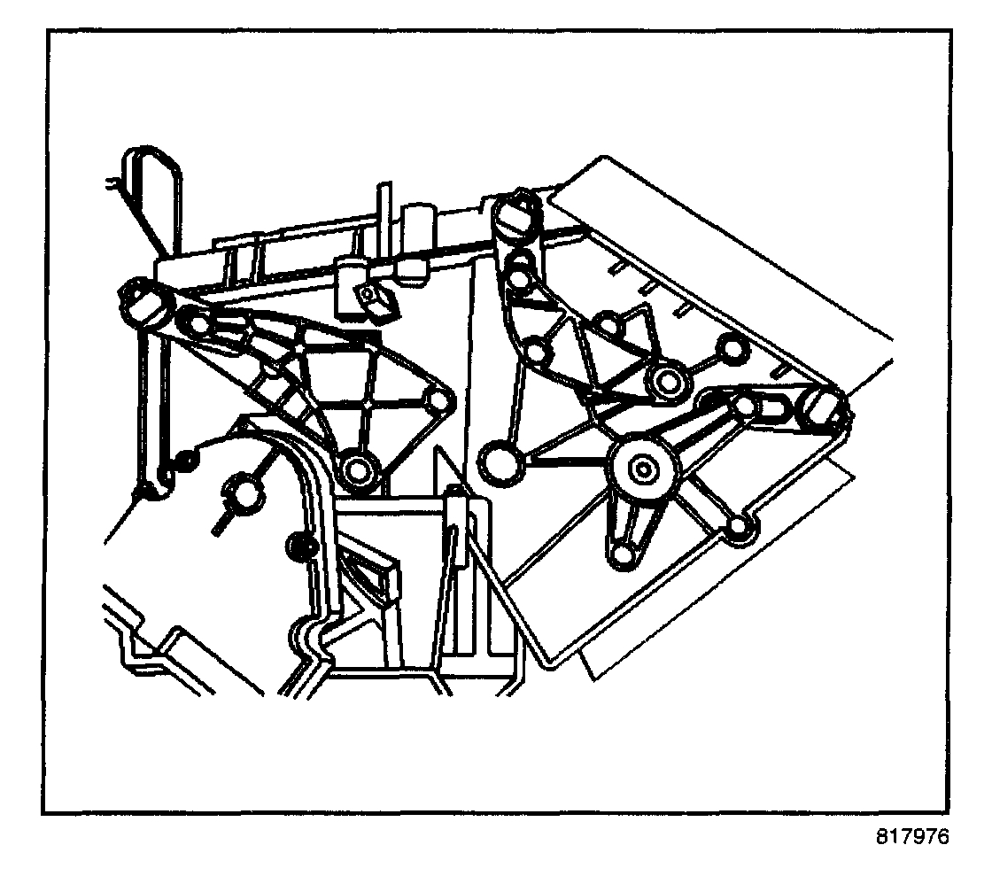
17. Remove the IP center support bracket bolts (1) to floor bracket.
Pic 4
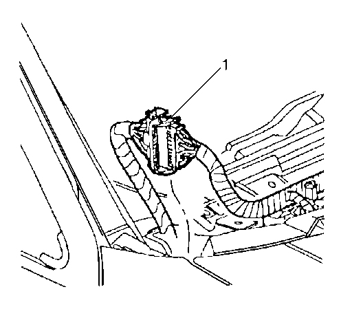
18. Remove IP carrier (1) to cowl nuts.
Pic 5
19. Remove the bolt (1) and nuts (2) from the left and right IP carrier to hinge pillar.
Pic 6
20. Remove the IP and carrier assembly from the vehicle.
Installation Procedure
pic 7
1. Install the IP and carrier assembly to the vehicle.
Pic 8
Notice: Refer to Fastener Notice in Cautions and Notices.
2. Install the nuts and bolts (1, 2) to the IP carrier.
Tighten the IP carrier nuts and bolts to 25 N.M (18 lb ft).
Pic 9
3. Install the IP carrier to cowl nuts (1).
Tighten the IP carrier to cowl nuts to 25 N.M (18 lb ft).
Pic 10
4. Install the IP center support bracket bolts (1) to floor bracket.
Tighten the IP center support bracket bolts to 25 N.M (18 lb ft).
Pic 11
5. Install the steering column bolts (1). Refer to Steering Column Replacement (Floor Shift) Steering Column Replacement (Column Shift) in Steering Wheel and Column.
6. For a DeVille base model, or the DeVille DHS, Install the shift cable to the steering column.
7. Connect Steering column to body electrical connectors.
8. Connect the IP to body electrical connectors (1) at top outside corners of IP.
9. Install the heads up display, if equipped with UV8. Refer to Head Up Display Module Replacement See: Heads Up Display Unit > Procedures
10. Install the IP upper trim pad. Refer to Trim Pad Replacement - IP Upper (See: Dashboard / Instrument Panel > Removal and Replacement).
11. Install the defroster grille. Refer to Defroster Grille Replacement (Without UV2) (See: Air Register > Removal and Replacement > Defroster Grille Replacement (Without UV2))Defroster Grille Replacement (UV2) (See: Air Register > Removal and Replacement > Defroster Grille Replacement (UV2)).
12. Install the windshield pillar trim. Refer to Garnish Molding Replacement - Windshield Pillar (See: Trim Panel > Removal and Replacement > Garnish Molding Replacement - Windshield Pillar) in Interior Trim.
13. Install the center seat or the center console. Refer to Compartment Replacement - IP (Base and DHS) (See: Glove Compartment > Removal and Replacement > Instrument Panel Compartment - Replacement (Base and DHS))Compartment Replacement - IP (DTS) (See: Glove Compartment > Removal and Replacement > Instrument Panel Compartment - Replacement (DTS)) in Seats, or Console Replacement - Front Floor (DTS, w/o UV8) (See: Console > Removal and Replacement > Console Replacement - Front Floor (DTS Without RPO UV8))Console Replacement - Front Floor (DTS with UV8) (See: Console > Removal and Replacement > Console Replacement - Front Floor (DTS With RPO UV8)).
14. Install the left and right IP outer trim panels. Refer to Instrument Panel (IP) Outer Trim Cover Replacement - Right (See: Dashboard / Instrument Panel > Removal and Replacement > Instrument Panel (IP) - Outer Trim Cover Replacement - Right) and Instrument Panel (IP) Outer Trim Cover Replacement - Left (See: Dashboard / Instrument Panel > Removal and Replacement > Instrument Panel (IP) - Outer Trim Cover Replacement - Left).
15. Install the left knee bolster support bracket. Refer to Knee Bolster Bracket Replacement - Left (See: Knee Diverter > Procedures > Knee Bolster Bracket Replacement - Left).
16. Install the left knee bolster. Refer to Knee Bolster Replacement - Left (Without UV2) (See: Knee Diverter > Procedures > Knee Bolster Replacement - Left (Without RPO UV2))Knee Bolster Replacement - Left (UV2) (See: Knee Diverter > Procedures > Knee Bolster Replacement - Left (With RPO UV2)).
17. Install the right knee bolster. Refer to Knee Bolster Replacement - Right (See: Knee Diverter > Procedures > Knee Bolster Replacement - Right).
18. Enable the SIR. Refer to Enabling the SIR System in SIR.
___________________________________
2002 Cadillac DeVille V8-4.6L VIN Y
Mode Actuator Replacement
Vehicle Heating and Air Conditioning Air Door Actuator / Motor Service and Repair Procedures HVAC System - Automatic Mode Actuator Replacement
MODE ACTUATOR REPLACEMENT
REMOVAL PROCEDURE
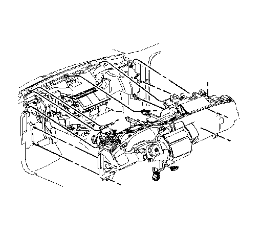
pic 12
1. Remove the IP carrier.
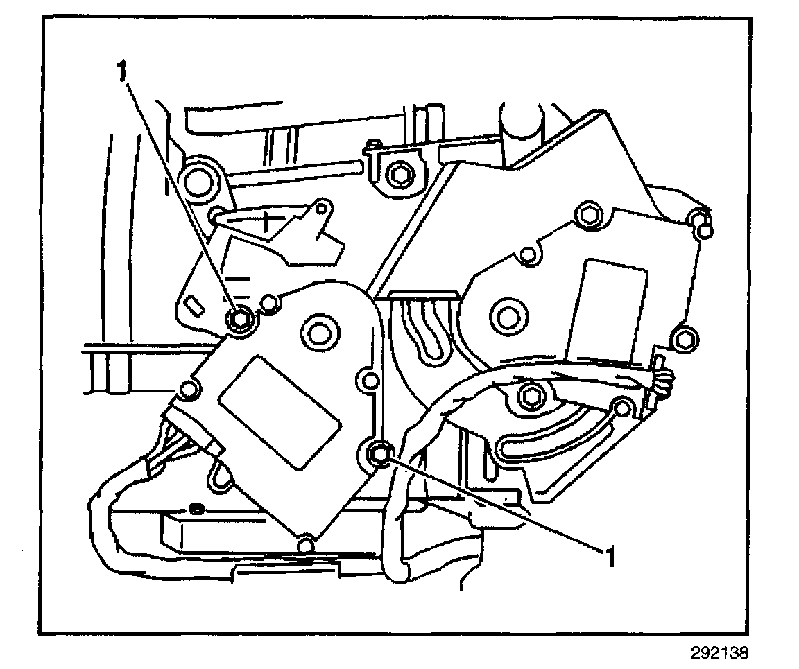
IMPORTANT: The left air temperature actuator does not need to be removed in order to remove the mode actuator motor.
The left air temperature actuator is removed in the graphic in order to show the screw locations.
2. Remove the mode actuator retaining screws (1).
3. Remove the mode actuator.
Pic 13
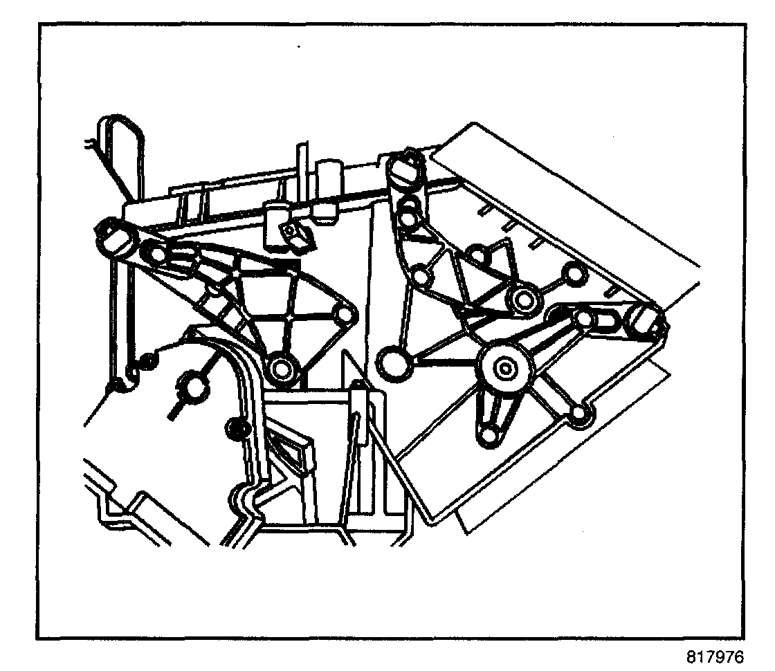
4. Note the position of the door levers to the cam. The mode door levers must be in the same position in order to reassemble the mode actuator to the HVAC case.
INSTALLATION PROCEDURE
pic 14
1. The mode door levers must be in the this position in order to reassemble the mode actuator to the HVAC case.
Pic 15
2. Lubricate the pivots on the mode door levers and the channels on the mode motor cam before reassembling.
3. Align the mode door levers with the cam slots, as noted on disassembly.
4. Install the mode actuator to the HVAC module.
NOTE: Refer to Fastener Notice in Service Precautions.
5. Install the mode actuator retaining screws (1).
Tighten
Tighten the screws to 1.4 N.M (12 lb in).
6. Install the IP carrier.
______________________________________________
I hope this helps. Let me know if you have other questions.
Take care,
Joe
Images (Click to make bigger)
Saturday, September 14th, 2019 AT 9:14 PM