Hello -
Okay my friend, let's see if we can get you some assistance here.
The tune up.......I didn't see where you changed the plugs. According to the maintenance table plugs should be changed every 35,000 miles. So I would change those for sure. They were due at 70,000.
Next, the fuel filter is to be changed at 100,000 miles. Well, you are at 98K now so I would change that too.
Now for the rest.
I reviewed the TSBs and there is actually one for P2070 and the fix for it. I have attached that for your review.
Next, there are two other TSBs I attached for your review that deal with lack of power. If you want the figures for them let me know and I will take the time to load them. I will first give you the TSBs to review. I figured since 2070 was the code and I wasn't sure about the plugs and filter, do that first.
Your thoughts?
MIL ON - P2070 SET
TECHNICAL SERVICE BULLETIN
Reference Number(s): 01-019/08, Date of Issue: 4/18/2008
MAZDA: 2004-2007 RX-8 vehicles
Superceded Bulletin(s): 01-019/08, Date of Issue: 3/21/2008
Related Ref Number(s): 01-019/08
ARTICLE BEGINNING
BULLETIN NOTE
NOTE: This bulletin supersedes the previous bulletin 01-019/08, issued 3/21/2008. The WARRANTY INFORMATION has been revised.
APPLICABLE MODEL(S)/VINS
2004-2007 RX-8 vehicles with VINs lower than JM1 FE**** ** 213322 (built before April 18, 2007)
DESCRIPTION
Some vehicles may experience a MIL with DTC P2070 (SSV Stuck Open). This may be caused by carbon build up near the SSV bushing, which may cause driveability concerns (hesitation and / or lack of power) and / or DTC P2070. A cleaning procedure and a revised SSV with stronger actuator force is now available.
Customers having this concern should have their vehicle repaired using the following repair procedure.
REPAIR PROCEDURE
1. Verify the following:
o P2070 is set.
o SSV sticks without failure of SSV solenoid valve switch.
2. Record freeze frame data.
3. Record customer radio station presets.
4. Disconnect negative battery cable.
5. Raise and support vehicle.
6. Drain engine coolant into a clean container for reuse after repair. Refer to Workshop Manual section 01-12 ENGINE COOLANT REPLACEMENT.
7. Remove right front wheel.
8. Remove rubber splash shield from inner fender to access right side of engine.
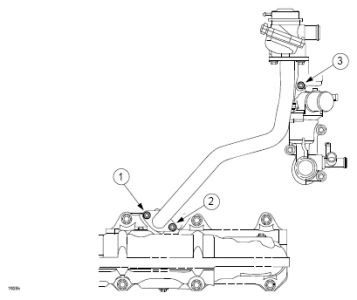
9. Remove 2 nuts (1) attaching air pipe (2) to exhaust manifold (3).
Fig. 1: Locating Nuts Attaching Air Pipe To Exhaust Manifold
Courtesy of MAZDA MOTORS CORP.
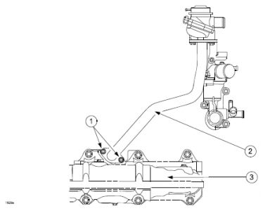
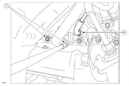
10. Disconnect port air bleed vacuum hose (4) from intake manifold.
Fig. 2: Locating Port Air Bleed Vacuum Hose
Courtesy of MAZDA MOTORS CORP.
11. Lower vehicle.
12. Remove battery cover, battery and battery tray to make work space. Refer to Workshop Manual section 01- 17 BATTERY REMOVAL / INSTALLATION.
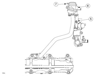
13. Remove air control valve bracket bolt (5).
Fig. 3: Locating Air Control Valve Bracket Bolt
Courtesy of MAZDA MOTORS CORP.
14. Disconnect main harness from air control valve bracket.
15. Disconnect upper hose (6) and vacuum line (7) from air control valve.
16. Position air control valve and air pipe out of the way by moving toward washer fluid reservoir.
17. Loose 3 water pump pulley bolts (8) but do not remove.
Fig. 4: Identifying Water Pump Pulley Bolts & Torque Specifications
Courtesy of MAZDA MOTORS CORP.
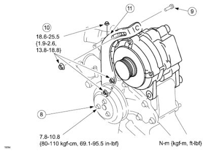
18. Loosen alternator belt tension bolt and remove attaching bolt and nut (9) from alternator and bracket.
19. Remove alternator belt.
20. Remove water pump pulley.
21. Remove 3 nuts (10) and alternator bracket (11).
22. Raise and support vehicle.
23. Remove 2 bolts (12) attaching port air bleed vacuum pipe.
Fig. 5: Locating Bolts Attaching Port Air Bleed Vacuum Pipe
Courtesy of MAZDA MOTORS CORP.
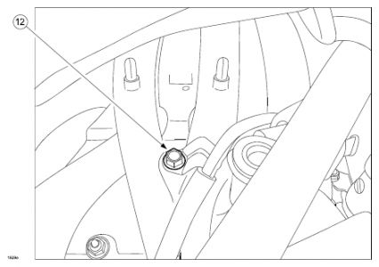
Fig. 6: Locating Lower Nuts On Thermostat Housing
Courtesy of MAZDA MOTORS CORP.
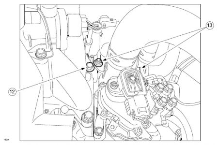
24. Remove 2 lower nuts (13) on thermostat housing.
25. Lower vehicle.
26. Remove 1 upper nut on thermostat housing.
27. Carefully position oil metering lines and bracket away from upper thermostat housing stud as to be able to remove thermostat housing from mounting studs.
28. Remove thermostat housing from mounting studs and position toward front of vehicle to allow access to SSV.
29. Position main harness to the side to allow access to SSV.
30. Disconnect SSV switch connector (14).
Fig. 7: Locating SSV Switch Connector
Courtesy of MAZDA MOTORS CORP.
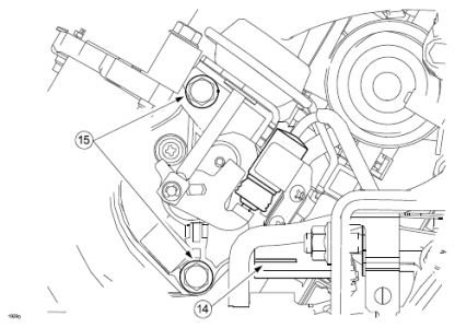
31. Remove 2 bolts (15) attaching SSV.
NOTE: "¢ The upper SSV bolt will not be reused for assembly. A longer bolt is provided.
32. Pull out SSV using a slow twisting motion.
NOTE: "¢ Ensure sufficient working space is available to access the SSV port in the next steps.
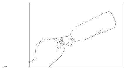
33. Wrap a shop towel around the handle of a screwdriver (or equivalent) and use a zip-tie to secure the towel at the handle end.
NOTE: "¢ Ensure the screwdriver handle (or equivalent) is as close to 1/2" (12mm) as possible.
Fig. 8: Wrapping Shop Towel Around Handle Of Screwdriver
Courtesy of MAZDA MOTORS CORP.
34. Place a rag in SSV port of intake manifold to catch carbon deposits (debris).
NOTE: "¢ A shop rag may need to be cut in half to fit properly to allow access to the bushing at the rear of the port.
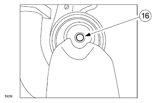
35. Hold engine cleaner up-right and spray inside the SSV port, focusing on the bushing (16) located at the rear of the port.
WARNING: "¢ PLEASE USE CAUTION WHEN USING ENGINE CLEANER.
"¢ WEAR EYE PROTECTION AND GLOVES WHEN HANDLING.
"¢ ENGINE CLEANER IS FLAMMABLE.
NOTE: "¢ 1 can of engine cleaner is sufficient for 2 engine cleanings.
Fig. 9: Locating Bushing At Rear Of Port
Courtesy of MAZDA MOTORS CORP.
37. Wait five (5) minutes after spraying.
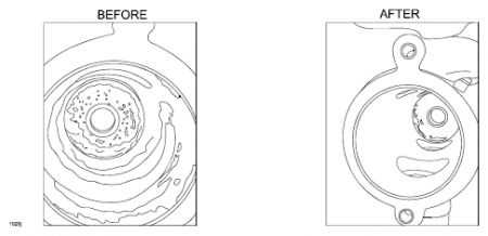
38. Using screwdriver with rag wrapped around the end, clean inner surface of SSV port.
CAUTION: "¢ Use care to restrict the amount of carbon debris that falls into the intake manifold ports.
Fig. 10: View Of Inner Surface Of SSV Port
Courtesy of MAZDA MOTORS CORP.
39. Install modified SSV and gasket. Install modified longer bolt (9979-60-640) in the upper mounting hole.
40. Assemble in the reverse order of removal.
IMPORTANT: "¢ Follow the tightening procedure below when installing air pipe and air control valve.
"¢ Hand-tighten nuts (1, 2) first then hand-tighten bolt (3). Tighten nuts (1, 2 then 3) to 69.1- 95.5 in-lbf. (7.8-10.8 Nm).
Fig. 11: Locating Air Pipe Nuts And Air Control Valve Bolt
Courtesy of MAZDA MOTORS CORP.
41. Connect negative battery cable.
42. Fill engine coolant system using coolant removed from engine and purge air out of the cooling system. Refer to Workshop Manual section 01-12 ENGINE COOLANT REPLACEMENT.
43. Check SSV function. Refer to workshop manual section 01-03 - SECONDARY SHUTTER VALVE (SSV) OPERATION INSPECTION.
44. Set recorded customer radio station presets.
45. Set clock.
46. In equipped with DSC, perform steering angle sensor initialization procedure. Refer to Workshop Manual section 04-15 - STEERING ANGLE SENSOR INITIALIZATION PROCEDURE.
47. Verify repair.
PART(S) INFORMATION
PARTS INFORMATION
Part Number Description Qty. Notes
N3H5-20-160F Valve, Shutter-Manifold (SSV) 1 -
N3H4-20-155A Gasket, SSV 1 -
9979-60-640 Bolt 1 Longer upper SSV bolt
N3H1-13-996 Gasket, ACV 1 -
0000-77-A86 Engine Cleaner 1 Quantity 1 = 1 can of engine cleaner when ordered through eMDCS.
1 can of engine cleaner is sufficient for 2 engine cleanings.
WARRANTY INFORMATION
NOTE: "¢ This warranty information applies only to verified customer complaints on vehicles eligible for warranty repair.
"¢ This repair will be covered under Mazda's New Vehicle Limited Warranty term.
"¢ Additional diagnostic time cannot be claimed for this repair.
WARRANTY INFORMATION
Warranty Type A
Symptom Code 6X
Damage Code 93
Part Number Main Cause N3H5-20-160F
Quantity 1
Related Part Number
"¢ Reimbursement Engine cleaner 5555-08-008A
Allowance applies to 1/2 can of engine cleaner per repair
Related Part Number Quantity 1
Operation Number / Labor Hours: XXC31XRX / 1.6 Hrs
Next TSB
MAZDA SPECIAL PROGRAM (MSP16) - ENGINE LACK OF POWER - PCM REFLASH
TECHNICAL SERVICE BULLETIN
Reference Number(s): 01-013/08, Date of Issue: 4/18/2008
MAZDA: 2004-2008 RX-8 vehicles
Superceded Bulletin(s): 01-013/08, Date of Issue: 3/14/2008
Related Ref Number(s): 01-013/08
ARTICLE BEGINNING
BULLETIN NOTE
NOTE: This bulletin supersedes the previous bulletin 01-013/08, issued 3/14/2008. The WARRANTY INFORMATION has been revised.
APPLICABLE MODEL(S)/VINS
2004-2008 RX-8 vehicles, produced from April 10, 2003 through November 9, 2007
"¢ VIN Range: JM1 FE17** 40100053 - 80215462
DESCRIPTION
Some 2004-2008 RX-8 vehicles may experience a lack of engine power and/or low/rough engine idle speed in high ambient temperatures. A revised PCM calibration is available which increases metering oil lubrication amount during engine start and changes ignition timing control during high ambient air temperature conditions.
NOTE: "¢ UNDER THE MAZDA SPECIAL PROGRAM (MSP16), ALL CURRENT DEALER INVENTORY AND RETAILED VEHICLES FOUND TO BE WITHIN THE ABOVE VIN RANGE, AND PRODUCED BETWEEN APR. 10, 2003 THROUGH NOV. 9, 2007, MUST BE INSPECTED AND REPAIRED ACCORDING TO THE INSTRUCTIONS CONTAINED IN THIS SERVICE BULLETIN.
"¢ BEFORE PERFORMING ANY REPAIR, VALIDATE THAT THE VEHICLE IS APPLICABLE TO THIS PROGRAM BY PERFORMING AN "eMDCS WARRANTY VEHICLE INQUIRY" AND VERIFYING THE VEHICLE DISPLAYS CAMPAIGN "MSP16" AND ITS CAMPAIGN STATUS DISPLAYS "OPEN". SEE "VEHICLE INSPECTION PROCEDURE" BELOW.
DEALER INVENTORY:
Inspect and repair if necessary, all applicable vehicles currently in dealer inventory according to the procedures contained in this service bulletin.
RETAIL VEHICLES:
When an applicable retail vehicle is brought into the dealer for any type of repair or scheduled maintenance, perform an eMDCS Warranty Vehicle Inspection and check the status of MSP16. If status of MSP16 is "OPEN" inspect and repair if necessary, the vehicle according to the procedures contained in this service bulletin.
VEHICLE INSPECTION PROCEDURE
1. Verify the vehicle is within one of the following VIN ranges and produced between April 10, 2003 through November 9, 2007:
"¢ VIN Range: JM1 FE17** 40100053 - 80215462
 If the vehicle is within the above VIN ranges, and produced between April 10, 2003 through November 9, 2007, proceed to Step 2.
 If the vehicle is not within one of the above VIN ranges, and not produced between April 10, 2003 through November 9, 2007, return the vehicle to the customer or inventory.
2. Perform a Warranty Vehicle Inquiry using your eMDCS System and inspect the vehicle for a Campaign Label MSP16 attached to the vehicle's hood. Refer to eMDCS System - Warranty Vehicle Inquiry Results table below.
NOTE: Verify the campaign number as the vehicle may have multiple labels.
3. Fig. 1: Locating Campaign Label
Courtesy of MAZDA MOTORS CORP.
4. eMDCS System - Warranty Vehicle Inquiry Results
If eMDCS displays: Campaign Label is: Action Required:
"Campaign: MSP16 Open" Present Contact the Mazda Corporate Dealer Assistance Group at (877) 727-6626 to update vehicle history
Not present Proceed to "REPAIR PROCEDURE"
"Campaign: MSP16 Closed" Present Return vehicle to inventory or customer
Not present Complete a label and apply it to vehicle's hood
"Campaign: MSP16 Open" or "Closed" is not displayed Does not apply Campaign does not apply to this vehicle. Return the vehicle to inventory or customer
REPAIR PROCEDURE
1. Reboot the IDS to clear memory before reprogramming.
2. Using IDS 53.8 or later software, reprogram the PCM to the latest calibration (refer to CALIBRATION INFORMATION) by following the "Module Reprogramming" procedure.
NOTE: "¢ Always update the IDS tool first, then follow on-screen instructions to download the needed calibration file for PCM reprogramming.
"¢ It is not necessary to remove any fuses or relays during PCM reprogramming when the IDS screen prompts you to do so. You may accidentally stop power to one of the PCM terminals and cause the PCM to be blanked, or you may receive error messages during the IDS reprogramming procedure.
"¢ IDS shows the calibration part numbers after programming the PCM.
"¢ Please be aware that PCM calibration part numbers and file names listed in any Service Bulletin may change due to future releases of IDS software, and additional revisions made to those calibrations for service related concerns.
"¢ When reprogramming a PCM, IDS will always display the "latest" calibration P/N available for that vehicle. If any calibration has been revised/updated to contain new information for a new service concern/issue, it will also contain all previously released calibrations.
"¢ When performing this procedure, we recommend that a battery charger be installed on the vehicle battery and turned ON to a maximum charge of no more than 20 AMPS to keep the vehicle battery up to capacity. If you exceed 20 AMPS, it could damage the VCM.
3. After performing the PCM reprogramming procedure, verify the repair by starting the engine and making sure there are no MIL illumination or abnormal warning lights present.
NOTE: "¢ If any DTCs should remain after performing DTC erase, diagnose the DTCs according to the appropriate Troubleshooting section of the Workshop Manual.
"¢ After PCM reprogramming, it is no longer necessary to road test the vehicle to "relearn" KAM (Keep Alive Memory).
4. Fill out an "Authorized Modifications" label (P/N 9999-95-AMDC-97) with the new PCM calibration information, your dealer code, and today's date.
5. Place the "Authorized Modifications" label on the "A" pillar below the tear tag in the driver door jamb. The "Authorized Modification" label will inform technicians of the PCM calibration change if future repairs are necessary.
Fig. 2: Identifying Authorized Modifications Label
Courtesy of MAZDA MOTORS CORP.
6. Fill out a blue "Campaign Label" (9999-95-065A-05) with the Campaign No: "MSP16", your dealer code, today's date, and affix it to the vehicle's hood.
Fig. 3: Identifying Campaign Label
Courtesy of MAZDA MOTORS CORP.
7. Return the vehicle to the customer.
CALIBRATION INFORMATION
CALIBRATION INFORMATION
Year / Transmission New PCM Calibration Part Number File Name
2004
M/T - All N3Z2-18-881U SW-N3Z2EU000
A/T - All N3Z1-18-881V SW-N3Z1EV000
2005
M/T - Calif. N3ZD-18-881H SW-N3ZDEH000
A/T - Calif. N3ZC-18-881J SW-N3ZCEJ000
M/T - Fed. N3ZB-18-881H SW-N3ZBEH000
A/T - Fed. N3ZA-18-881J SW-N3ZAEJ000
2006-2008
M/T - Calif. N3M1-18-881K SW-N3M1EK000
A/T - Calif. N3M2-18-881M SW-N3M2EM000
M/T - Fed. N3M5-18-881K SW-N3M5EK000
A/T - Fed. N3M6-18-881M SW-N3M6EM000
NOTE: "¢ The PCM Calibration Part Numbers listed above are provided for PCM reprogramming purposes only. These are not necessarily the same Mazda part numbers used to order an actual PCM through the Mazda Parts System. It is not necessary to order a PCM as part of this repair procedure.
WARRANTY INFORMATION
NOTE: "¢ Mazda will cover this repair for the term of 96/80.
"¢ Additional diagnostic time cannot be claimed for this repair.
WARRANTY INFORMATION
Warranty Type A
Symptom Code 99
Damage Code 99
Process Number A0805A
Part Number Main Cause 7777-18-029
Quantity 0
Operation Number / Labor Hours XXD0ZXFX / 0.3 Hrs.
Next TSB
ENGINE LACK OF POWER
TECHNICAL SERVICE BULLETIN
Reference Number(s): 01-014/08, Date of Issue:
MAZDA: 2004-2008 RX-8
Superceded Bulletin(s): 01-01408, Date of Issue: 3192008 and 3212008
Related Ref Number(s): 01-014/08
ARTICLE BEGINNING
BULLETIN NOTE
NOTE: This bulletin supersedes the previous bulletin 01-01408, issued 3192008 and 3212008. The WARRANTY INFORMATION has been revised.
APPLICABLE MODEL(S)VINS
2004-2008 RX-8
DESCRIPTION
Some customers may experience a lack of engine power and an low engine idle speed during high ambient temperatures. This may be caused by poor sealing of rotor chambers due to an accumulation of carbon on the rotor housing trocoid surface. This is caused by a lack of metering oil lubrication during engine start or insufficient ignition timing under high ambient temperature condition. A revised PCM calibration is available which increases metering oil lubrication amount during engine start. Ignition timing under high ambient temperature is recalibrated as well.
Customers who are currently experiencing a lack of engine power and low engine idle speed should have their vehicle repaired using the following repair procedure.
IMPORTANT: "¢ BEFORE PERFORMING THE REPAIR PROCEDURE, ENSURE THE FOLLOWING ITEMS HAVE BEEN COMPLETED:
"¢ 2004-2006 RX-8 VOLUNTARY EMISSION RECALL CAMPAIGN 4206F
"¢ MAZDA SPECIAL PROGRAM (MSP16) - ENGINE LACK OF POWER - PCM REFLASH
REPAIR PROCEDURE
There are many possible concerns which may cause lack of power symptoms. The focus of this Service Bulletin is assisting diagnosis of concerns related to the Rotary Engine internal components. While it is impractical to list all possible causes in this Service Bulletin, please inspect the following common concerns which may cause lack of power symptoms before proceeding to Engine Inspection.
"¢ CATALYTIC CONVERTER - Restriction of the exhaust system due to catalyst failure may cause lack of power symptoms. Check MODE 6 ON BOARD TEST RESULTS and verify catalyst efficiency is within specification.
"¢ IGNITION COILS - Non-functioning ignition coils may cause lack of power symptoms. Inspect ignition coils using Service Bulletin 01-016/07 IGNITION COIL INSPECTION. Replace non-functioning ignition coils and test drive the vehicle to confirm lack of power symptom has been repaired.
Fig. 1: View Of Test Result Value Chart
Courtesy of MAZDA MOTORS CORP.
Is the measured test result VALUE number MORE or LESS than 4.60:1?
"¢ LESS THAN 4.60:1 - Catalytic converter OK, replacement is NOT necessary.
"¢ MORE THAN 4.60:1 - Catalytic converter failed, replace catalytic converter and check exhaust system for restriction by broken material. Test drive the vehicle to confirm lack of power symptom has been repaired.
"¢ SECONDARY SHUTTER VALVE (SSV) - Lack of power may be caused by a stuckclosed Secondary Shutter Valve (SSV). This condition prevents intake airflow into the engine during mid and high RPM. Confirm the SSV moves freely and is not stuck in the closed position. The vehicle may also have P2070 (SSV stuck open) stored in PCM memory. Review Electronic Service Information for the latest Service Bulletins and / or consult workshop manual for current repair procedures.
Lack of power symptoms typically occur during hot ambient temperature conditions. Please perform the following engine diagnostics tests when the customer has a current lack of power complaint and / or during hot ambient temperatures for accurate results AFTER inspecting the above listed components.
"¢ A - CARBON REMOVAL PROCEDURE
"¢ B - TEST DRIVE
"¢ C - ENGINE VACUUM VOLTAGE TEST
NOTE: "¢ Procedure C - ENGINE VACUUM VOLTAGE TEST will only be performed if instructed to in B - TEST DRIVE.
A - CARBON REMOVAL PROCEDURE
WARNING: "¢ PLEASE USE CAUTION WHEN USING ENGINE CLEANER.
"¢ WEAR EYE PROTECTION AND GLOVES WHEN HANDLING.
"¢ ENGINE CLEANER IS FLAMMABLE.
NOTE: "¢ An assistant may be necessary while performing this procedure.
"¢ Approximately half a can of engine cleaner will be used per vehicle during this repair.
1. Start engine and warm to operating temperature. Turn engine off.
2. Cleaner kit comes with engine cleaner (A) and engine cleaner spray hose (B).
Fig. 2: Identifying Engine Cleaner And Engine Cleaner Spray Hose
Courtesy of MAZDA MOTORS CORP.
3. Disconnect Eccentric Shaft Position Sensor (ESPS) B1-27 connector.
NOTE: "¢ This will cut fuel injection and spark while performing the procedure.
Fig. 3: Identifying Eccentric Shaft Position Sensor B1-27 And Connector
Courtesy of MAZDA MOTORS CORP.
4. Disconnect the secondary air injection pump connector B1-04.
5. Remove the front vacuum plug or vacuum hose from the passenger side of the lower intake manifold.
Fig. 4: Identifying Front Vacuum Plug
Courtesy of MAZDA MOTORS CORP.
NOTE: "¢ 2006 model year and later vehicles have vacuum hoses attached to these ports for the PCV system. Disconnect these hoses from the lower intake manifold ports one at a time when performing this procedure. These hoses do not need to be plugged once disconnected.
Fig. 5: Locating Vacuum Hose
Courtesy of MAZDA MOTORS CORP.
CAUTION: "¢ DO NOT attempt to service both vacuum ports at the same time. Perform procedure for front port, then perform procedure for rear port.
6. Insert engine cleaner spray hose (B) into front port nipple (C).
Fig. 6: Identifying Engine Cleaner Spray Hose And Front Port Nipple
Courtesy of MAZDA MOTORS CORP.
7. Attach engine cleaner spray hose to engine cleaner spray can nozzle.
Fig. 7: Attaching Engine Cleaner Spray Hose To Engine Cleaner Spray Can Nozzle
Courtesy of MAZDA MOTORS CORP.
8. Have an assistant crank the engine. While cranking the engine, simultaneously depress the spray nozzle of the engine cleaner for a duration of 10 seconds. After 10 seconds, stop spraying and cranking at the same time. DO NOT depress accelerator pedal while cranking.
9. Wait a minimum of 30 seconds and repeat STEP 6 for the same port.
10. Reconnect vacuum hose or install vacuum plug to front nipple.
11. Repeat STEPS 5-10 for rear nipple.
12. Allow the engine cleaner to soak for at least 1 hour before starting engine.
13. Connect ESPS connector B1-27.
14. Attempt to start engine without depressing accelerator pedal.
15. Keep engine running between 1500-2000 RPM until engine speed has stabilized. Maintain this engine speed until all smoke has dissipated and / or engine has come to full operating temperature.
CAUTION: "¢ Do not race the engine during warm-up, this may cause catalyst damage.
16. Rev engine from idle speed up to 6,000 RPM, then release throttle immediately until RPM returns to idle speed.
17. Repeat 20 times with vehicle in Park (AT) or neutral (M/T).
18. Connect M-MDS to vehicle and ID vehicle.
19. Using DATALOGGER, select MOP POS#.
20. Perform METERING OIL PUMP (MOP) simulation test.
21. Using DATALOGGER, select MOP POS# and RPM.
Fig. 8: DATALOGGER Screen Display - MOP POS# And RPM
Courtesy of MAZDA MOTORS CORP.
A. Click on MOP POS# PID.
B. Click on "#" symbol.
C. Click "finger" symbol.
D. Click on "+ arrow up" symbol until MOP POS indicates 60.
Fig. 9: DATALOGGER Screen Display - MOP POS# PID
Courtesy of MAZDA MOTORS CORP.
Fig. 10: DATALOGGER Screen Display - MOP POS# = 60
Courtesy of MAZDA MOTORS CORP.
22. Allow engine to idle for 15 minutes with MOP POS# at step #60.
NOTE: "¢ Make sure transmission is in NEUTRAL or PARK and all loads OFF (AC, blower etc.), do not touch accelerator pedal during this time or test will abort.
23. Tap accelerator pedal after the 15 minutes have elapsed to abort test. MOP POS# will drop from step #60.
24. Turn engine off.
25. Connect the secondary air injection pump connector B1-04.
B - TEST DRIVE
1. Perform test drive lasting at least 40 minutes following these guidelines:
"¢ Drive vehicle on city streets at speeds below 45 MPH.
"¢ Air conditioning and fan speed on max.
"¢ Accelerate at very light throttle keeping shift points below 3000 RPM.
"¢ After 20 minutes stop vehicle in a parking lot, M/T in neutral and A/T in drive for one minute, and monitor engine RPM using the DATALOGGER PID.
"¢ At the 40 minute mark, stop the vehicle in a parking lot, M/T in neutral and A/T in drive for one minute, and monitor engine RPM using the DATALOGGER PID.
"¢ Safely accelerate the vehicle at wide open throttle (M/T shift at 8000 RPM) to the legal speed limit.
2. Did you experience any of the following during the test drive?
"¢ The vehicle has a lack of power
"¢ The RPM PID drops to below 700 RPM during the one minute stops.
"¢ YES - Engine replacement required, complete ENGINE DIAGNOSTIC WORKSHEET (LACK OF POWER) and refer to PARTS INFORMATION section for engine ordering process.
"¢ NO - Proceed to C - ENGINE VACUUM VOLTAGE TEST.
C - ENGINE VACUUM VOLTAGE TEST
NOTE: "¢ This test is ONLY necessary if the vehicle does not have any symptoms described in STEP 2 of B - TEST DRIVE.
IMPORTANT: "¢ This test must be performed immediately after test drive. The engine must be HOT for accurate results.
This test is performed using SST N3M1-18-791 (Manifold Vacuum Tester). You will also need to use FLUKE meter or equivalent to measure voltage.
Fig. 11: Connecting Manifold Vacuum Tester
Courtesy of MAZDA MOTORS CORP.
1. Remove the front vacuum plug or vacuum hose from the passenger side of the lower intake manifold.
Fig. 12: Identifying Front Vacuum Plug
Courtesy of MAZDA MOTORS CORP.
NOTE: "¢ 2006 model year and later vehicles have vacuum hoses attached to these ports for the PCV system. Disconnect the front hose from the lower intake manifold port nipple and connect the Manifold Vacuum Tester. Plug the disconnected hose.
Fig. 13: Locating Lower Intake Manifold Port Nipple
Courtesy of MAZDA MOTORS CORP.
2. Attach vacuum hose of Manifold Vacuum Tester to intake manifold nipple.
Fig. 14: Locating Lower Intake Manifold Port Nipple
Courtesy of MAZDA MOTORS CORP.
3. Disconnect vehicle barometric pressure sensor connector.
Fig. 15: Disconnecting Vehicle Barometric Pressure Sensor Connector
Courtesy of MAZDA MOTORS CORP.
4. Connect SST to vehicle barometric pressure sensor and barometric pressure sensor connector.
Fig. 16: Connecting SST To Vehicle Barometric Pressure Sensor And Barometric Pressure Sensor Connector
Courtesy of MAZDA MOTORS CORP.
5. Connect positive lead of FLUKE meter to Red wire of SST, and negative lead of FLUKE meter to Black / Green wire of SST.
Fig. 17: Connecting Positive & Negative Lead Of FLUKE Meter To SST
Courtesy of MAZDA MOTORS CORP.
6. Turn ignition to ON position but do not start engine.
7. Using DC volt scale of FLUKE meter or equivalent, record voltage reading on the ENGINE DIAGNOSTIC WORKSHEET (LACK OF POWER) as BARO voltage.
NOTE: "¢ Make sure to document voltage reading EXACTLY as shown on the meter display to the hun-dredth position.
"¢ Voltage reading will vary depending on altitude of vehicle at time of testing.
Fig. 18: View Of Meter
Courtesy of MAZDA MOTORS CORP.
8. Start engine, idle for 5 minutes with all loads OFF (air conditioning, lights, stereo, etc.) and transmission shift lever in PARK (A/T) or NEUTRAL (M/T).
9. Record voltage reading on the attached ENGINE DIAGNOSTIC WORKSHEET (LACK OF POWER) as IDLE volt-age.
NOTE: "¢ Make sure to record the voltage reading ONLY when the engine cooling fans are OFF.
"¢ Make sure to document voltage reading EXACTLY as shown on the meter display to the hun-dredth position.
"¢ Voltage reading will vary depending on engine condition.
Fig. 19: View Of Voltage Reading
Courtesy of MAZDA MOTORS CORP.
NOTE: "¢ Use the information from the ENGINE DIAGNOSTIC WORKSHEET (LACK OF POWER) to complete the MX Connect on-line diagnostic information required to determine engine replacement. After information has been entered into the on-line system, a message will be displayed informing you if engine replacement is necessary. If engine replacement is necessary, your order will be reviewed and email confirmation of the engine parts order will be sent.
11. Verify repair.
ENGINE DIAGNOSTIC WORKSHEET (LACK OF POWER)
Fig. 20: Engine Diagnostic Worksheet (Lack Of Power)
Courtesy of MAZDA MOTORS CORP.
PART(S) INFORMATION
NOTE: "¢ Enter data from ENGINE DIAGNOSTIC WORKSHEET (LACK OF POWER) form into "RX-8 Recall 4206F and Service Bulletin Support - Lack of Power Engine Diagnostics" under "Support" on the "Parts and Accessories" section of MX Connect. An engine will be automatically ordered if necessary.
PARTS INFORMATION
Part Number Description Qty. Notes
0000-77-A86 Engine Cleaner 1 Quantity 1 = 1 can of engine cleaner when ordered through eMDCS.
1 can of engine cleaner is sufficient for 2 engine cleanings.
N3M1-18-791 Manifold vacuum tester 0 This tool was shipped to your dealer for use with Emission Recall 4206F.
Replacement tools may be ordered through M-Store.
WARRANTY INFORMATION
NOTE: "¢ This warranty information applies only to verified customer complaints on vehicles eligible for warranty repair.
"¢ This repair will be covered under Mazdas New Vehicle Limited Warranty term for a Powertrain Component.
"¢ Additional diagnostic time cannot be claimed for this repair.
WARRANTY INFORMATION
Repair procedure A + B Repair procedure A + B + C
Warranty Type A A
Symptom Code 14 14
Damage Code 93 93
Part Number Main Cause 7777-02-006 7777-02-006
Part Number Main Cause Quantity 0 0
Related Part Number 5555-08-008A 5555-08-008A
"¢ Reimbursement Engine Cleaner Allowance applies to 1/2 can of engine cleaner per repair Allowance applies to 1/2 can of engine cleaner per repair
Related Part Number Quantity 1 1
Operation Number / Labor Hours: XXD16XGX / 1.4 Hrs XXD16AGX / 1.7 Hrs
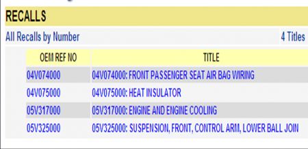
Okay, the last thing I got for you is possible recalls to check on. Since you are a mechanic I am sure you know, but I am going to tell you anyway. Just call the dealer service department and provide the VIN number and see if any of these apply to the car you are working on.
Hope this all helps..........
Mar 25, 2009 at 10:04 PM