Hello -
Thanks for the info..........the problem with P0170 is as you see, there are about 13 different things that would set the code........
I will attach the troubleshooting for you but as you see, you need the equipment to test it. So you will have to either have the tests run or take a chance and change a couple of things to see if that works and then if not......pay to run the tests.........
Me, I would change the PCV valve and right front O2 sensor. But again....please remember if you don't have the equipment to verify what it is this is still a shot in the dark....here is the tests for P0170.
Diagnosis & Repair Procedure
1. Ensure FREEZE FRAME DATA has been recorded. Check for related service bulletins. Repair as necessary and go to next step.
2. Turn ignition off and on. Check for DTCs. See RETRIEVING DIAGNOSTIC TROUBLE CODES under SELF-DIAGNOSTIC SYSTEM. If DTC P0300, P0301, P0302, P0303, P0304, P0305 or P0306 is present, go to step 8 . If any other DTCs are present, repair those DTC(s) first. If no DTC is present but a driveability problem is present, go to step 8 . If no DTC is present and no driveability problem is present, go to next step.
3. Check for DTC P0170 in FREEZE FRAME DATA. If DTC is present, go to next step. If DTC is not present, repair any other DTC(s) present in FREEZE FRAME DATA.
4. Using scan tool, access PID data for MAF V, ECT V, TP V and VS. Turn ignition on. Start engine. Compare readings with specifications when ignition is on and engine is running. If all PID data is within specification, go to next step. If any PID data is not within specification, go to appropriate component or system test. See SYSTEM & COMPONENT TESTING - MIATA, MILLENIA, MPV, PROTEGE & 626 article. Go to step 24 .
5. Using FREEZE FRAME DATA, operate vehicle under same conditions as when DTC was set. Record PID data for MAF V, ECT V, TP V and VS. If all PID data is within specification, go to next step. If any data is not within specification, go to appropriate component or system test. See SYSTEM & COMPONENT TESTING - MIATA, MILLENIA, MPV, PROTEGE & 626 article. Go to step 24 .
6. Check for LONGFT1 in FREEZE FRAME DATA. If LONGFT1 is present, go to next step. If LONGFT1 is not present, go to step 19 .
7. Using scan tool, access PID data for FHO2SR. Depress accelerator pedal to Wide Open Throttle (WOT) and release to race engine. Scan tool should display right front HO2S voltage greater than .45 volt during rich condition and less than .45 volt during lean condition. If voltage is as specified, check for vacuum leaks between air cleaner and throttle body, throttle body and plenum chamber, and plenum chamber and intake manifold. If components are okay, check for loose or damaged vacuum hoses. Repair as necessary and go to step 24 . If voltage is not as specified, check for exhaust system leak upstream of right front HO2S. If exhaust system is okay, replace right front HO2S and go to step 24 .
8. Using scan tool, access MAF V PID data. Depress accelerator pedal to Wide Open Throttle (WOT) and release to race engine. If MAF V PID respond quickly to change in engine RPM, go to next step. If MAF V PID does not respond quickly to change in engine RPM, replace MAF sensor and go to step 24 .
9. Check for lose or damaged vacuum hoses. Repair as necessary and go to step 24 . If vacuum hoses are okay, go to next step.
10. Turn ignition off. Check fuel line pressure with engine running. See BASIC DIAGNOSTIC PROCEDURES article. If engine will not start, check fuel line pressure with ignition key in ON position. If fuel line pressure is 45-51 psi (3.1-3.6 kg/cm2 ), go to step 14 . If fuel line pressure is more than 45-51 psi (3.1-3.6 kg/cm2 ), go to next step. If fuel line pressure is less than 45-51 psi (3.1-3.6 kg/cm2 ), go to step 12 .
11. Ensure engine is running. Check for vacuum at fuel pressure regulator. If vacuum is present, check fuel pump maximum pressure. See BASIC DIAGNOSTIC PROCEDURES article. If fuel pump maximum pressure is okay, check fuel return line for plugging. Repair or replace as necessary. If fuel return line is okay, replace pressure regulator and go to step 24 . If vacuum is not present, ensure fuel pressure regulator vacuum hose is okay. Repair or replace as necessary and go to step 24 . If vacuum hose is okay, replace PRC solenoid valve and go to step 24 .
12. Check fuel pump maximum pressure. See BASIC DIAGNOSTIC PROCEDURES article. If fuel pump maximum pressure is 86-110 psi (6-8 kg/cm2 ), go to next step. If fuel pump maximum pressure is not 86-110 psi (6-8 kg/cm2 ), check for open fuel pump circuits. Repair as necessary and go to step 24 . If fuel pump circuits are okay, replace fuel pump and go to step 24 .
13. Check for leaks in fuel system downstream of fuel pump. If any leaks are found, repair as necessary and go to step 24 . If no leaks are found, check for plugging at fuel filter and fuel inlet filter (sock). If plugging is present, check fuel tank for debris. If fuel tank is okay, replace fuel filter and go to step 24 . If fuel tank has debris, clean tank, replace fuel inlet filter (sock) and fuel filter. If fuel tank, fuel filter and fuel inlet filter (sock) are okay, replace fuel pressure regulator and go to step 24 .
14. Access and switch fuel injector in suspect cylinder with injector in the opposite bank. Recheck while operating vehicle under conditions similar to when DTC was set. If DTC changes to cylinder where suspect injector is installed, replace injector and go to step 24 . If DTC does not change, go to next step.
15. Check primary and secondary ignition system. If both primary and secondary ignition systems are okay, go to step 18 . If secondary ignition system is not operating properly, repair or replace as necessary. If primary ignition system is not operating properly, go to next step.
NOTE: Ignition coil is integrated into distributor and is not serviced separately. To replace ignition coil, replace complete distributor assembly.
16. Disconnect ignition coil 3-pin connector at distributor. Turn ignition on. Measure voltage at ignition coil harness connector terminal "D" (Black/White wire). If battery voltage is present, go to next step. If battery voltage is not present, repair open in Black/White wire between ignition coil and ignition switch and go to step 24 . See WIRING DIAGRAMS article.
17. Check ignition coil resistance. See BASIC DIAGNOSTIC PROCEDURES article. If coil is okay, go to step 24 . If coil is faulty, replace distributor and go to step 24 .
18. Check engine compression. Engine compression should be a minimum of 130 psi (9 kg/cm2 ) at 300 RPM with a maximum variation of 28 psi. If compression is as specified, go to step 24 . If compression is not as specified, repair as necessary and go to step 24 .
19. Using scan tool, access PID data for FHO2SR. Depress accelerator pedal to Wide Open Throttle (WOT) and release to race engine. Scan tool should display right front HO2S voltage greater than .45 volt during rich condition and less than .45 volt during lean condition. If voltage is as specified, go to next step. If voltage is not as specified, replace right front HO2S and go to step 24 .
20. Turn ignition off. Check fuel line pressure with engine running. See BASIC DIAGNOSTIC PROCEDURES article. If engine will not start, check fuel line pressure with ignition key in ON position. If fuel line pressure is 45-51 psi (3.1-3.6 kg/cm2 ), go to step 22 . If fuel line pressure is not 45-51 psi (3.1-3.6 kg/cm2 ), go to next step.
21. Ensure engine is running. Check for vacuum at fuel pressure regulator. If vacuum is present, check fuel pump maximum pressure. See BASIC DIAGNOSTIC PROCEDURES article. If fuel pump maximum pressure is okay, check fuel return line for plugging. Repair or replace as necessary. If fuel return line is okay, replace pressure regulator and go to step 24 . If vacuum is not present, ensure fuel pressure regulator vacuum hose is okay. Repair or replace as necessary and go to step 24 . If vacuum hose is okay, replace PRC solenoid valve and go to step 24 .
22. Turn ignition off. Disconnect hoses from purge solenoid valve. Apply low-pressure air through purge solenoid valve. If air flows through, replace purge solenoid valve and go to step 24 . If air does not flow through, go to next step.
23. Check PCV system. If PCV system is okay, go to next step. If a problem is found, repair as necessary and go to next step.
24. Reconnect all connectors. Clear DTCs. See CLEARING DIAGNOSTIC TROUBLE CODES under SELF-DIAGNOSTIC SYSTEM. Using scan tool, perform PCM adaptive memory drive mode, EGR monitor repair verification drive mode and HO2S/TWC monitor repair verification drive mode. See DRIVE MODES . Check for DTCs. See RETRIEVING DIAGNOSTIC TROUBLE CODES under SELF-DIAGNOSTIC SYSTEM. If DTC P0170 is present, replace PCM and go to next step. On vehicles equipped with immobilizer system, reprogram ignition key identification numbers. See COMPUTER RELEARN PROCEDURES article in GENERAL INFORMATION. If DTC P0170 is not present, go to next step.
25. Cycle ignition from off to on. Check for DTCs. See RETRIEVING DIAGNOSTIC TROUBLE CODES under SELF-DIAGNOSTIC SYSTEM. If any other DTC is present, go to appropriate test.
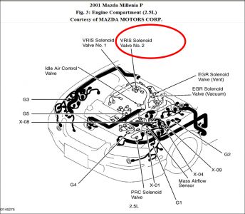
As for code P1522 the Variable Resonance Induction System (VRIS) Solenoid Valve No. 2 Circuit Malfunction - I again will attach the troubleshooting for it. Figure 8 will be at the end for ease. For me I would take a chance and change the solenoid - that pic and location is at the end.
Diagnosis & Repair Procedure
1. Check for related service bulletins. Repair as necessary and go to next step.
2. Turn ignition off and on. Check for DTCs. See RETRIEVING DIAGNOSTIC TROUBLE CODES under SELF-DIAGNOSTIC SYSTEM. If DTC P1522 is present, go to next step. If DTC P1522 is not present, problem is intermittent. See TROUBLE SHOOTING - NO CODES article.
3. Disconnect vacuum hose between VRIS solenoid valve No. 2 and intake manifold. Using vacuum pump, apply vacuum to VRIS solenoid valve No. 2. If vacuum holds for 5 seconds, go to step 5 . If vacuum does not hold for 5 seconds, go to next step.
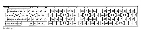
4. Turn ignition off. Disconnect VRIS solenoid valve No. 2 connector. If vacuum holds, repair short to ground in Brown/Yellow wire between VRIS solenoid valve No. 2 and PCM connector terminal No. 1AE. See Fig. 8 . See WIRING DIAGRAMS article. Go to step 10 . If vacuum does not hold, replace VRIS solenoid valve No. 2 and go to step 10 .
5. Disconnect VRIS solenoid valve No. 2 connector. Check for damaged or corroded VRIS solenoid valve No. 2 connector terminals. Repair as necessary, and go to step 10 . If connector terminals are okay, go to next step.
6. Measure resistance between VRIS solenoid valve No. 2 connector terminals. If resistance is 38-42 ohms, go to next step. If resistance is not 38-42 ohms, replace VRIS solenoid valve No. 2 and go to step 10 .
7. Turn ignition on. Measure voltage between VRIS solenoid valve No. 2 harness connector terminal "A" (Red/Black wire) and ground. If battery voltage is present, go to next step. If battery voltage is not present, repair open in Red/Black wire between VRIS solenoid valve No. 2 and main relay. See WIRING DIAGRAMS article. Go to step 10 .
8. Turn ignition off. Disconnect appropriate PCM connector. PCM is mounted in front of center console, under radio. Check for damaged or corroded PCM connector terminals. Repair as necessary, and go to step 10 . If connector terminals are okay, go to next step.
9. Reconnect VRIS solenoid valve No. 2 connector. Turn ignition on. Measure voltage between PCM harness connector terminal No. 1AE (Brown/Yellow wire) and ground. See Fig. 8 . If battery voltage is present, go to next step. If battery voltage is not present, repair open in Brown/Yellow wire between PCM and VRIS solenoid valve No. 2. See WIRING DIAGRAMS article. Go to next step.
10. Reconnect all connectors. Turn ignition off and on. Check for DTCs. See RETRIEVING DIAGNOSTIC TROUBLE CODES under SELF-DIAGNOSTIC SYSTEM. If DTC P1522 is present, replace PCM and go to next step. On vehicles equipped with immobilizer system, reprogram ignition key identification numbers. See COMPUTER RELEARN PROCEDURES article in GENERAL INFORMATION. If DTC P1522 is not present, go to next step.
11. Cycle ignition from off to on. Check for DTCs. See RETRIEVING DIAGNOSTIC TROUBLE CODES under SELF-DIAGNOSTIC SYSTEM. If any other DTC is present, go to appropriate test.
Oct 3, 2009 at 10:15 PM