1992 Mazda 626 Stuck on hot and can't change direction of a

Tiny
MANDRAS
  • MEMBER
  • 1992 MAZDA 626
  • 6 CYL
  • 2WD
  • MANUAL
  • 150,000 MILES
Would love some suggestions of what to look at - all the AirCon switching on the Mazda 626 do not change the direction of the airflow to the windshield. And a potential seperate but significant problem is that the air is always hot - when moving to the cool on the thermo it is still stuck on very hot. I have the service manual - could you quickly outline for me what I should check? Also - how can I access the air conditioning system do I need to disassemble the entire inside dash of the car down to the firewall? What is the best way to access it?
Saturday, January 3rd, 2009 AT 5:22 AM

4 Replies

Tiny
DAVE H
  • MECHANIC
  • 13,383 POSTS
Hello. And thanks for the donation

Sounds like your control doors are not functioning correctly. You will need to remove the dashboard i'm afraid to check these. Let me know if you need any of the diagrams listed below?
OPERATION
BLOWER MOTOR CIRCUIT
Blower motor relay supplies power to blower motor. Blower resistor determines blower speed. With blower switch in highest position, blower motor is grounded through blower switch. With blower switch in all other positions, blower motor is grounded through blower resistor and blower switch.
COMPRESSOR CLUTCH CIRCUIT
Circuit through compressor clutch is completed when A/C relay is energized and pressure switch is closed. A/C relay is energized when Engine Control Unit (ECU) unit grounds the solenoid circuit of the A/C relay.
AIR CONTROL DOORS
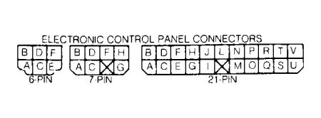
Electronic Control Panel
Each air control door is controlled by an actuator motor.
Manual Control Panel
Air control doors are controlled by slide lever attached to cable. Top left lever controls the temperature blend door, top right lever controls the fresh/recirculated air door, and bottom left lever controls the airflow mode door.

DOOR ACTUATORS
Airflow Mode
Remove instrument panel. See INSTRUMENT PANEL under REMOVAL & INSTALLATION. Disconnect actuator connector. See Fig. 4. Apply battery voltage across actuator connector terminals "c" and "b".
Actuator should move door. Reverse battery leads. Actuator should move door in opposite direction. Replace actuator if door does not move as specified.
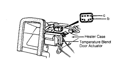
Fig. 4: Airflow Mode Door Actuator Connector Terminal ID
Courtesy of MAZDA MOTORS CORP.
Fresh/Recirculated Air
Remove undercover and glove box. Disconnect actuator connector. See Fig. 5. Apply battery voltage across actuator connector terminals "e" and "f". Actuator should move door. Reverse battery leads. Actuator should move door in opposite direction. Replace actuator if door does not move as specified.
Fig. 5: Fresh/Recirculated Air Door Actuator Connector Terminal ID
Courtesy of MAZDA MOTORS CORP.
Temperature Blend
Remove instrument panel. See INSTRUMENT PANEL under REMOVAL & INSTALLATION. Disconnect actuator connector. See Fig. 6. Apply battery voltage across actuator connector terminals "c" and "b".
Actuator should move door. Reverse battery leads. Actuator should move door in opposite direction. Replace actuator if door does not move as specified.
Was this
answer
helpful?
Yes
No
Saturday, January 3rd, 2009 AT 7:57 AM
Tiny
MANDRAS
  • MEMBER
  • 3 POSTS
- yes would love to see the diagrams on the actuator - just to confirm the wiring harness to test is actually behind the dashboard ( the actual gauges? ) - I was thinking maybe I can test from the main harness in the back of the ac computer which is easy to access - you wouldn't have the pinout for the connection on the back would you? Thanks a lot!
Was this
answer
helpful?
Yes
No
Saturday, January 3rd, 2009 AT 11:27 AM
Tiny
MANDRAS
  • MEMBER
  • 3 POSTS
. Its actually a Ford Telstar 1992 - which is identical to the Mazda 626 - but the dash is slightly different. I am worried the pinout might be difference for the AC control module- not sure if you have any advice on this as I think the Telstar is not sold in the states.
Was this
answer
helpful?
Yes
No
Saturday, January 3rd, 2009 AT 12:18 PM
Tiny
DAVE H
  • MECHANIC
  • 13,383 POSTS
I don't have a diagram for the telstar ... you will have to look and see if the are the same .. ?? chances are if the connectors are the same the wiring is the same ? if you do voltage and ground test's and the pins are the same then I would guess the rest are the same ?

Airflow Mode Control Circuit
Remove control panel. See CONTROL PANEL under REMOVAL & INSTALLATION. On back of control panel, connect battery positive lead to terminal "D" of 7-pin connector and negative lead to terminal "L" of 21-pin connector. See Fig. 7 . Leave battery connected to these terminals during testing procedures.
Connect jumper wire between terminals "I" and "L" of 21-pin connector. Connect a resistance of at least 1000 ohms between terminals "D" and "L" of 21-pin connector. Check voltage between terminals "D" and "L" of 21-pin connector. If about 12 volts is present, go to next step. If about 12 volts is NOT present, replace control panel.
Disconnect resistance and jumper wire connected in step 2). Connect a jumper wire between terminals "C" and "L" of 21-pin connector. Connect a resistance of at least 1000 ohms between terminals "A" and "L" of 21-pin connector. Check voltage between terminals "A" and "L" of 21-pin connector. If about 12 volts is present, go to next step. If about 12 volts is NOT present, replace control panel.
Disconnect resistance and jumper wire connected in step 3). Connect a resistance of at least 1000 ohms between terminal "D" of 7-pin connector and terminal "D" of 21-pin connector. Check voltage between terminals "D" and "L" of 21-pin connector. If less than one volt is present, go to next step. If more than one volt is present, replace control panel.
Disconnect resistance connected in step 4). Connect a resistance of at least 1000 ohms between terminal "D" of 7-pin connector and terminal "A" of 21-pin connector. Check voltage between terminals "A" and "L" of 21-pin connector. If less than one volt is present, go to next step. If more than one volt is present, replace control panel.
Disconnect resistance connected in step 5). As specified in AIRFLOW MODE CONTINUITY TEST table, select airflow mode and check continuity between indicated terminals of 21-pin connector. If there is no continuity between indicated terminals, replace control panel. If continuity is as indicated, airflow mode control circuit is okay.
AIRFLOW MODE CONTINUITY TEST
Mode Button...........Continuity Between Terminals
VENT..........................................J & L
BI-LEVEL.....................................G & L
HEAT.........................................H & L
HEAT-DEFROST...........................E & L
DEFROST....................................F & L


https://www.2carpros.com/forum/automotive_pictures/266999_control_1.jpg


https://www.2carpros.com/forum/automotive_pictures/266999_temp_1.jpg

Was this
answer
helpful?
Yes
No
Sunday, January 4th, 2009 AT 7:25 AM

Please login or register to post a reply.

Sponsored links