Hi,
It should be the same. If I recall, changes were made to the supercharger. As far as replacement, here are directions for the lower manifold. I'm adding them because they include torque specs.
________________________________
2003 Pontiac Grand Prix V6-3.8L SC VIN 1
Intake Manifold Replacement - Lower
Vehicle Engine, Cooling and Exhaust Engine Intake Manifold Service and Repair Removal and Replacement Intake Manifold Replacement - Lower
INTAKE MANIFOLD REPLACEMENT - LOWER
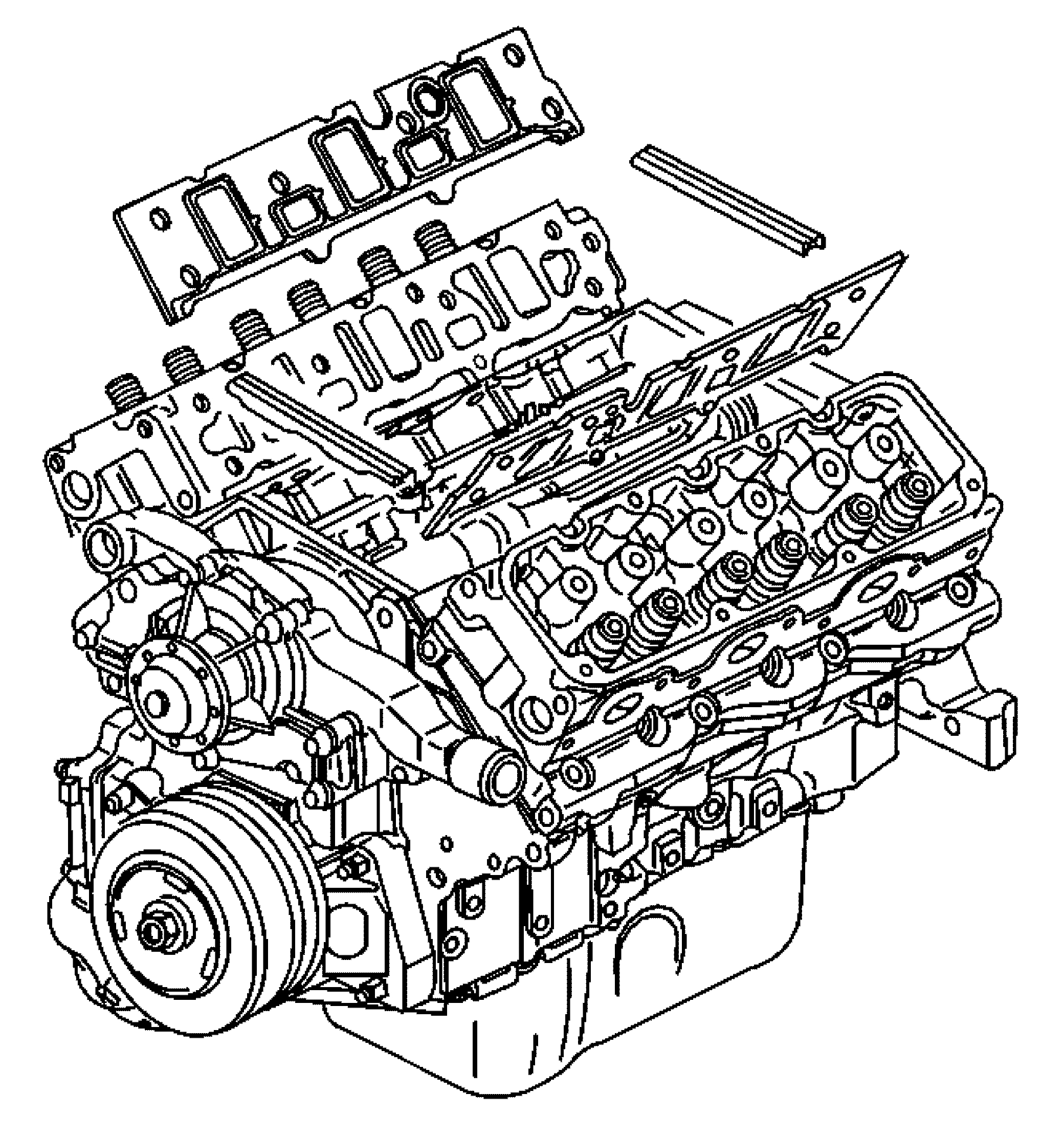
Lower Intake Manifold Replacement (L67)
Removal Procedure
1. Drain the cooling system.
2. Remove the supercharger.
pic 1
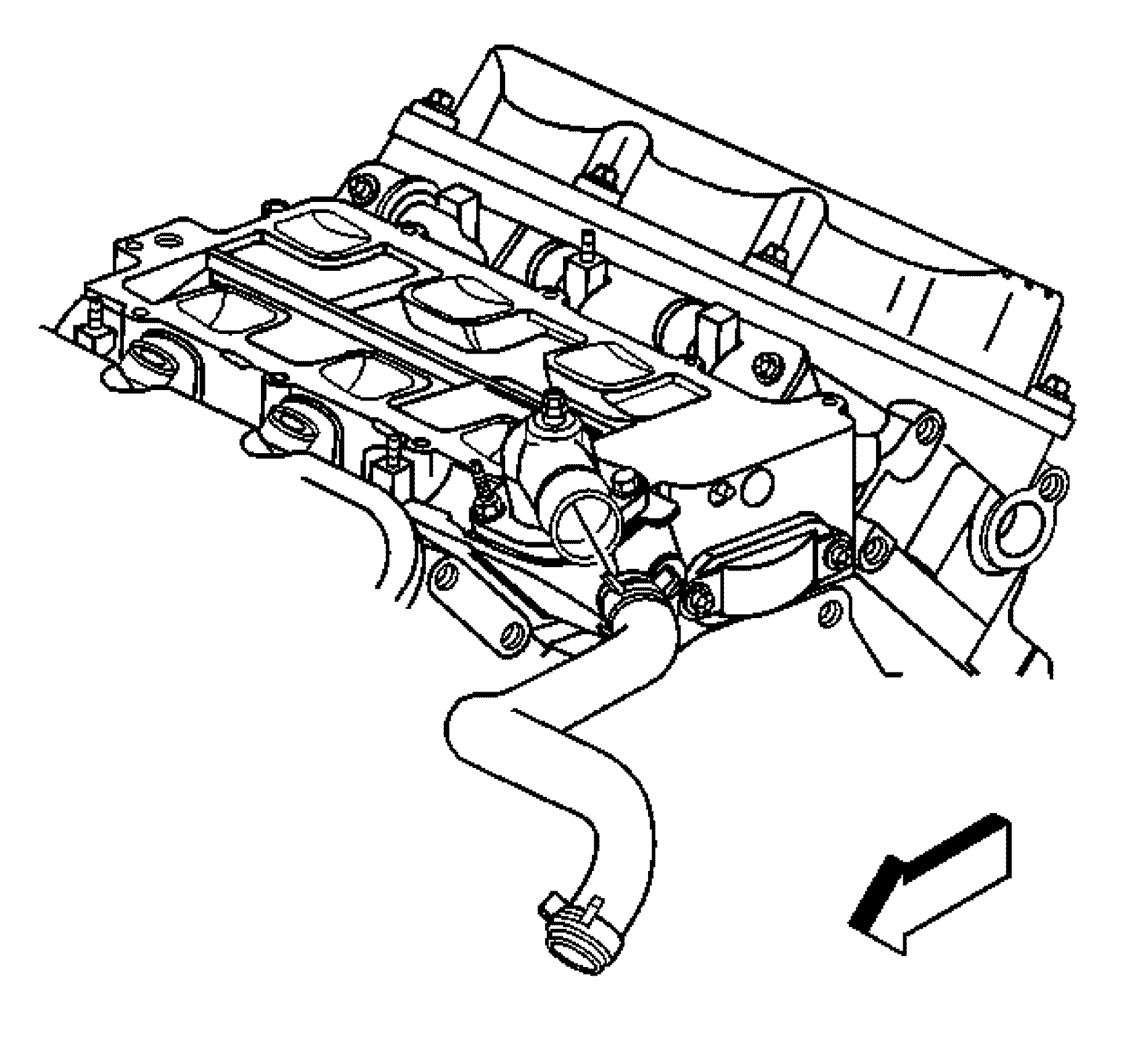
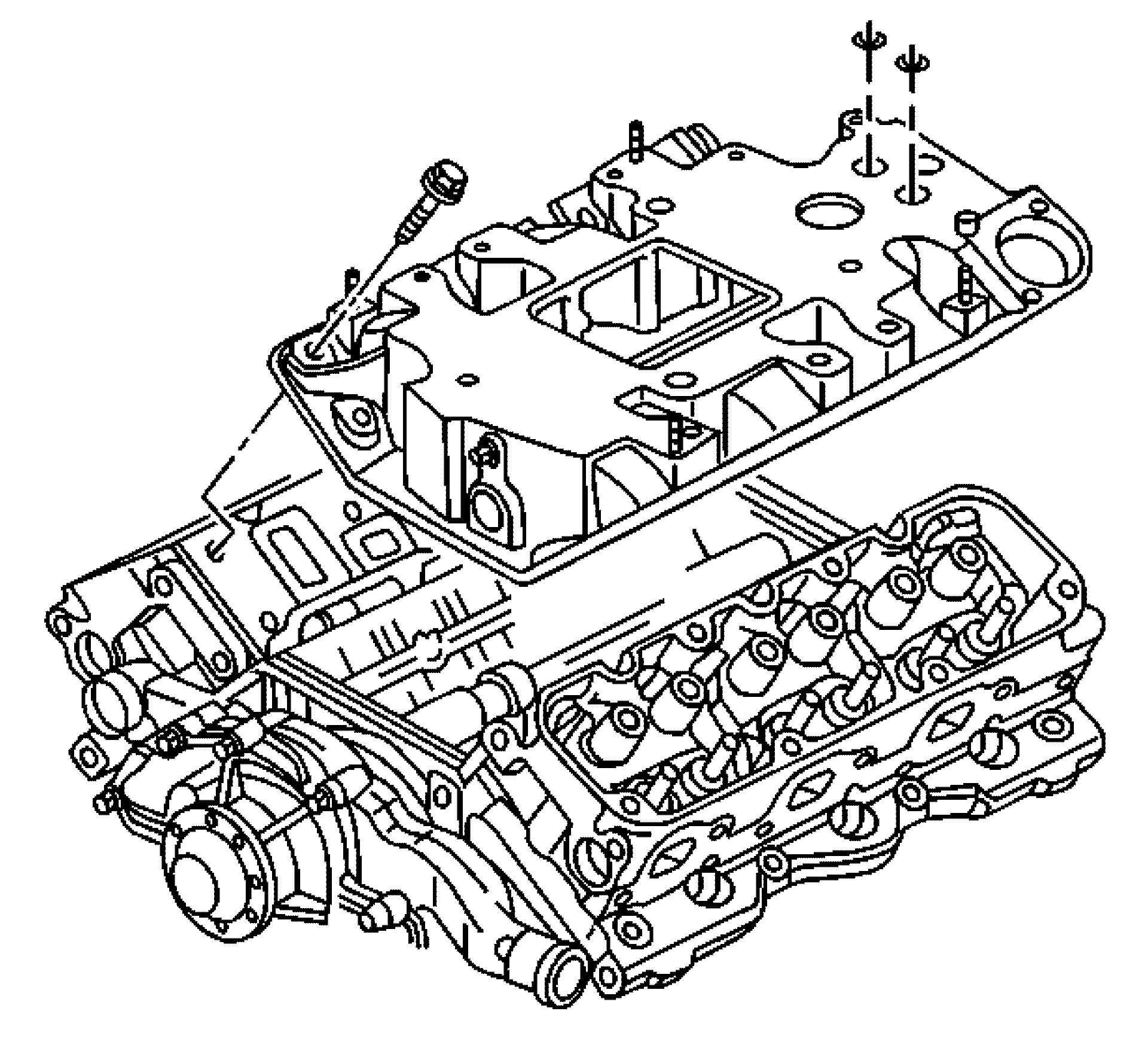
3. Remove the radiator inlet hose from the water outlet housing.
pic 2
4. Remove the exhaust gas recirculation (EGR) outlet pipe bolt from the lower intake manifold.
5. Remove the EGR outlet pipe from the lower intake manifold.
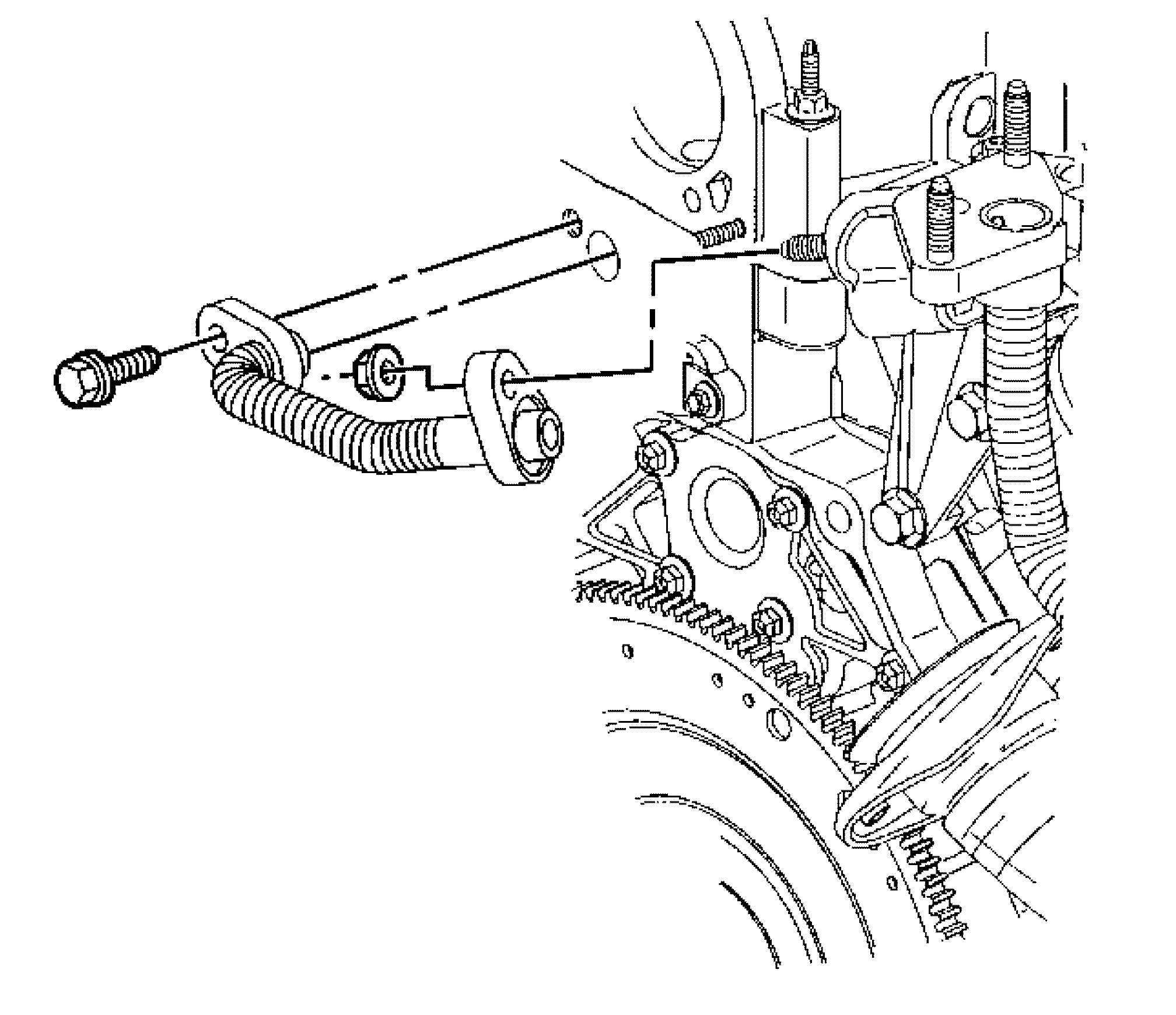
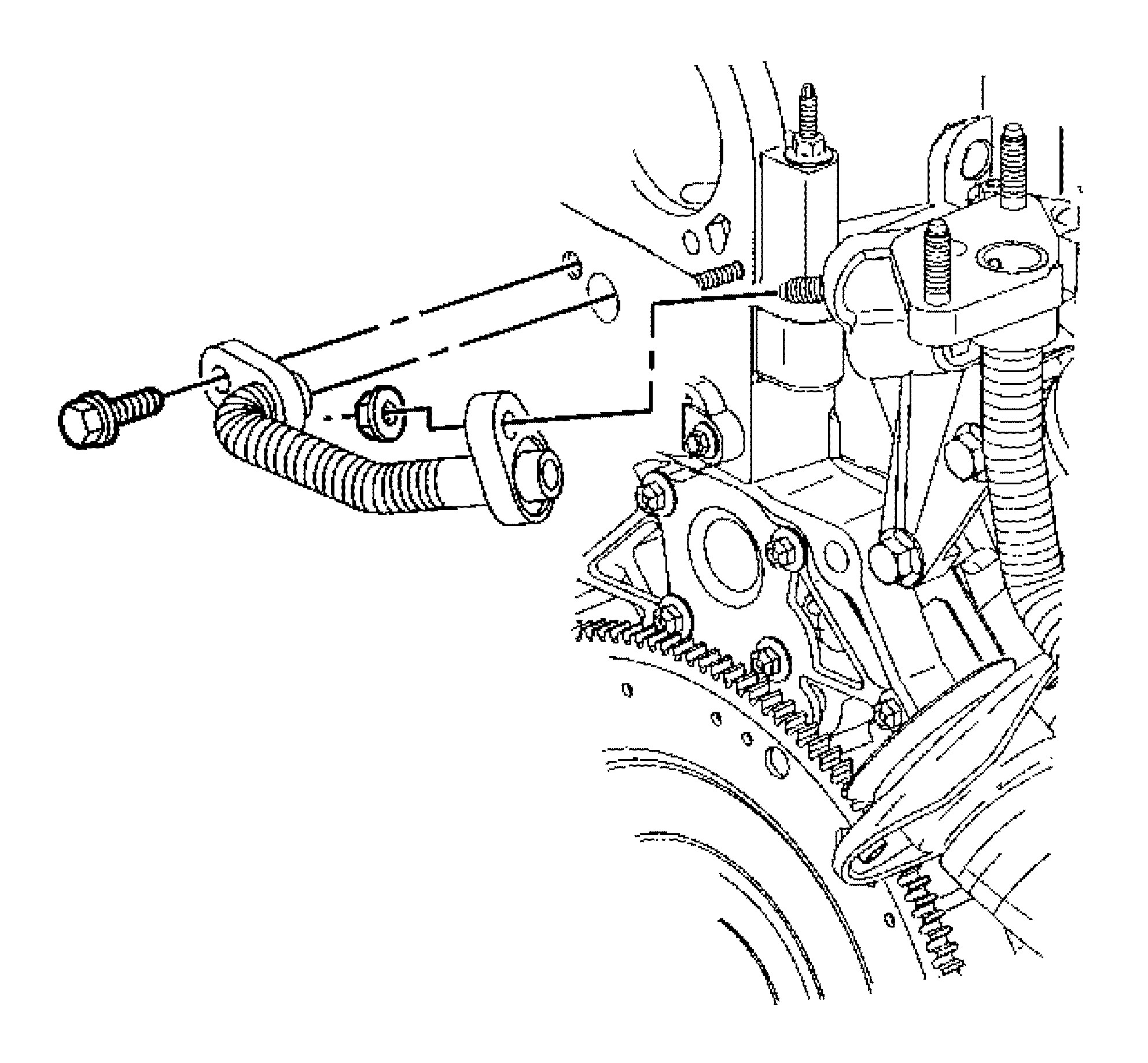
6. Disconnect the engine coolant temperature (ECT) sensor electrical connector.
pic 3
7. Remove the lower intake manifold bolts.
8. Remove the lower intake manifold. The coolant bypass tube will release from the intake manifold as the manifold is removed.
9. Remove the lower intake manifold seals.
10. Remove the lower intake manifold gaskets.
11. If replacing the lower intake manifold, remove the water outlet housing and the thermostat.
12. If replacing the lower intake manifold, remove the ECT sensor.
13. Inspect the flatness of the inlet flanges.
14. Clean the lower intake manifold mating surfaces.
15. Clean the intake manifold bolts and the bolt holes of the adhesive compound.
Installation Procedure
Notice: Use the correct fastener in the correct location. Replacement fasteners must be the correct part number for that application. Fasteners requiring replacement or fasteners requiring the use of thread locking compound or sealant are identified in the service procedure. Do not use paints, lubricants, or corrosion inhibitors on fasteners or fastener joint surfaces unless specified. These coatings affect fastener torque and joint clamping force and may damage the fastener. Use the correct tightening sequence and specifications when installing fasteners in order to avoid damage to parts and systems.
1. If removed, install the ECT sensor.
Tighten
Tighten the ECT sensor to 25 Nm (18 lb ft).
pic 3
2. If removed, install the thermostat, the gasket, and the water outlet housing.
3. Install the water outlet housing bolt and the stud.
Tighten
Tighten the bolt and the stud to 27 Nm (20 lb ft).
pic 4
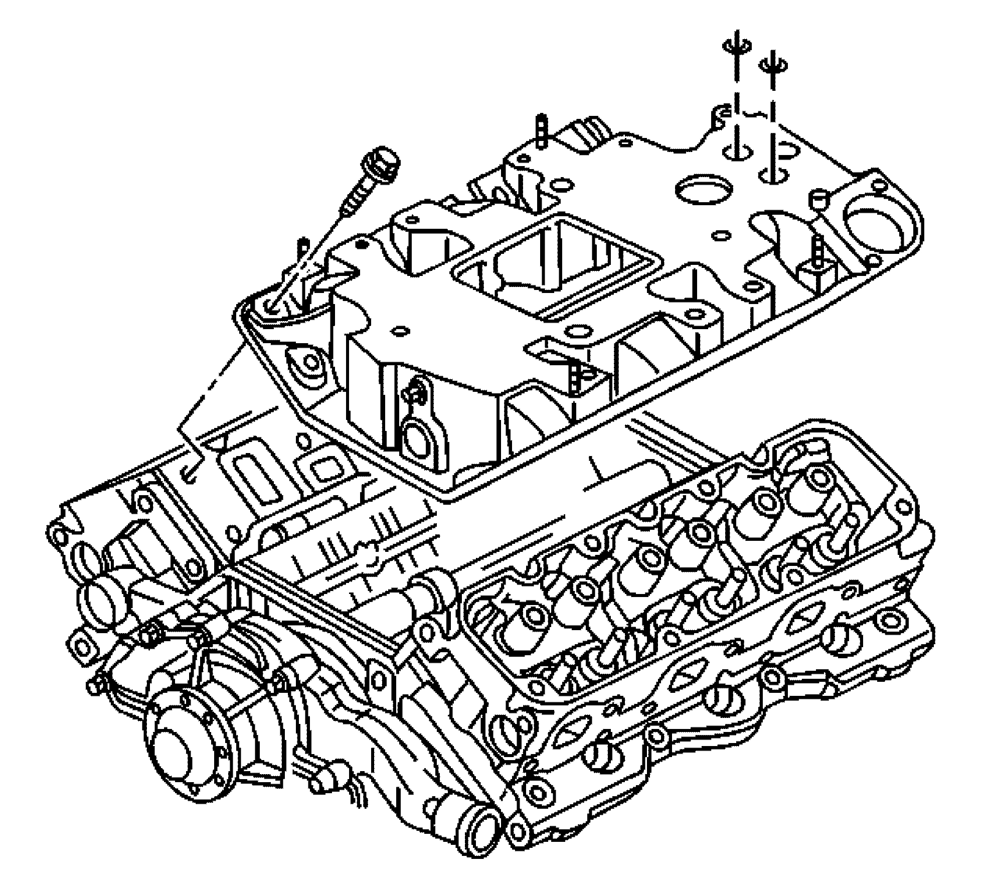
4. Install the intake manifold gaskets.
5. Apply sealer, GM P/N 12346286 (Canadian P/N 10953472) or equivalent, to the ends of the intake seals.
6. Install the lower intake manifold seals.
pic 5
7. Align the coolant bypass tube with the opening in the manifold. Install the lower intake manifold.
8. Install the lower intake manifold bolts.
Tighten
Tighten the lower intake manifold bolts from the center to the outside in sequence to 15 Nm (11 lb ft).
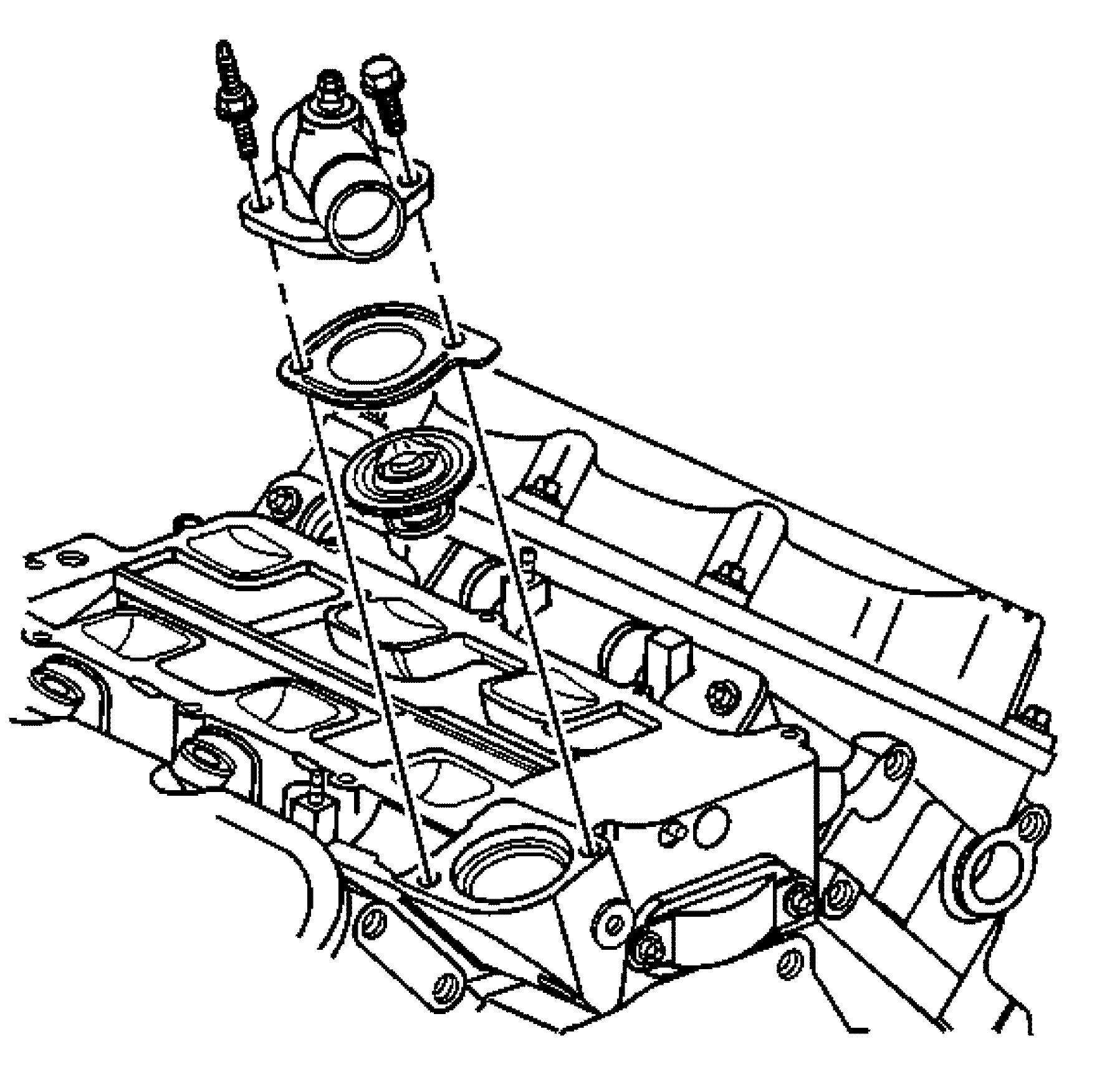
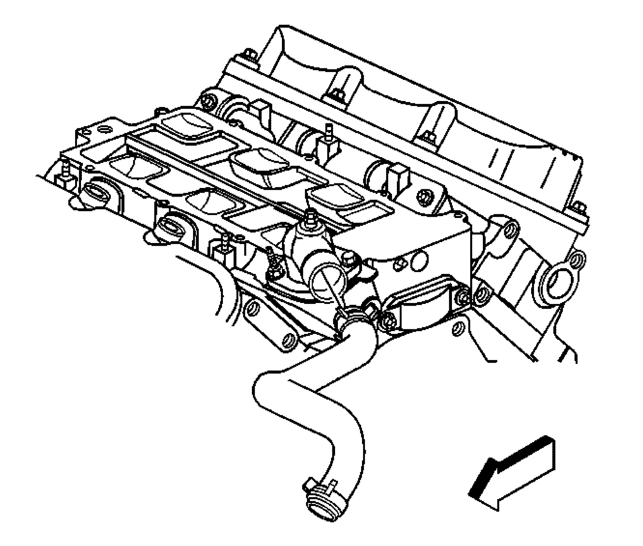
9. Connect the ECT sensor electrical connector.
pic 6
10. Install the EGR outlet pipe to the lower intake manifold.
11. Install the EGR outlet pipe bolt.
Tighten
Tighten the bolt to 29 Nm (21 lb ft).
pic 7
12. Install the radiator inlet hose to the water outlet housing.
13. Install the supercharger.
14. Fill the cooling system.
15. Inspect for fluid or vacuum leaks.
___________________________
I hope this helps. Let me know if you have other questions.
Take care and God Bless,
Joe
Images (Click to enlarge)
Mar 9, 2021 at 7:17 PM