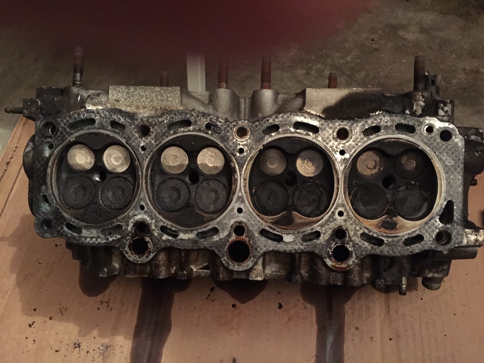
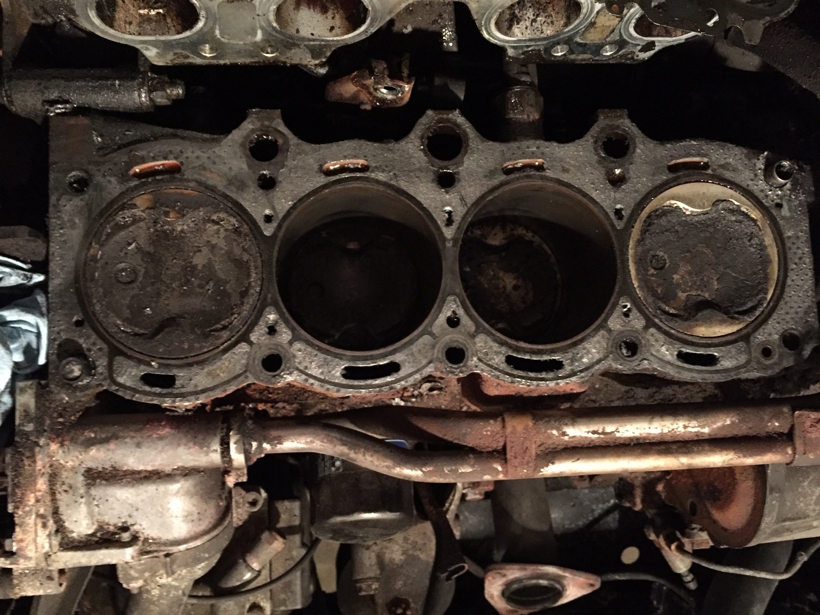
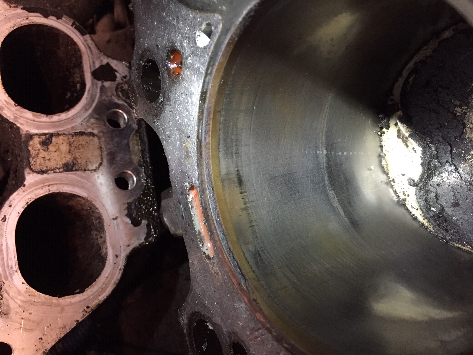
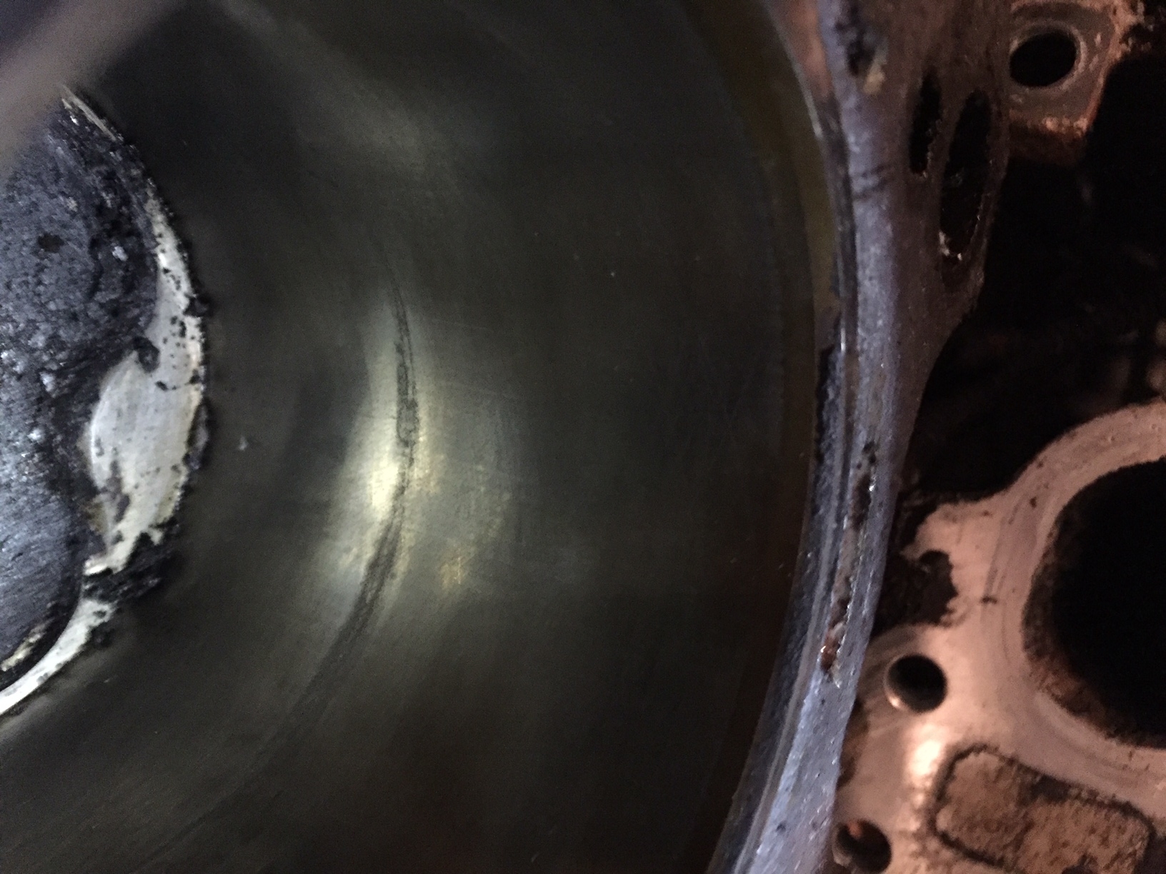
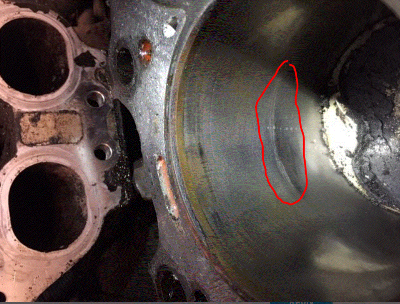
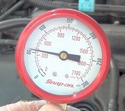
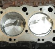
Ugh, that isn't good news. I suspect you are correct. It's interesting that two of them did the same thing nearly at the same place.
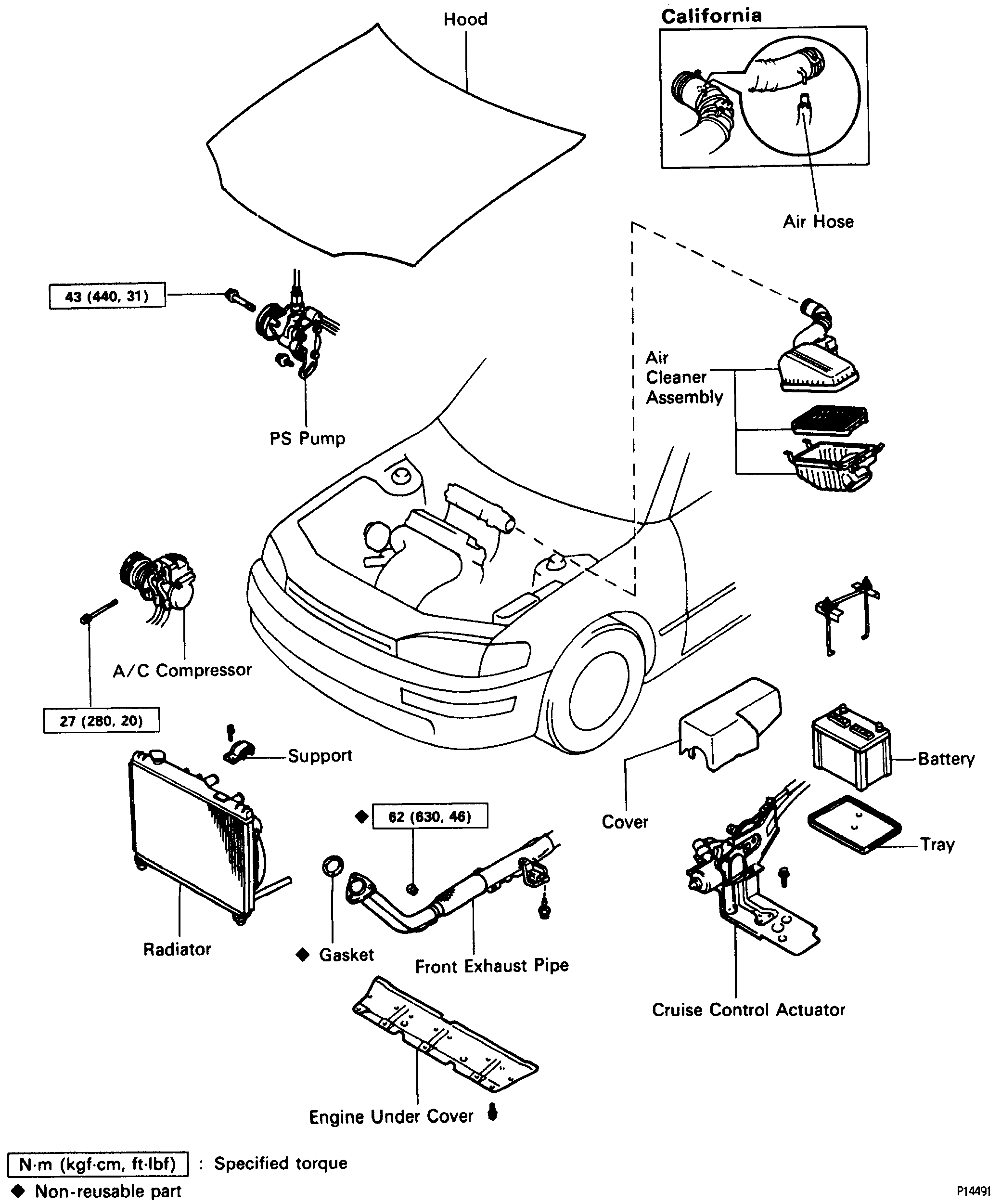
I don't know if you plan to replace the engine, but here are the directions if you want them. Be prepared, they are extensive.
______________________
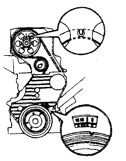
1994 Toyota Camry Sedan 4-Door L4-132 2164cc 2.2L DOHC (5S-FE)
Removal and Installation
Vehicle Engine, Cooling and Exhaust Engine Service and Repair Procedures Removal and Installation
REMOVAL AND INSTALLATION
pic 1
pic 2
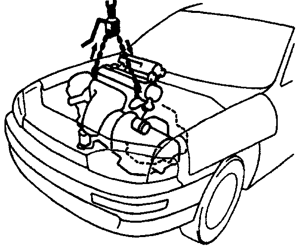
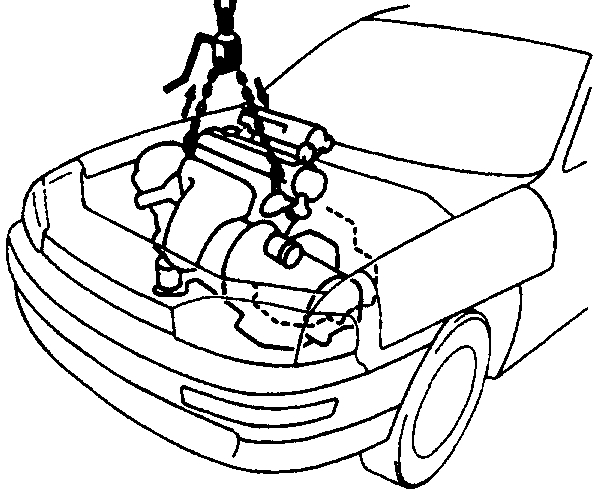
ENGINE REMOVAL
pic 3
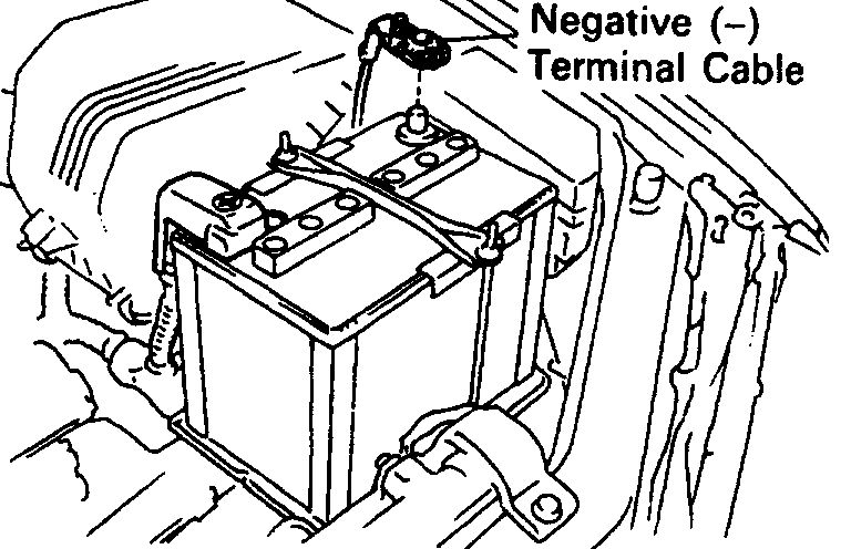
1. DISCONNECT NEGATIVE (-) TERMINAL CABLE FROM BATTERY
CAUTION: Work must be started after 90 seconds from the time the ignition switch is turned to the LOCK position and the negative (-) terminal cable 1s disconnected from the battery.
2. REMOVE BATTERY AND TRAY
3. REMOVE HOOD
4. REMOVE ENGINE UNDER COVER
5. DRAIN ENGINE COOLANT
6. DRAIN ENGINE OIL
7. DISCONNECT ACCELERATOR CABLE FROM THROTTLE BODY
8. A/T: DISCONNECT THROTTLE CABLE FROM THROTTLE BODY
pic 4
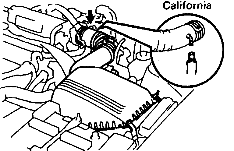
9. REMOVE AIR CLEANER ASSEMBLY, RESONATOR AND AIR CLEANER HOSE
(a) Disconnect the intake air temperature sensor connector.
(b) California only: Disconnect the air hose from the air cleaner hose.
(c) Loosen the air cleaner hose clamp bolt.
(d) Disconnect the 4 air cleaner cap clips.
(e) Disconnect the air cleaner hose from the throttle body. And remove the air cleaner cap together with the resonator and air cleaner hose.
(f) Remove the element.
(g) Remove the 3 bolts and air cleaner case.
Pic 5
10. W/ CRUISE CONTROL SYSTEM: REMOVE CRUISE CONTROL ACTUATOR
(a) Remove the actuator cover.
(b) Disconnect the actuator connector.
(c) Remove the 3 bolts, and disconnect the actuator with the bracket.
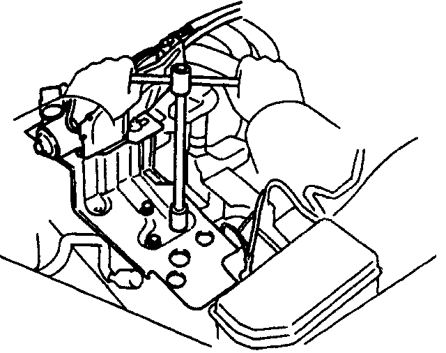
11. REMOVE RADIATOR
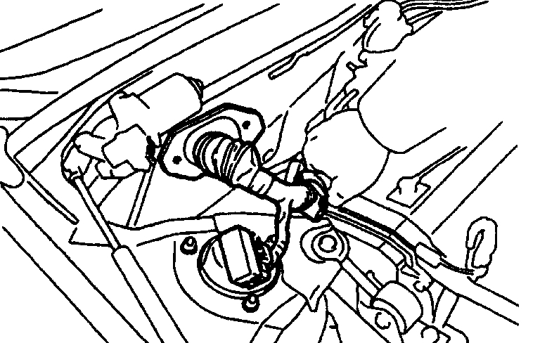
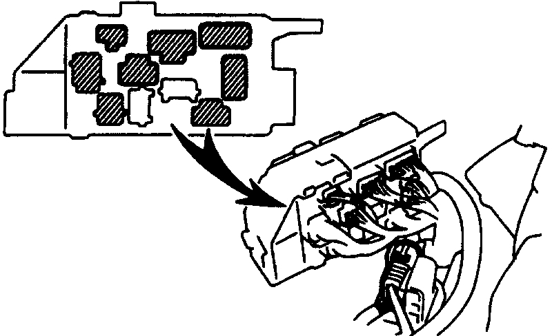
12. DISCONNECT WIRES AND CONNECTORS
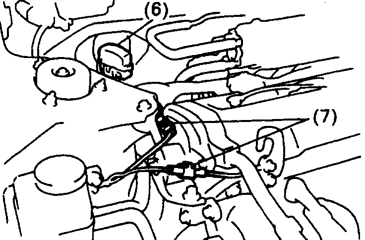
pic 6
(a) Remove the engine relay box. And disconnect the 5 connectors.
(b) Connector from LH fender apron
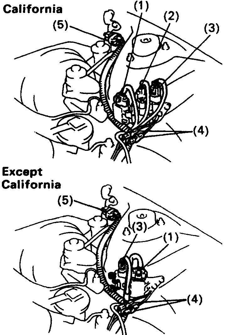
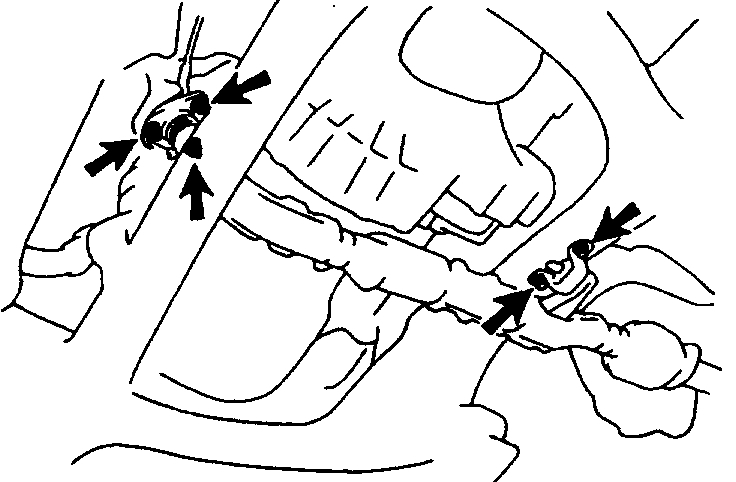
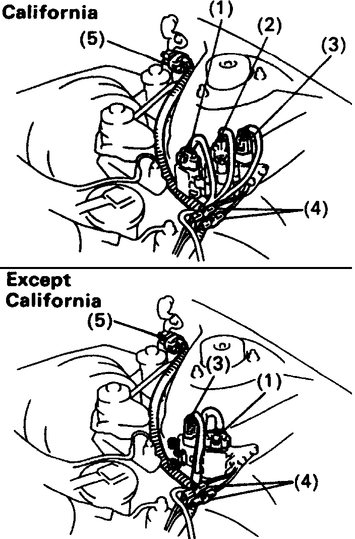
(c) Disconnect the following connectors:
pic 7
(1) Igniter connector
(2) California only: Ignition coil connector
(3) Noise filter connector
(4) 2 ground straps from LH fender apron
(5) Connector from LH fender apron
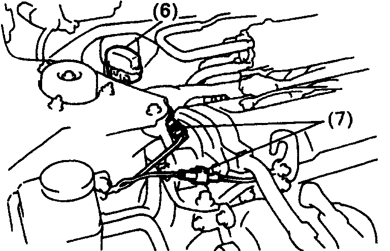
pic 8
(6) Data link connector 1
(7) 2 ground straps from RH fender apron
(d) Disconnect the MAP sensor connector.
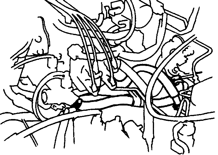
Pic 9
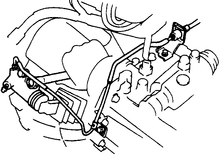
13. DISCONNECT HEATER HOSES
14. DISCONNECT FUEL RETURN HOSE
CAUTION: Catch leaking fuel in a container.
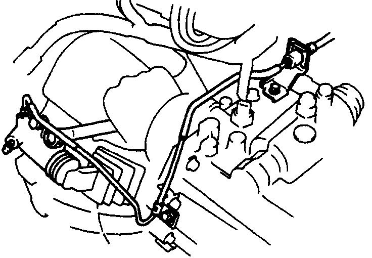
Pic 10
15. DISCONNECT FUEL INLET HOSE
CAUTION: Catch leaking fuel in a container.
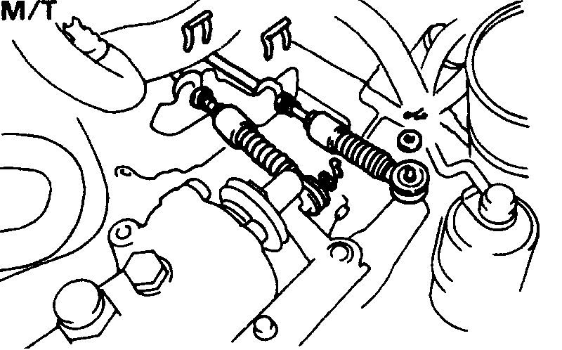
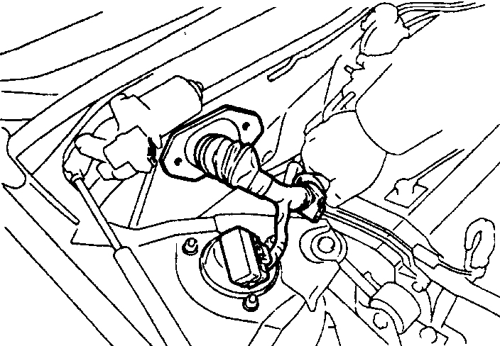
16. M/T: REMOVE STARTER
pic 11
17. M/T: REMOVE CLUTCH RELEASE CYLINDER WITHOUT DISCONNECTING TUBE
- Remove the 4 bolts, release cylinder and tube from the transaxle.
Pic 12
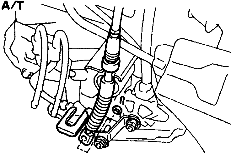
pic 13
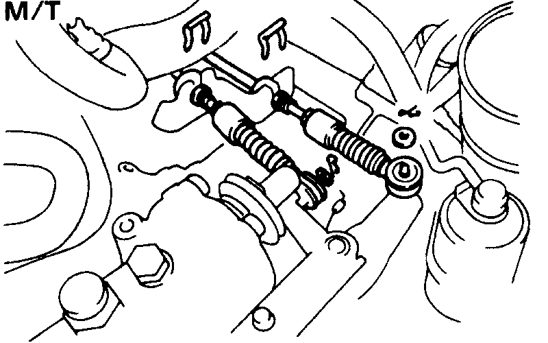
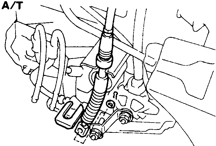
18. DISCONNECT TRANSAXLE CONTROL CABLE(S) FROM TRANSAXLE
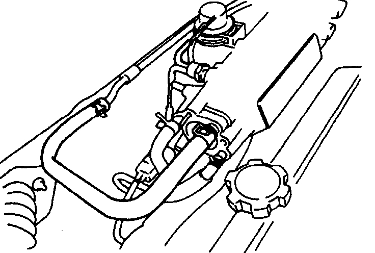
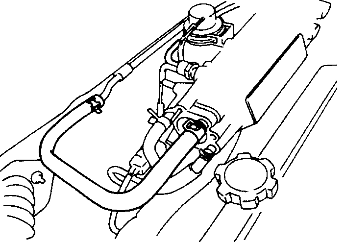
19. DISCONNECT VACUUM HOSES
pic 14
(a) MAP sensor hose from air intake chamber
(b) Brake booster vacuum hose from air intake chamber
(c) Charcoal canister vacuum hose
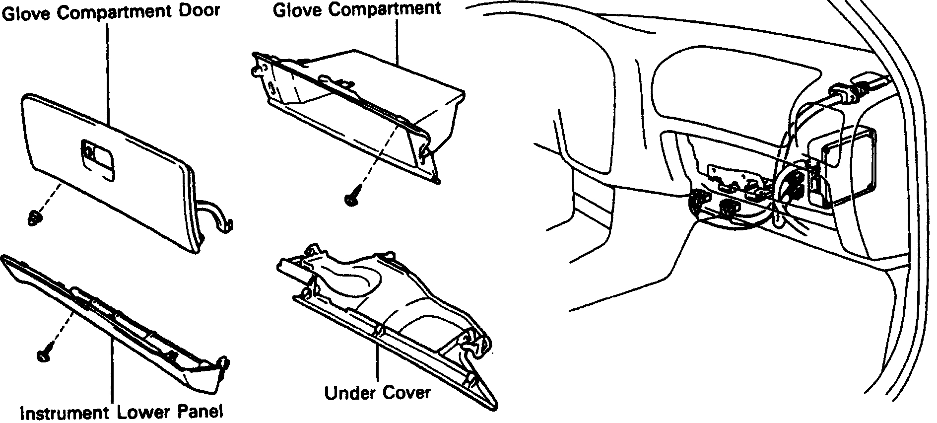
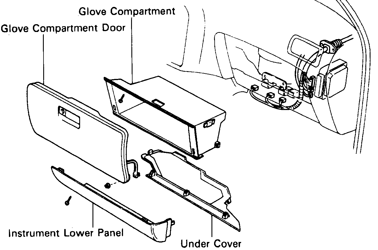
20. DISCONNECT ENGINE WIRE FROM CABIN
pic 15
(a) Remove the under cover.
(b) Remove the lower instrument panel.
(c) Remove the glove compartment door.
(d) Remove the glove compartment.
(e) Disconnect the following connectors:
(1) 2 ECM connectors
(2) 2 cowl wire connector
pic 16
(f) Remove the 2 nuts, and pull out the engine wire from the cowl panel.
Pic 17
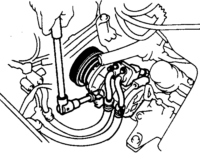
21. W/ A/C: REMOVE A/C COMPRESSOR WITHOUT DISCONNECTING HOSES
(a) Disconnect the A/C compressor connector.
(b) Remove the drive belt.
(c) Remove the 3 bolts, and disconnect the A/C compressor.
HINT: Put aside the compressor, and suspend it from the radiator support.
Pic 18
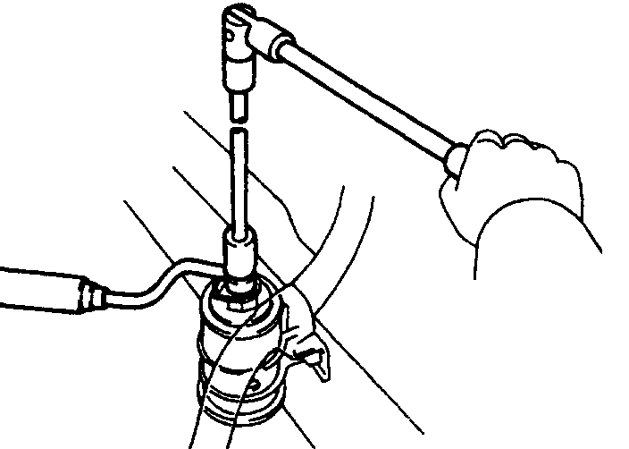
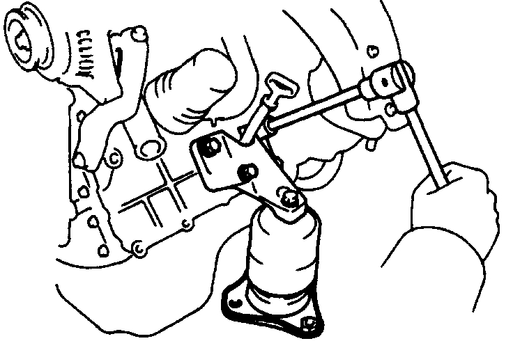
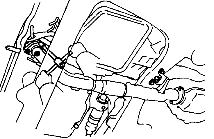
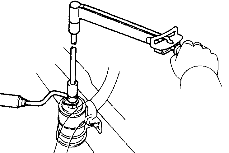
22. DISCONNECT FRONT EXHAUST PIPE
(a) Loosen the 2 bolts, and disconnect the bracket.
(b) Using a 14 mm deep socket wrench, remove the 3 nuts holding the front exhaust pipe to the WU-TWC.
(c) Disconnect the front exhaust pipe and gaskets.
23. REMOVE DRIVE SHAFTS
pic 19
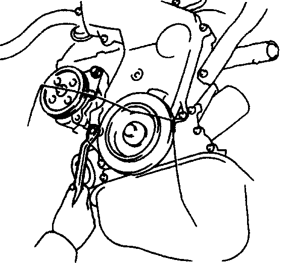
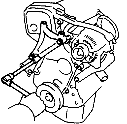
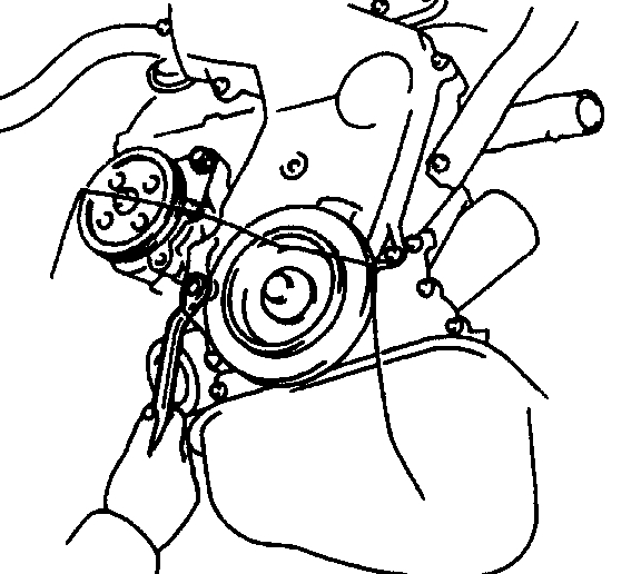
24. REMOVE PS PUMP WITHOUT DISCONNECTING HOSES
(a) Disconnect the 2 air hoses from the air pipe.
(b) Remove the PS drive belt.
(c) Remove the 2 bolts, and disconnect the PS pump from the engine.
HINT: Put aside the pump and suspend it from the cowl with a string.
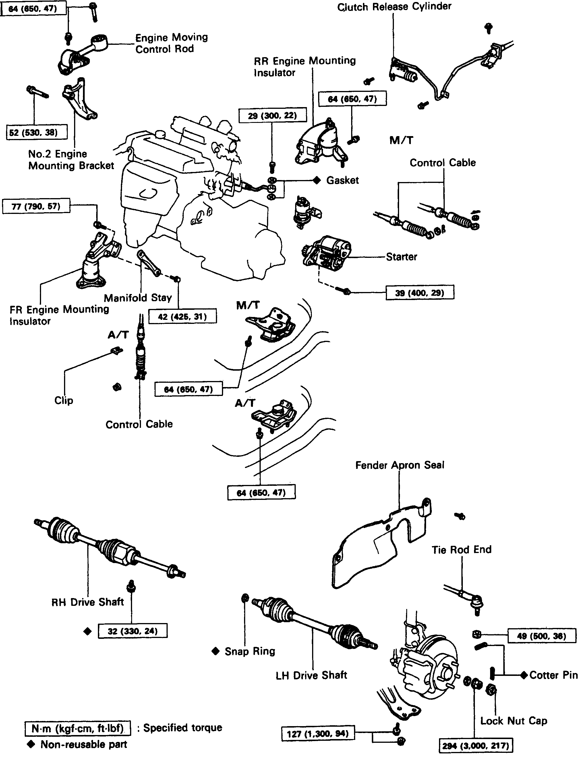
25. DISCONNECT LH ENGINE MOUNTING INSULATOR
pic 20
M/T: Remove the 3 bolts, and disconnect the mounting insulator.
Pic 21
A/T: Remove the 4 bolts, and disconnect the mounting insulator.
Pic 22
26. DISCONNECT RR ENGINE MOUNTING INSULATOR
(a) Remove the hole plugs.
(b) Remove the 3 nuts, and disconnect the mounting insulator.
Pic 23
27. DISCONNECT FR ENGINE MOUNTING INSULATOR
- Remove the 3 bolts, and disconnect the mounting insulator.
Pic 24
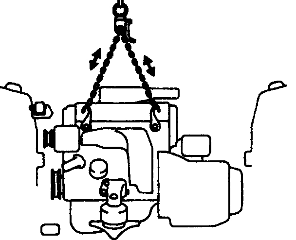
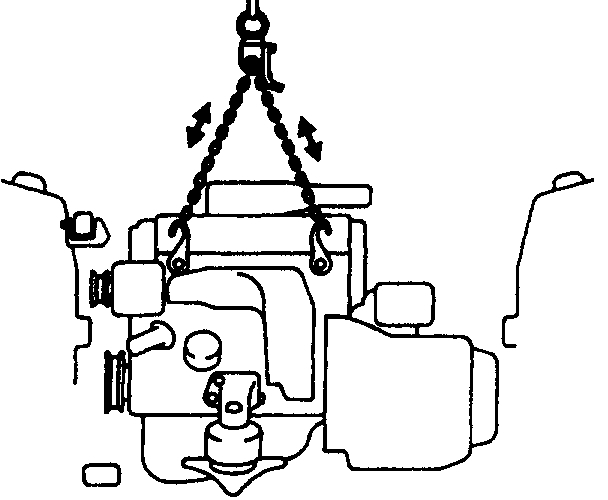
28. ATTACH ENGINE SLING DEVICE TO ENGINE HANGERS
pic 25
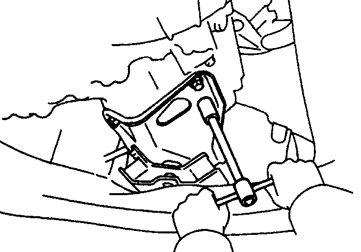
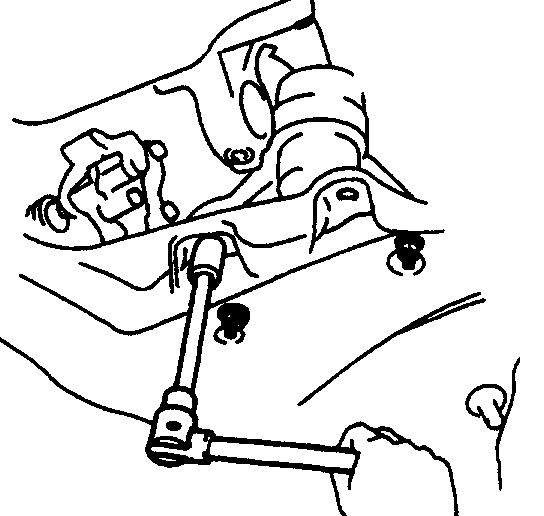
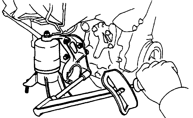
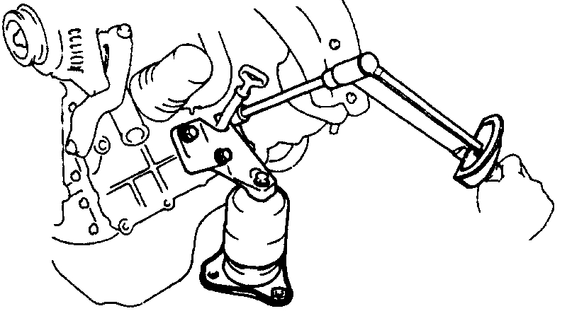
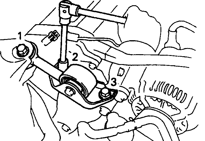
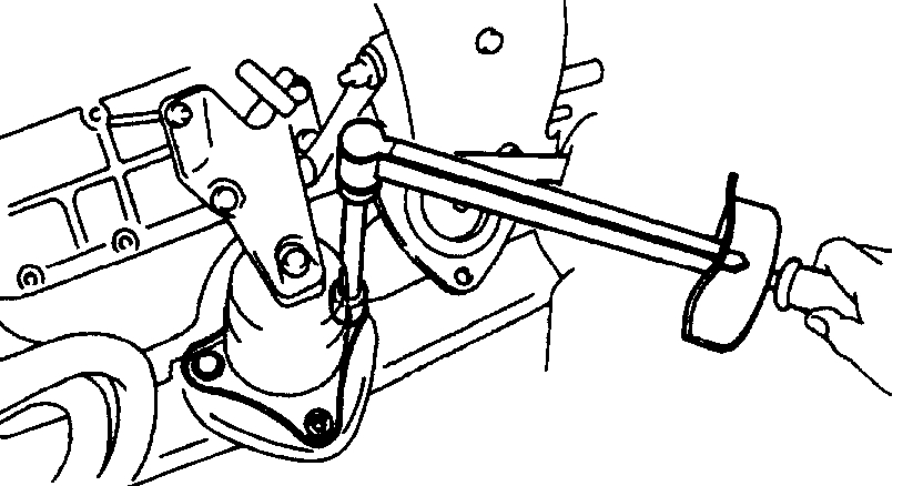
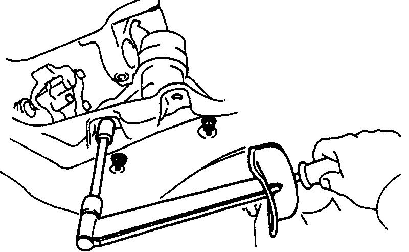
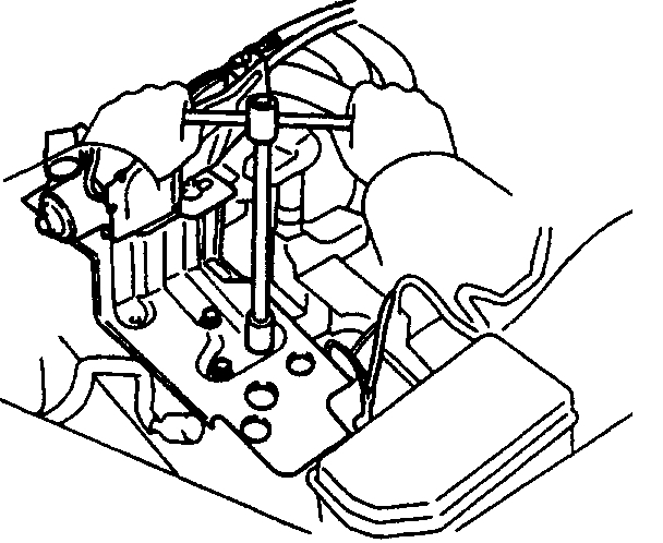
29. REMOVE ENGINE MOVING CONTROL ROD
- Remove the 3 bolts and control rod.
Pic 26
30. REMOVE ENGINE AND TRANSAXLE ASSEMBLY FROM VEHICLE
(a) Lift the engine out of the vehicle slowly and carefully.
NOTICE: Be careful not to hit the PS gear housing or park/neutral position switch (A/T).
(b) Make sure the engine is clear of all wiring, hoses and cables.
(c) Place the engine and transaxle assembly onto the stand.
31. A/T: REMOVE STARTER
32. SEPARATE ENGINE AND TRANSAXLE
pic 27
33. REMOVE NO.2 RH ENGINE MOUNTING BRACKET
- Remove the 3 bolts and engine mounting bracket.
Pic 28
34. REMOVE FR ENGINE MOUNTING INSULATOR
(a) Remove the bolt, nut and manifold stay.
(b) Remove the 4 bolts and mounting insulator.
Pic 29
35. REMOVE RR ENGINE MOUNTING INSULATOR
- Remove the 4 bolts and mounting insulator.
ENGINE INSTALLATION
pic 30
1. INSTALL RR ENGINE MOUNTING INSULATOR
- Install the mounting insulator with the 4 bolts.
Torque: 64 N.M (650 kgf. Cm, 47 ft. Lbf)
pic 31
2. INSTALL FR ENGINE MOUNTING INSULATOR
(a) Install the mounting insulator with the 4 bolts.
Torque: 77 N.M (790 kgf. Cm, 57 ft. Lbf)
(b) Install the manifold stay with the bolt and nut.
Torque: 42 N.M (425 kgf. Cm. 31 ft. Lbf)
3. INSTALL NO.2 ENGINE MOUNTING BRACKET
pic 32
(a) Temporarily install the No.2 engine mounting bracket with the 2 bolts.
Pic 33
(b) Install the remaining bolt.
(c) Tighten the 3 bolts in the sequence shown.
Torque: 52 N.M (530 kgf. Cm, 38 ft. Lbf)
4. ASSEMBLE ENGINE AND TRANSAXLE
5. A/T: INSTALL STARTER
pic 34
6. INSTALL ENGINE AND TRANSAXLE ASSEMBLY IN VEHICLE
(a) Attach the engine sling device to the engine hangers.
(b) Lower the engine into the engine compartment. Tilt the transaxle downward, lower the engine and clear the LH mounting.
NOTICE: Be careful not to hit the PS gear housing or park/neutral position switch (A/T).
Pic 35
(c) Keep the engine level, and align RH and LH mountings with the body bracket.
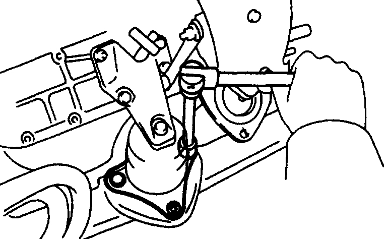
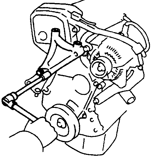
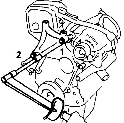
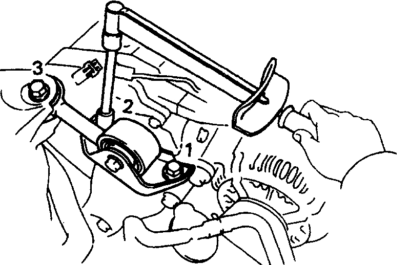
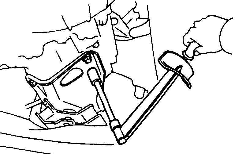
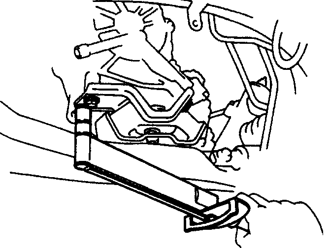
7. INSTALL ENGINE MOVING CONTROL ROD
pic 36
(a) Temporarily install the engine moving control rod with the 3 bolts in the sequence shown.
Image
(b) Tighten the 3 bolts in the sequence shown.
Torque: 64 N.M (650 kgf. Cm, 47 ft. Lbf)
pic 37
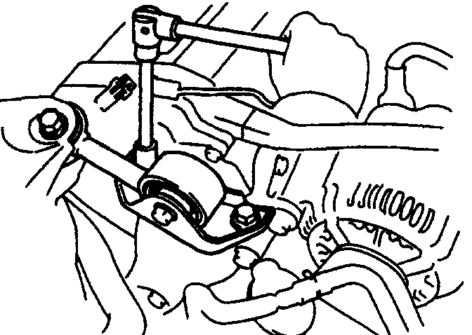
8. CONNECT FR ENGINE MOUNTING INSULATOR
- Connect the mounting insulator with the 3 bolts.
Torque: 80 N.M (820 kgf. Cm, 59 ft. Lbf)
pic 38
9. CONNECT RR ENGINE MOUNTING INSULATOR
(a) Connect the mounting insulator with the 3 nuts.
Torque: 66 N.M (670 kgl. Cm, 48 ft. Lbf)
(b) Install the hole plugs.
10. CONNECT LH ENGINE MOUNTING INSULATOR
pic 39
M/T: Connect the mounting insulator with the 3 bolts.
Torque: 64 N.M (650 kgf. Cm, 47 ft. Lbf)
pic 40
A/T: Connect the mounting insulator with the 4 bolts.
Torque: 64 N.M (650 kgf. Cm, 47 ft. Lbf)
11. REMOVE ENGINE SLING DEVICE
pic 41
12. INSTALL PS PUMP
(a) Install the PS pump with the 2 bolts.
Torque: 43 N.M (440 kgf. Cm, 31 ft. Lbf)
(b) Install the drive belt.
(c) Connect the 2 air hoses to the air pipe.
13. INSTALL DRIVE SHAFTS
pic 42
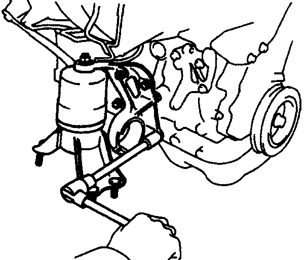
14. CONNECT FRONT EXHAUST PIPE
(a) Place a new gasket on the front exhaust pipe.
(b) Using a 14 mm deep socket wrench, install the three new nuts holding the front exhaust pipe to the exhaust manifold (three-way catalytic converter (front).
Torque: 62 N.M (630 kgf. Cm. 46 ft. Lbf)
(c) Install the bracket with the two bolts.
Pic 43
15. (W/ A/C) INSTALL A/C COMPRESSOR
(a) Install the compressor with the three bolts.
Torque: 27 N.M (280 kgf. Cm. 20 ft. Lbf)
(b) Install the drive belt.
(c) Connect the A/C compressor connector.
Pic 44
16. CONNECT ENGINE WIRE TO CABIN
(a) Push in the engine wire through the cowl panel. Install the two nuts.
(b) Connect the following connectors:
pic 45
(1) Two FCM connectors
(2) Four cowl wire connectors
(c) Install the glove compartment.
(d) Install the glove compartment door.
(e) Install the lower instrument panel.
(f) Install the under cover.
Pic 46
17. CONNECT VACUUM HOSES
(a) Vacuum sensor hose to air intake chamber
(b) Brake booster vacuum hose to air intake chamber
(c) Charcoal canister vacuum hose
pic 47
pic 48
18. CONNECT TRANSAXLE CONTROL CABLE(S) TO TRANSAXLE
pic 49
19. (M/T) INSTALL CLUTCH RELEASE CYLINDER
- Install the release cylinder and tube with the four bolts.
20. (M/T) INSTALL STARTER
pic 50
21. CONNECT FUEL INLET HOSE
Torque: 29 N.M (300 kgf. Cm, 22 ft. Lbf)
pic 51
22. CONNECT FUEL RETURN HOSE
23. CONNECT HEATER HOSES
24. CONNECT WIRES AND CONNECTORS
pic 52
(a) Connect the 5 connectors to the relay box.
(b) Connectors from LH fender apron.
(c) Install the engine relay box.
(d) Connect the following connectors:
pic 53
(1) Igniter connector
(2) California only: Ignition coil connector
(3) Noise filter connector
(4) 2 ground straps from LH fender apron
(5) Connector from LH fender apron
pic 54
(6) Data link connector 1
(7) 2 ground straps from RH fender apron
(e) Connect the MAP sensor connector.
25. INSTALL RADIATOR
pic 55
26. W/ CRUISE CONTROL SYSTEM: INSTALL CRUISE CONTROL ACTUATOR
(a) Install the actuator and bracket with the 3 bolts.
(b) Connect the actuator connector.
(c) Install the actuator cover.
Pic 56
27. INSTALL AIR CLEANER ASSEMBLY, RESONATOR AND AIR CLEANER HOSE
(a) Install the air cleaner case with 3 bolts.
(b) Install the element.
(c) Connect the air cleaner hose to the throttle body.
(d) Install the air cleaner cap together with the resonator and air cleaner hose.
(e) California only: Connect the air hose to the air cleaner hose.
(f) Connect the intake air temperature sensor connector.
28. A/T: CONNECT AND ADJUST THROTTLE CABLE
29. CONNECT AND ADJUST ACCELERATOR CABLE
30. FILL WITH ENGINE COOLANT
31. FILL WITH ENGINE OIL
Drain and Refill Capacity:
w/ Oil filter change: 3.6 liters (3.8 US qts)
w/o Oil filter change: 3.4 liters (3.6 US qts)
Dry Fill Capacity: 4.2 liters (4.4 US qts)
32. CONNECT NEGATIVE (-) TERMINAL CABLE TO BATTERY
33. START ENGINE AND CHECK FOR LEAKS
34. PREFORM ENGINE ADJUSTMENT
35. INSTALL ENGINE UNDER COVERS
36. INSTALL HOOD
37. PERFORM ROAD TEST
- Check for abnormal noises, shock, slippage, correct shift points and smooth operation.
38. RECHECK ENGINE COOLANT AND ENGINE OIL LEVELS
__________________________
Hope this helps. Let me know your plans.
Take care,
Joe
Images (Click to make bigger)
Monday, February 24th, 2020 AT 8:04 PM