Hi. No, there is no cost. We are here to help when we can.
Okay, here we go. I am going to first provide directions for removing the heads. After this process, I will then add the timing chains. The pictures I attach (and there are many) will correlate with the directions.
____________________________________________________________
Cylinder Head LH (12.29.02)
Removal
Vehicles with 2.5L or 3.0L engine
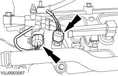
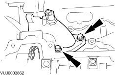
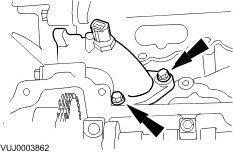
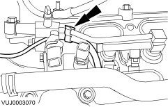
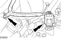
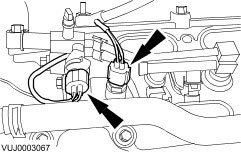
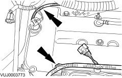
1. Disconnect the engine coolant temperature (ECT) and fuel temperature sensor (FTS) electrical connectors.
2. Disconnect the electrical connector.
3. Detach fuel sensor vacuum line.
Vehicles with 2.0L engine
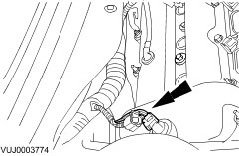
4. Disconnect the coolant temperature (ECT) electrical connector.
All vehicles
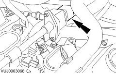
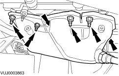
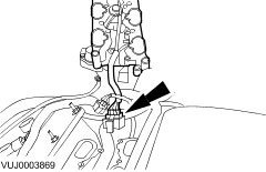
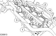
5. Detach the fuel charging wiring harness.
- 2.5 and 3.0L shown, 2.0L similar.
6. WARNING: Fuel may still be present in the fuel injection supply manifold, extreme care must be taken as this could cause personal injury.
Detach the fuel injection supply manifold, lower intake manifold and place to one side.
- Remove and discard the lower intake manifold seals.
* 2.5 and 3.0L shown, 2.0L similar.
7. Remove the fuel injection supply manifold and lower intake manifold.
- Disconnect the electrical connector.
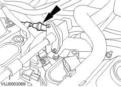
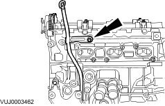
8. Remove the oil level indicator tube.
- Remove and discard the oil level indicator tube O-ring seal.
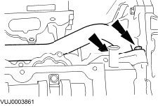
9. Remove the water pump outlet pipe.
- Remove and discard the water pump outlet pipe O-ring seals.
10. Remove the coolant bypass tube.
- Remove and discard the coolant bypass tube O-ring seals.
11. Remove the exhaust manifold.
- Remove and discard the exhaust manifold gasket.
12. Remove the left-hand camshafts.
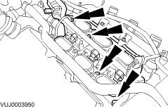
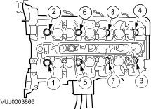
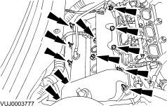
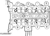
13. NOTE: Remove the bolts in the indicated sequence.
Remove the cylinder head.
- Remove and discard the cylinder head gasket.
14. Clean and inspect the cylinder head and cylinder block.
_________________________________
Installation
All vehicles
1. NOTE: The head gaskets must be installed over the cylinder block dowels.
Install a new cylinder head gasket.
2. CAUTION: Use care when installing the cylinder head. Damage to the cylinder block, cylinder head or the cylinder head gasket may result.
NOTE: Make sure the cylinder head is installed in its original position.
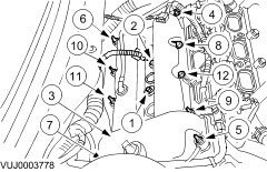
NOTE: Tighten the bolts in the indicated sequence in six stages.
Position the cylinder head and install new cylinder head bolts and washers.
- Stage 1: Tighten to 30 Nm.
- Stage 2: Tighten 90 degrees.
- Stage 3: Loosen 360 degrees (one full turn) in reverse order.
- Stage 4: Tighten to 30 Nm.
- Stage 5: Tighten 90 degrees.
- Stage 6: Tighten 90 degrees.
3. Install the left-hand camshafts.
4. Install the exhaust manifold.
- Install the new exhaust manifold gasket.
- Complete the tightening sequence.
- Tighten to 20 Nm.
5. Install the coolant bypass tube.
- Install the new coolant bypass tube O-ring seals.
- Tighten to 10 Nm.
6. Install the water pump outlet pipe.
- Install the new water pump outlet pipe O-ring seals.
- Tighten to 10 Nm.
7. Install the oil level indicator tube.
- Install a new O-ring seal.
- Tighten to 10 Nm.
8. Attach the fuel injection supply manifold and lower intake manifold.
- Connect the electrical connector.
9. Install the fuel injection supply manifold, lower intake manifold.
- Install new lower intake manifold O-ring seals.
- Tighten in the sequence shown.
- Tighten to 10 Nm.
10. Attach the fuel charging wiring harness.
- 2.5 and 3.0L shown, 2.0L similar.
Vehicles with 2.0L engine
11. Connect the coolant temperature (ECT) electrical connector.
Vehicles with 2.5L or 3.0L engine
12. Attach the fuel sensor vacuum line.
13. Connect the electrical connector.
14. Connect the engine coolant temperature (ECT) and fuel temperature sensor (FTS) electrical connectors.
______________________________________________
Valve Cover RH (12.29.44) (Pics 25 -30)
Removal
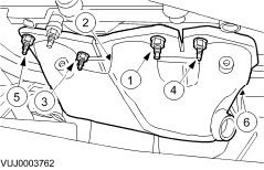
1. Remove the ignition coils.
2. Detach the wiring harness.
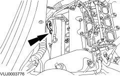
3. Disconnect the variable camshaft timing (VCT) solenoid electrical connector.
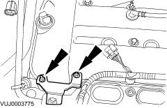
4. Remove the engine cover retaining bracket.
5. Remove the intake manifold support bracket.
6. Remove the valve cover.
- Remove and discard the valve cover gaskets.
Installation
1. NOTE: Apply a 5 mm diameter bead of silicone gasket sealant WSE-M4G323-A6 or equivalent meeting Jaguar specification on the half round gaskets and apply an 8 mm diameter bead of silicone gasket sealant on the two places where the cylinder head and front timing cover join.
NOTE: Make sure that the valve cover isolator mounts are correctly installed to the new valve cover gaskets.
To install, reverse the removal procedure.
- Install the new valve cover gaskets.
- Complete the tightening sequence.
- Tighten to 10 Nm.
2. Tighten to 6 Nm.
3. Tighten to 6 Nm.
______________________________________________________________
Timing Chain (remaining pics)
TIMING DRIVE COMPONENTS 12.65.13
Timing Drive Components (12.65.13)
Removal
1. Remove the engine front cover.
2. Remove the spark plugs.
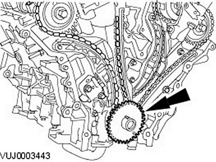
3. NOTE: Note the position of the crankshaft position (CKP) sensor pulse wheel during removal. It must be returned to its original position during installation.
Remove the crankshaft position (CKP) sensor pulse wheel.
4. CAUTION: Do not rotate the crankshaft counterclockwise. The timing chains may bind causing engine damage.
Install the crankshaft pulley retaining bolt and washer.
5. CAUTION: Do not rotate the crankshaft counterclockwise. The timing chains may bind causing engine damage.
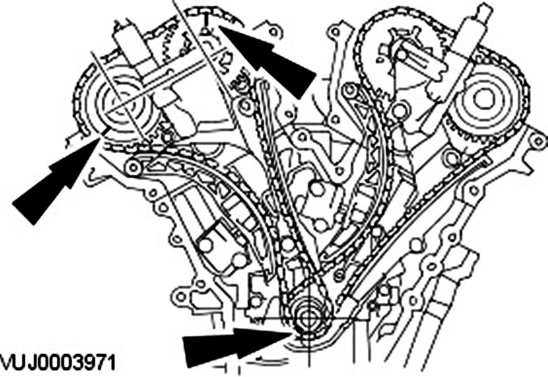
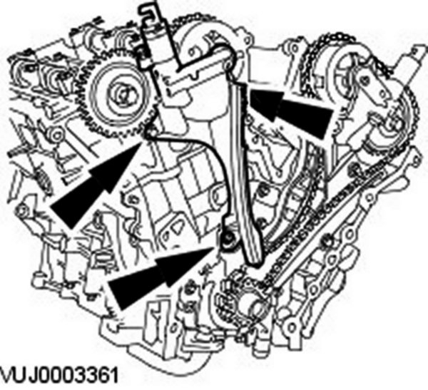
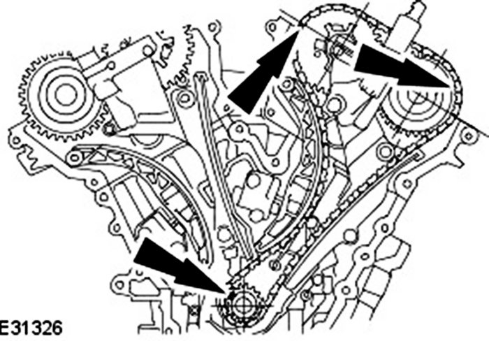
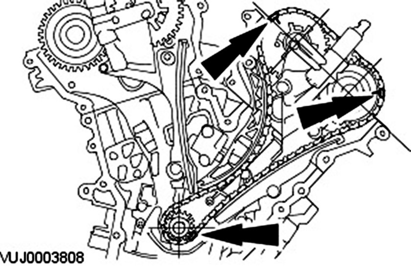
Rotate the crankshaft clockwise until the crankshaft keyway is at the 7 O'clock position, the alignment mark on the right-hand intake camshaft sprocket is at the 1 O'clock position and the alignment mark on the right-hand exhaust camshaft sprocket is at the 8 O'clock position.
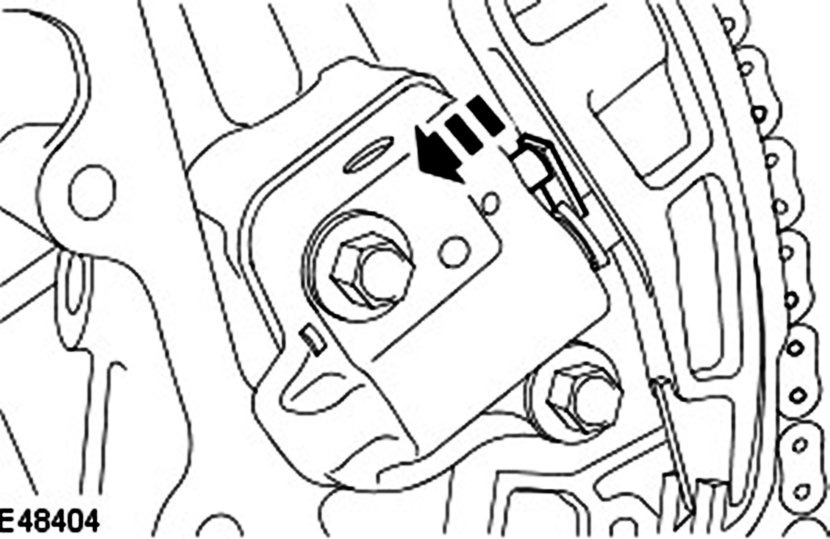
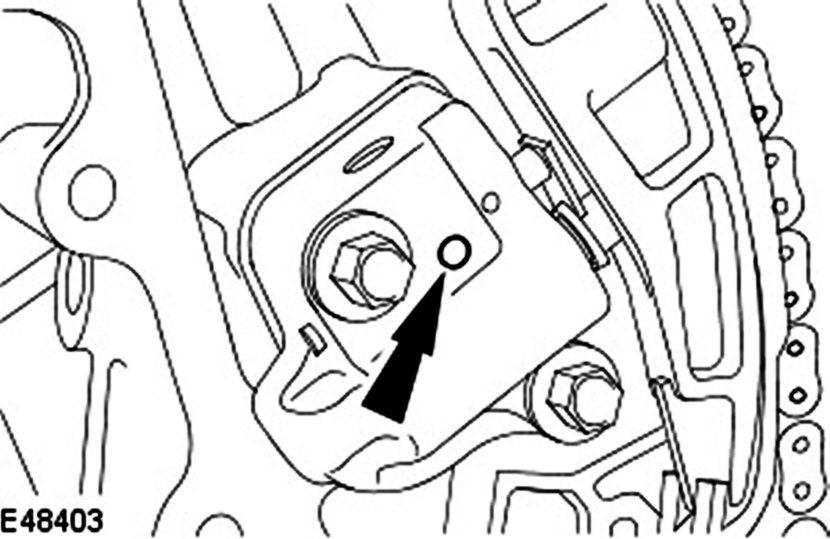
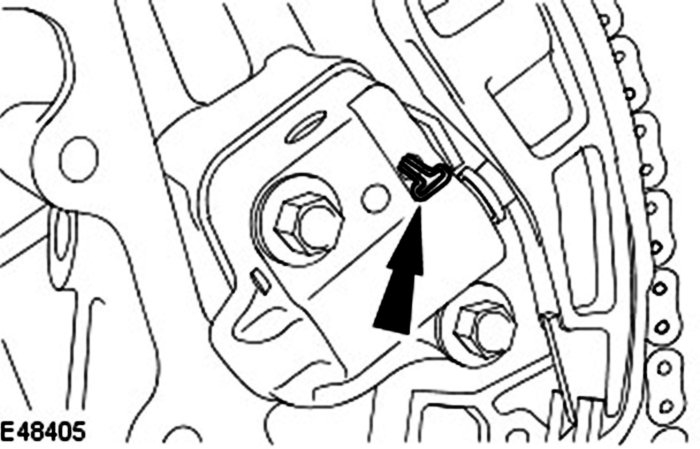
6. Release the timing chain tensioner ratchet.
7. NOTE: Keep the timing chain tensioner ratchet released.
Reposition the timing chain tensioner plunger.
8. Retain the timing chain tensioner plunger.
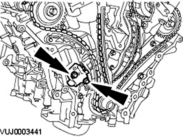
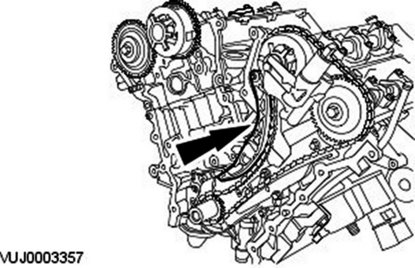
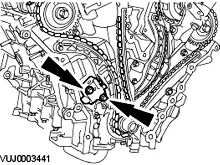
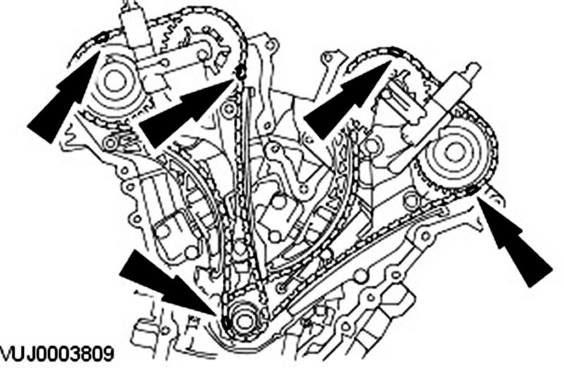
9. Remove the right-hand timing chain tensioner.
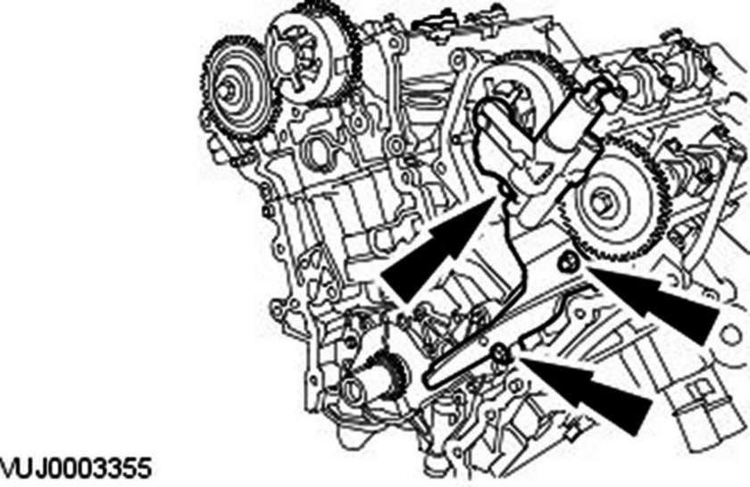
10. Remove the right-hand timing chain outer guide.
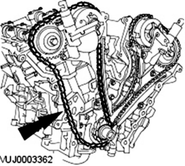
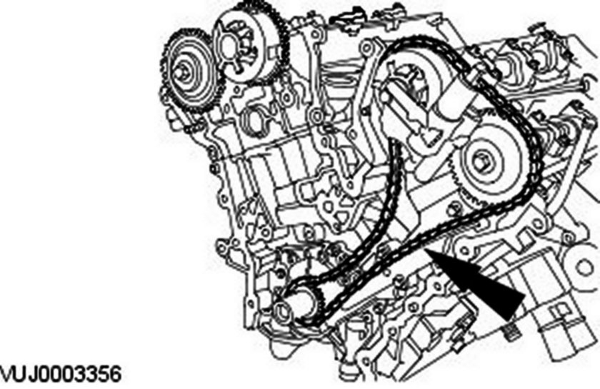
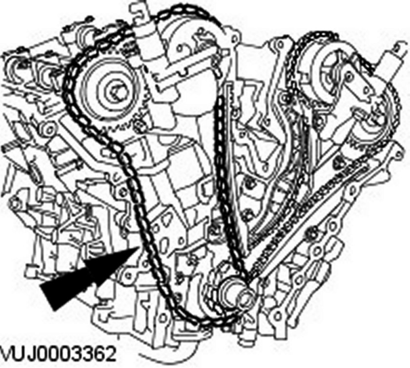
11. Remove the right-hand timing chain.
12. CAUTION: Inspect and replace the O-ring seal if necessary.
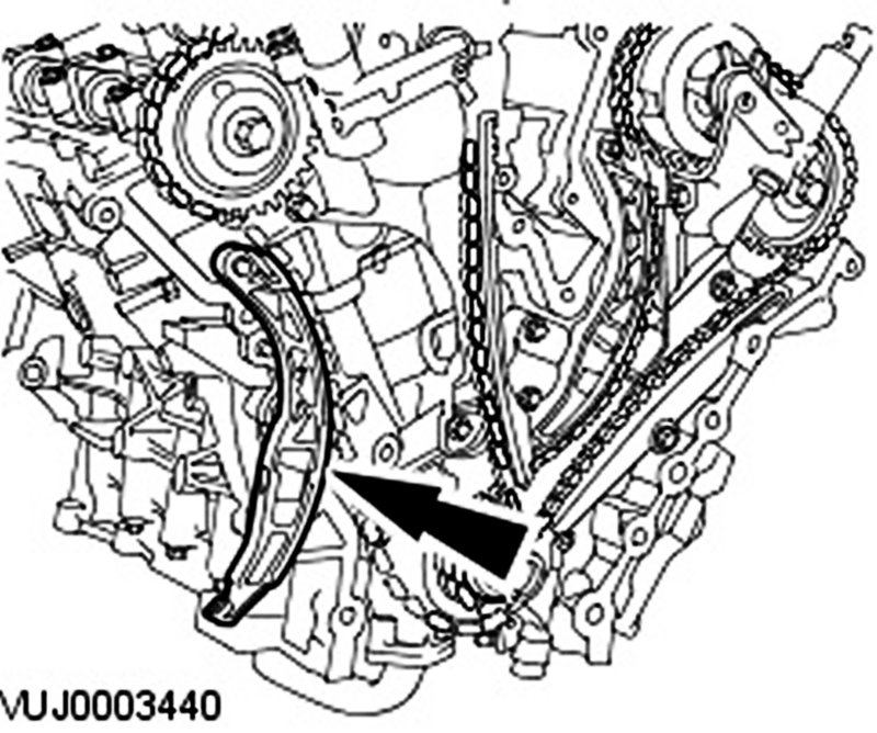
Remove the right-hand timing chain inner guide.
13. CAUTION: Do not rotate the crankshaft counterclockwise. The timing chains may bind causing engine damage.
Rotate the crankshaft clockwise until the crankshaft keyway is at the 11 O'clock position, the alignment mark on the lefthand intake camshaft sprocket is at the 9 O'clock position and the alignment mark on the left-hand exhaust camshaft sprocket is at the 2 O'clock position.
14. NOTE: Right-hand bank shown, left-hand bank similar.
Release the timing chain tensioner ratchet.
15. NOTE: Right-hand bank shown, left-hand bank similar.
NOTE: Keep the timing chain tensioner ratchet released.
Reposition the timing chain tensioner plunger.
16. NOTE: Right-hand bank shown, left-hand bank similar.
Retain the timing chain tensioner plunger.
17. Remove the left-hand timing chain tensioner.
18. Remove the left-hand timing chain inner guide.
19. Remove the left-hand timing chain.
20. CAUTION: Inspect and replace the O-ring seal if necessary.
Remove the left-hand timing chain outer guide.
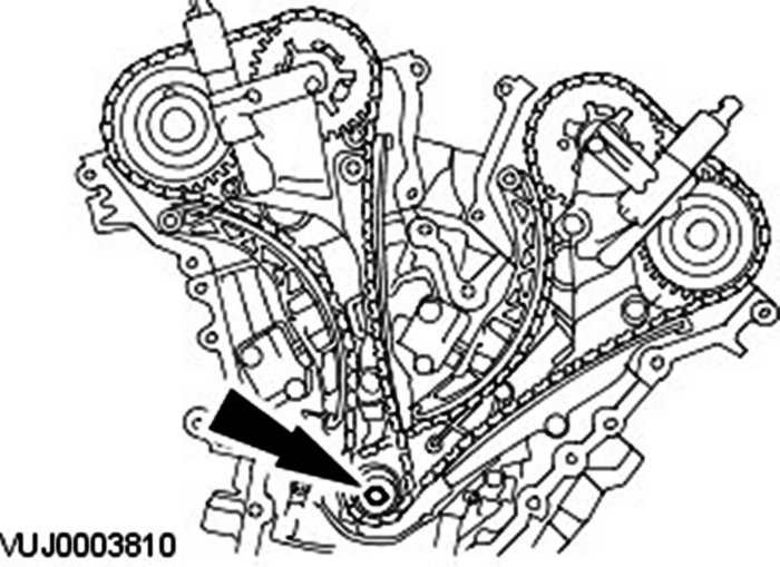
21. CAUTION: Make sure the crankshaft keyway is at the 9 O'clock position before any further engine repairs are carried out.
Remove the crankshaft pulley retaining bolt and washer.
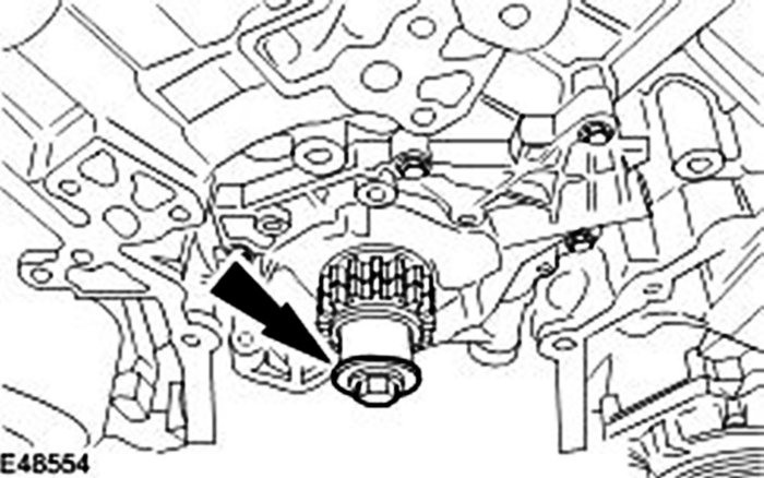
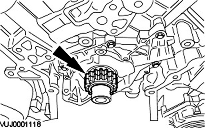
22. Remove the crankshaft sprocket.
_______________________________________
Installation
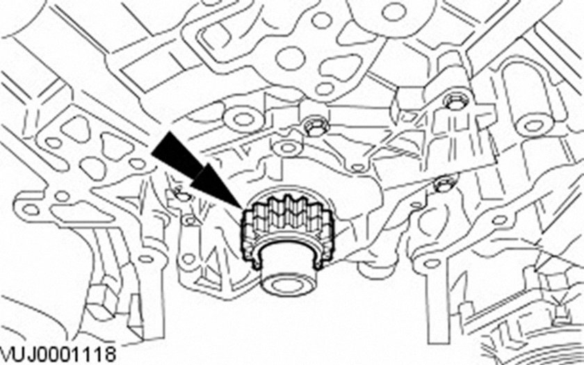
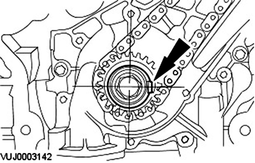
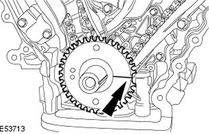
1. NOTE: Make sure the crankshaft sprocket timing marks are facing outwards.
Install the crankshaft sprocket.
2. CAUTION: Make sure the crankshaft keyway is at the 9 O'clock position before the camshaft positions are aligned.
Install the crankshaft pulley retaining bolt and washer.
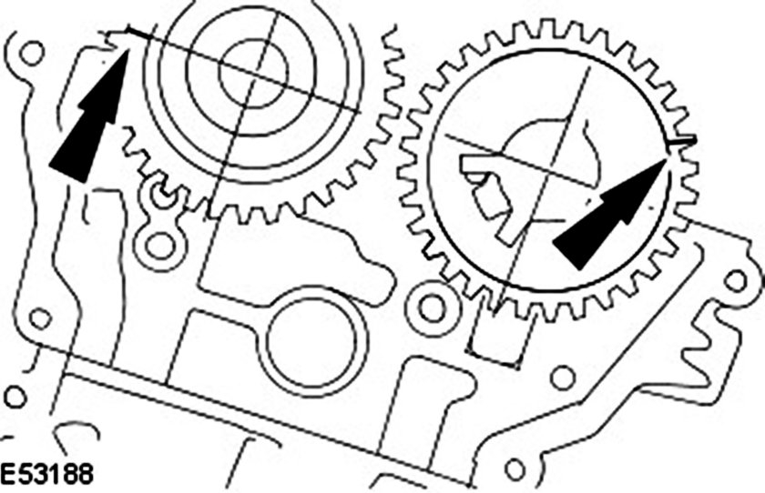
3. Rotate the left-hand intake camshaft clockwise until the camshaft sprocket alignment mark is at the 9 O'clock position and rotate the left-hand exhaust camshaft sprocket clockwise until the camshaft sprocket alignment mark is at the 2 O'clock position.
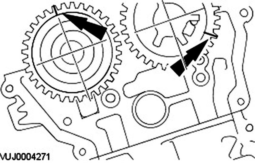
4. Rotate the right-hand intake camshaft clockwise until the camshaft sprocket alignment mark is at the 5 O'clock position and rotate the right-hand exhaust camshaft sprocket clockwise until the camshaft sprocket alignment mark is at the 12 O'clock position.
5. Rotate the crankshaft clockwise until the keyway is at the 11 O'clock position.
6. CAUTION: Inspect and replace the O-ring seal if necessary.
CAUTION: Make sure the O-ring seal is correctly installed.
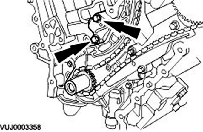
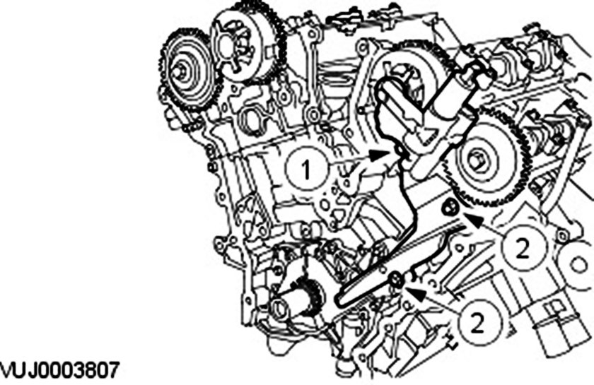
Install the left-hand timing chain outer guide.
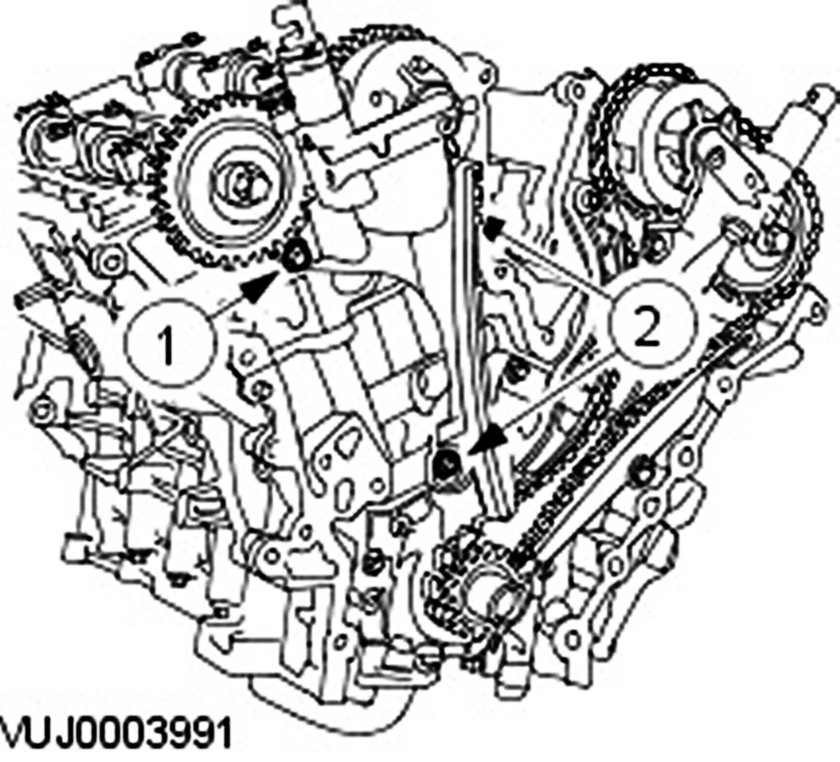
- Tighten the retaining bolts in the sequence shown in two stages.
- Stage 1: Tighten bolt 1 to 25 Nm.
- Stage 2: Tighten bolts 2 to 25 Nm.
7. CAUTION: Make sure the crankshaft keyway is at the 11 O'clock position, the alignment mark on the left-hand intake camshaft sprocket is at the 9 O'clock position and the alignment mark on the left-hand exhaust camshaft sprocket is at the 2 O'clock position.
8. CAUTION: Make sure the timing chain alignment marks are correctly positioned to the crankshaft sprocket and camshaft sprocket alignment marks.
9. CAUTION: Make sure the timing chain slack is on the tensioned side of the timing chain.
Install the left-hand timing chain.
8. Install the left-hand timing chain inner guide.
9. CAUTION: Do not manually adjust the timing chain tensioner.
Install the left-hand timing chain tensioner.
- Tighten to 25 Nm.
10. CAUTION: Do not manually adjust the timing chain tensioner.
Make sure the left-hand timing chain alignment marks have remained correctly positioned to the camshaft sprocket and crankshaft sprocket alignment marks.
11. CAUTION: Do not manually adjust the timing chain tensioner.
Remove the timing chain tensioner retaining pin.
12. CAUTION: Do not rotate the crankshaft counterclockwise. The timing chains may bind causing engine damage.
Rotate the crankshaft clockwise until the crankshaft keyway is at the 3 O'clock position.
13. CAUTION: Inspect and replace the O-ring seal if necessary.
CAUTION: Make sure the O-ring seal is correctly installed.
Install the right-hand timing chain inner guide.
- Tighten the retaining bolts in the sequence shown in two stages.
- Stage 1: Tighten bolt 1 to 25 Nm.
- Stage 2: Tighten bolts 2 to 25 Nm.
14. CAUTION: Make sure the crankshaft keyway is at the 3 O'clock position, the alignment mark on the right-hand intake camshaft sprocket is at the 5 O'clock position and the alignment mark on the right-hand exhaust camshaft sprocket is at the 12 O'clock position.
CAUTION: Make sure the timing chain alignment marks are correctly positioned to the crankshaft sprocket and camshaft sprocket alignment marks.
CAUTION: Make sure the timing chain slack is on the tensioned side of the timing chain.
Install the right-hand timing chain.
15. Install the right-hand timing chain outer guide.
16. CAUTION: Do not manually adjust the timing chain tensioner.
Install the right-hand timing chain tensioner.
- Tighten to 25 Nm.
17. CAUTION: Do not manually adjust the timing chain tensioner.
Remove the timing chain tensioner retaining pin.
18. CAUTION: Make sure the right-hand timing chain alignment marks have remained correctly positioned to the camshaft sprocket and crankshaft sprocket alignment marks.
CAUTION: Do not manually adjust the timing chain tensioner.
Make sure all the timing chain alignment marks are in the positions shown.
19. CAUTION: Do not rotate the crankshaft counterclockwise. The timing chains may bind causing engine damage.
NOTE: Rotate the crankshaft using hand tools only.
Rotate the crankshaft two complete turns clockwise to make sure the valves and pistons do not clash.
20. CAUTION: Do not rotate the crankshaft counterclockwise. The timing chains may bind causing engine damage.
Remove the crankshaft pulley retaining bolt and washer.
21. CAUTION: Make sure the CKP sensor pulse wheel is correctly installed with the missing tooth aligned to the crankshaft keyway.
CAUTION: Make sure the CKP sensor pulse wheel is correctly installed with the teeth pointing outwards.
Install the CKP sensor pulse wheel.
22. Install the spark plugs.
- Tighten to 15 Nm.
23. Install the engine front cover.
______________________________________________
Ugh! That is a lot. I pray I did not miss anything.
Let me know how things work out for you.
Take care,
Joe
Images (Click to enlarge)
Aug 3, 2018 at 7:02 PM