Removing stuff is not a good way to check voltages, especially in this circuit. If you're going to do that, use a test light instead of a digital voltmeter. That has to be the old-style test light with an incandescent bulb inside, not one of the newer type with electronics built in.
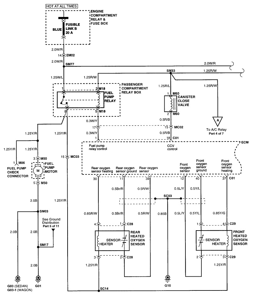
This doesn't apply to this problem, but if you look at the top of the diagram, you'll see "fuse link B" shown as feeding the fuel pump relay. That term is used by some manufacturers to denote a large fuse, but really that term means it's a fuse link wire. Those are never intermittent. If they're good, they act like a wire when you tug on them gently. If they're burned open, they act like a rubber band. Where even very experienced mechanics become confused is when a fuse link wire burns open, it arcs as it burns away and leaves a carbon track behind on the inside of the insulation. No current can get through to run the fuel pump, however, if you remove the relay, (or unplug the pump), a digital voltmeter will falsely "see" 12 volts. That carbon track can conduct just enough current for the meter to detect some voltage.
Voltmeters work by measuring electrical pressure, (voltage), just like a pressure gauge reads pressure on a compressed air line. No air actually flows through the gauge. No current flows through the voltmeter. A pipe on a compressed air system can be 99 percent blocked, and the gauge will still see full pressure at the end of the line, . . . as long as you aren't trying to run an air tool. As soon as you do, the pressure will drop to almost 0 psi. Same with the burned fuse link wire. The meter will see the 12 volts further down the line, until you try to use some current. That's when it will drop to 0 volts.
The test light works by having current flow through it. Since that can't happen with a burned fuse link wire, it will accurately show 0 volts.
Again, that sad story doesn't apply here because your fuel pump runs at times. Since fuses can't be intermittent and only work part of the time, yours has to be okay. The only exceptions are when there's a lot of corrosion on the terminals of a plug-in fuse, or when the fuse device is an auto-resetting thermal circuit breaker. Those can develop pitting or arcing on the contact points that prevents them from making a good contact and passing current.
Most of the time when we read about intermittent crank / no-starts, it involves a loss of fuel and spark at the same time, so don't overlook checking for spark. Not to confuse the issue unnecessarily, but that typically involves loss of signal pulses from the crankshaft position sensor or the camshaft position sensor. One clue is you still get that initial hum of the fuel pump for one second when you turn on the ignition switch. The pump fails to resume running when the engine is rotating, (cranking or running). Since you don't hear that hum for the initial one second, we may have to look in a different direction.
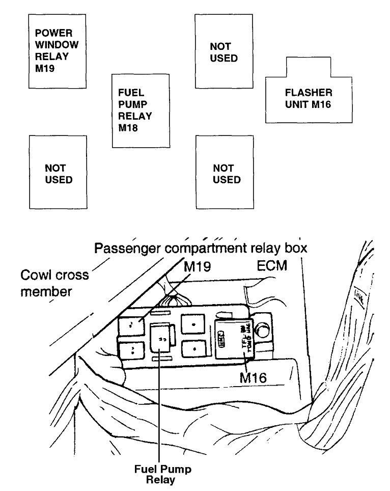
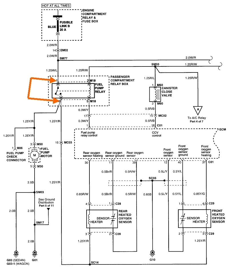
For now, a better way to test the fuel pump circuit is to bypass the relay. This will power up the pump without the need to turn on the ignition switch. The contact terminals are pointed out with my orange arrows. Use a pair of generic spade terminals in the relay socket for the two terminals shown. Be careful that those terminals aren't fatter than those on the relay. Anything too fat can spread the terminals in the socket leading to intermittent connection problems later. Use a small jumper wire to connect the two terminals. You can also do this with a stretched-out paper clip or any other piece of wire.
Another way to do this is to remove the cover from the relay, (some are easy to do, while others are almost impossible), install it that way, then squeeze the movable contact. Some relay designs allow you to place a rubber band around it to keep the movable contact turned on.
Once the pump is running, you can wiggle wires and take voltage readings in the circuit. When you get to the ground circuits, voltage readings are still the best way to diagnose a problem. Set your meter to its lowest DC volts scale for the most accuracy. It's normal to find a few hundredths of a volt due to normal resistance in a wire, but anything over roughly a few tenths of a volt points to a connection that needs attention.
Most competent do-it-yourselfers try to take continuity, or resistance readings in ground circuits but that too leads to false results. All it takes is one tiny strand of wire that isn't yet corroded off for an ohm meter to show good continuity, or close to 0 ohms. There's no way the current needed to run a pump motor can get through that one strand of wire. This is where the excessive "voltage drop" will show up with the voltage test. The resistance in that part of the circuit is way too small to measure, but we can measure the RESULTS of that resistance with the voltage readings.
Please keep me updated with your progress.
Images (Click to enlarge)
May 8, 2023 at 4:06 PM