If it's the blend door actuator, it should set a 24 or 25 code. What are your symtoms? You can check the door operation this way.
A/C-HEATER SYSTEM -1998 Lincoln Mark VIII
Page 1 of 3
DTC B1249 TEST: BLEND DOOR FAILURE
1. Check Actuator Clockwise Operation (Full Cool)
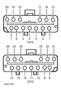
Turn ignition off. Disconnect EATC module connectors. Connect jumper wire between EATC connector C272 terminals No. 13 (Brown/Light Green wire) and No. 24 (Red wire). Connect a second jumper wire between EATC connector C272 terminals No. 26 (Purple wire) and No. 11 (Black wire). See Fig. 4 . If blend door actuator motor moves clockwise, go to next step. If blend door actuator motor does not move clockwise, go to step 3).
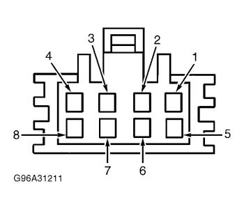
Fig. 4: Identifying Electronic Automatic Temperature Control (EATC) Module Connector Terminals
Courtesy of FORD MOTOR CO.
Fig. 5: Identifying Blend Door Actuator Connector Terminals Courtesy of FORD MOTOR CO.
2. Check Actuator Counterclockwise Operation (Full Hot)
Connect a jumper wire between EATC connector C272 terminals No. 26 (Purple wire) and No. 24 (Red wire). Connect second jumper wire between EATC connector C272 terminals No. 13 (Brown/Light Green wire) and No. 11 (Black wire). See Fig. 4 . If blend door actuator motor moves counterclockwise, go to step 7). If blend door actuator motor does not move counterclockwise, go to next step.
3. Check Purple Wire For Short
Disconnect electronic blend door actuator connector. With an ohmmeter, measure resistance between ground and EATC connector C272 terminal No. 26 (Purple wire). See Fig. 4 . If resistance is greater than 10,000 ohms, go to next step. If resistance is not greater than 10,000 ohms, repair short to ground in Purple wire.
4. Check Brown/Light Green Wire For Short
Measure resistance between ground and EATC connector C272 terminal No. 13 (Brown/Light Green wire). See Fig. 4 . If resistance is greater than 10,000 ohms, go to next step. If resistance is not greater than 10,000 ohms, repair short to ground in Brown/Light Green wire.
5. Check Purple Wire For Open
Measure resistance between EATC connector C272 terminal No. 26 (Purple wire) and blend door actuator connector terminal No. 8 (Purple wire). See Fig. 4 and Fig. 5 . If resistance is less than 5 ohms, go to next step. If resistance is not less than 5 ohms, repair open in Purple wire.
6. Check Brown/Light Green Wire For Open
Measure resistance between EATC connector C272 terminal No. 13 (Brown/Light Green wire) and blend door actuator connector terminal No. 7 (Brown/Light Green wire). See Fig. 4 and Fig. 5 . If resistance is less than 5 ohms, go to next step. If resistance is not less than 5 ohms, repair open in Brown/Light Green wire and retest system.
9/21/2008
A/C-HEATER SYSTEM -1998 Lincoln Mark VIII
Page 2 of 3
7. Check Actuator Operation
Remove electronic blend door actuator. See TEMPERATURE BLEND DOOR ACTUATOR in REMOVAL & INSTALLATION. Attach electronic blend door connector. With actuator drive shaft disengaged from temperature blend door, connect jumper wires, as in step 1), and drive electronic blend door full clockwise. Change jumper wire positions, as in step 2), and drive electronic blend door full counterclockwise. If electronic blend door actuator moved fully in both directions, repair temperature blend door for blocked or binding condition and retest system. If door did not move as indicated, replace electronic blend door actuator and retest system.
8. Check Feedback Potentiometer Resistance
Disconnect EATC connector C273. Following instructions in step 2), drive blend door actuator fully counterclockwise. With blend door actuator in fully counterclockwise position, measure resistance between EATC connector terminals No. 17 (Red/Light Green) and No. 4 (Red/White wire). See Fig. 4 . If resistance is 5,000-7,000 ohms, go to step 13). If resistance is not 5,000-7,000 ohms, go to next step.
9. Check Red/Light Green Wire For Open
Disconnect blend door actuator connector. Measure resistance between EATC connector C273 terminal No. 17 (Red/Light Green wire) and blend door actuator connector terminal No. 5 (Red/Light Green wire). See Fig. 4 and Fig. 5 . If resistance is less than 5 ohms, go to next step. If resistance is not less than 5 ohms, repair open in Red/Light Green wire. Retest system.
10. Check Red/White Wire For Open
Measure resistance between EATC connector C273 terminal No. 4 (Red/White wire) and blend door actuator connector terminal No. 6 (Red/White wire). See Fig. 4 and Fig. 5 . If resistance is less than 5 ohms, go to next step. If resistance is not less than 5 ohms, repair open in Red/White wire. Retest system.
11. Check Red/Light Green Wire For Short
Measure resistance between EATC module connector C273 terminal No. 17 (Red/Light Green wire) and ground. If resistance is more than 10,000 ohms, go to next step. If resistance is less than 10,000 ohms, repair short to ground in Red/Light Green wire and retest system.
12. Check Red/White Wire For Short
Measure resistance between EATC module connector C273 terminal No. 4 (Red/White wire) and ground. See Fig. 4 . If resistance is more than 10,000 ohms, replace electronic blend door and retest system. If resistance is less than 10,000 ohms, repair short to ground in Red/White wire and retest system.
13. Check Feedback Potentiometer Low Side Resistance
Following instructions in step 2), drive blend door actuator fully counterclockwise. With blend door actuator in fully counterclockwise position, measure resistance between EATC connector C273 terminals No. 3 (Yellow/Light Green) and No. 4 (Red/White wire). See Fig. 4 . If resistance
9/21/2008
A/C-HEATER SYSTEM -1998 Lincoln Mark VIII
Page 3 of 3
is 250-1,500 ohms, go to step 16). If resistance is not 250-1,500 ohms, go to next step.
14. Check Yellow/Light Green Wire For Open
Disconnect electronic blend door actuator connector. Measure resistance between EATC connector C273 terminal No. 3 (Yellow/Light Green wire) and blend door actuator connector terminal No. 1 (Yellow/Light Green wire). See Fig. 4 and Fig. 5 . If resistance is less than 5 ohms, go to next step. If resistance is not less than 5 ohms, repair open in Yellow/Light Green wire. Retest system.
15. Check Yellow/Light Green Wire For Short
Measure resistance between EATC module C273 terminal No. 3 (Yellow/Light Green wire) and ground. See Fig. 4 . If resistance is more than 10,000 ohms, replace electronic blend door actuator and retest system. If resistance is less than 10,000 ohms, repair short to ground in Yellow/Light Green wire and retest system.
16. Check Feedback Potentiometer High Side Resistance
Following instructions in step 2), drive blend door actuator fully counterclockwise. With blend door actuator in fully counterclockwise position, measure resistance between EATC connector C273 terminals No. 17 (Red/Light Green) and No. 3 (Yellow/Light Green wire). See Fig. 4 . If resistance is 3,500-6,000 ohms, go to next step. If resistance is not 3,500-6,000 ohms, replace electronic blend door actuator. Retest system.
17. Check Red/Light Green Wire For Short
Measure resistance between EATC connector C273 terminal No. 17 (Red/Light Green wire) and ground. See Fig. 4 . If resistance is greater than 10,000 ohms, go to next step. If resistance is not greater than 10,000 ohms, repair short to ground in Red/Light Green wire. Retest system.
18. Check Red/White Wire For Short
Measure resistance between EATC connector C273 terminal No. 4 (Red/White wire) and ground. See Fig. 4 . If resistance is greater than 10,000 ohms, go to next step. If resistance is not greater than 10,000 ohms, repair short to ground in Red/White wire. Retest system.
19. Check Yellow/Light Green Wire For Short
Measure resistance between EATC connector C273 terminal No. 3 (Yellow/Light Green wire) and ground. See Fig. 4 . If resistance is greater than 10,000 ohms, replace EATC module. Retest system. If resistance is not greater than 10,000 ohms, repair short to ground in Yellow/Light Green wire. Retest system.
9/21/2008
This is how to remove the instrument panel, then remove the ctuator from the back of the plenum.
A/C-HEATER SYSTEM -1998 Lincoln Mark VIII
Page 1 of 1
INSTRUMENT PANEL
Removal & Installation
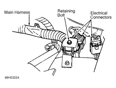
1.Disable air bag system. See AIR BAG RESTRAINT SYSTEM article. See AIR BAG RESTRAINT SYSTEM article. Disconnect negative battery cable. Raise vehicle on hoist. Disconnect transmission wiring harness on transmission crossmember. 2.Lower vehicle. Disconnect bulkhead electrical connectors. See Fig. 11 . Remove left bulkhead electrical connector. Unclip left bulkhead connector from dash panel.
Fig. 11: Disconnecting Bulkhead Electrical Connectors
Courtesy of FORD MOTOR CO.
3.Remove steering column. Remove floor console. Using Radio Remover (T87P-19061-A) remove radio chassis and disconnect electrical connectors. Remove EATC module screws and position EATC module aside. Disconnect electrical and vacuum connectors from rear of EATC module.
4.Remove heater duct. Pull left and right front door weatherstrip away. Remove left and right cowl trim panels. Remove left and right roof side inner front moldings. Disconnect mobile phone speaker electrical connector (if equipped) from left roof side inner molding.
5.Lift rear edge of instrument panel defrost opening grille, disconnect sunload sensor connector, and remove defrost opening grille.
6.Disconnect windshield wiper control module electrical connector, remove retaining screw, and remove wiper control module and bracket. Disconnect wiring connectors at left bulkhead. Below shifter lever, depress ignition/shifter interlock tab and release ignition/shifter interlock cable from pawl.
7.Remove push-pins and courtesy lamp and remove right instrument panel lower insulator. Remove glove box. Remove passenger side air bag module. See AIR BAG RESTRAINT SYSTEM article.
8.Disconnect EATC sensor hose and elbow from evaporator housing. Disconnect climate control vacuum harness connector. Disconnect wiring harness in-line connector (through glove box opening). Remove push-pin and remove right cowl side insulator pad. Disconnect right wiring harness connectors. 9.Disconnect in-line antenna cable connector. Unseat transmission wiring harness grommet from floorpan. Remove left instrument panel cowl side nuts. Remove instrument panel center support nuts. Remove instrument panel-to-floor bracket bolts and bracket. 10.Remove right instrument panel cowl side nut. Remove 6 instrument panel cowl top bolts. With an assistant, remove instrument panel from vehicle. To install, reverse removal procedure.
9/21/2008
Sunday, September 21st, 2008 AT 3:26 PM