There is a tech bulliten on LS DATC system, here it is:
LACK OF COOLING FROM DRIVER &/OR PASSENGER SIDE VENTS - VEHICLES WITH DATC ONLY TECHNICAL SERVICE BULLETIN Reference Number(s): 03-3-4, Date of Issue: February 17, 2003 FORD: 2002 Thunderbird LINCOLN: 2000-2002 LS Superceded Bulletin(s): 00-15-3, Date of Issue: July 24, 2000 Related Ref Number(s): 00-15-3, 00-6-5, 03-3-4 ARTICLE BEGINNING DESCRIPTION NOTE: This bulletin supersedes Technical Service Bulletin 00-15-3 dated July 24, 2000. Article 00-15-3 is being republished in its entirety to update the models covered and to update the Basic Causal Part number. CLIMATE CONTROL - LACK OF COOLING FROM DRIVER AND/OR PASSENGER SIDE VENTS - VEHICLES EQUIPPED WITH DUAL AUTOMATIC TEMPERATURE CONTROL (DATC) ONLY ISSUE Some vehicles may exhibit a lack of A/C cooling from either the driver or passenger side vents or an extreme temperature difference between the driver and passenger side on vehicles with DATC (Dual Automatic Temperature Control). This may be caused by a faulty DCCV (Dual Coolant Control Valve), a faulty DATC control assembly, or faulty electrical circuits. ACTION Inspect and service as necessary, electrical circuits, DCCV and DATC control assembly. Refer to the following Service Procedure to aid in diagnosis and repair. SERVICE PROCEDURE NOTE: MAKE EVERY ATTEMPT TO VERIFY THE CONCERN. IF THE A/C COMPRESSOR IS NOT OPERATING UNDER ANY DATC COMMAND THIS ARTICLE WILL NOT ASSIST IN THE REPAIR. REFER TO THE APPROPRIATE WORKSHOP MANUAL FOR DIAGNOSIS AND REPAIR INFORMATION. NOTE: BEFORE PERFORMING THIS ARTICLE ALL APPLICABLE PIN POINT TESTS IN THE WORKSHOP MANUAL, BASED ON SYMPTOM, MUST BE PERFORMED. IN ADDITION, BASIC DATC SYSTEM CHECKS SUCH AS REFRIGERANT CHARGE LEVEL AND DATC SYSTEM Page 1 of 6 LACK OF COOLING FROM DRIVER &/OR PASSENGER SIDE VENTS - VEHICLE...
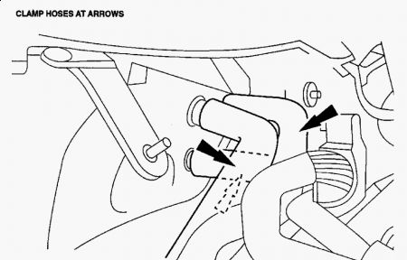
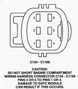
POWERS AND GROUNDS MUST BE VERIFIED AS ACCEPTABLE BEFORE CONTINUING. Start engine and ensure it is at full operating temperature. Set DATC to 90 °F (32 °C), with blower on high and recirculation and panel modes selected. Allow vehicle to remain in this mode for 5 minutes minimum. 1. Set DATC to 60 °F (15 °C), with blower on high and recirculation and panel modes selected. Allow vehicle to remain in this mode for 5 minutes minimum. 2. Measure the output temperature at the registers. Depending on local current atmospheric conditions, the coldest reading may be approximately 45 °F (7 °C). 3. If sufficient temperature drop is achieved across all registers within +/- 10 °F (6 °C), the vehicle is operating normally. No additional service is required. Stop procedure at this point and return vehicle to customer. a. If all or some measured outputs are greater than 45 °F (7 °C), or temperature difference between registers is greater than 10 °F (6 °C), continue with Step 4. b. NOTE: WITH THE DATC TEMPERATURE SET THE SAME IN BOTH ZONES, SOME LEVEL OF TEMPERATURE DIFFERENCE FROM DRIVER SIDE TO PASSENGER SIDE SHOULD BE CONSIDERED NORMAL. A DIFFERENCE OF UP TO 10 °F (6 °C) MAY BE OBSERVED DEPENDING ON AMBIENT TEMPERATURE, HUMIDITY LEVEL AND IN-VEHICLE TEMPERATURE. Open the hood and remove the cowl vent screen to gain access to the heater hoses at the heater core inlets/outlet. Refer to Workshop Manual, Section 501-02 for details. 4. Clamp off the three (3) heater hoses going into and out of the heater core, as close to the heater core as possible. Refer to Fig. 1 . 5. If A/C performance is restored, remove the clamps from the heater hoses and proceed to Step 7. If A/C performance is not restored, the concern is not caused by the DCCV. Remove the clamps from the heater hoses, restore the vehicle to original condition and refer to the Workshop Manual, Section 412-00 for further diagnostics. Do not continue with this article. 6. CAUTION: DO NOT SHORT THE ENGINE COMPARTMENT WIRING HARNESS C134 (LS) OR C1168 (THUNDERBIRD) PINS 3 OR 6 TO PINS 1 OR 4. DAMAGE TO THE DATC MODULE MAY RESULT IF THIS OCCURS. Shut off engine. Unplug C134/C1168 and check the resistance of the DCCV. Measure across pins 4-6, and pins 3-4. Refer to Fig. 2 and Fig. 3 . 7. If resistance is above or below 13-20 ohms, inspect C1034 at the DCCV for connection integrity, corrosion and damage. Repair as needed to restore. Verify repair by repeating Steps 1-3, and return vehicle to customer. a. If resistance is above or below 13-20 ohms and C1034 is not at fault, replace the DCCV, Part Number XW4Z-18495-AA. Refer to "Replacing the DCCV" at the end of this article for details. b. If resistance is acceptable, continue with Step 8. c. With C134/C1168 disconnected, verify available voltage to the DCCV. 8.
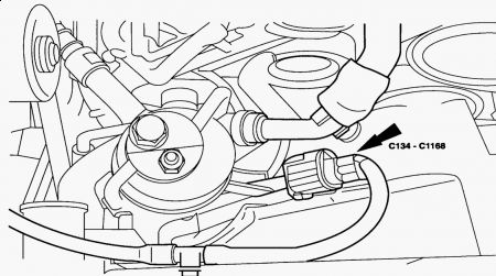
Start engine and set DATC to 60 °F (15 °C). Measure the voltage between the engine compartment harness (14290 side) C134/C1168 pin 4 and ground. 9. If voltage is less than 12 volts, check for open F101 or repair circuit 30-FB3 to restore voltage. Verify repair by repeating Steps 1-3, and return vehicle to customer. a. If voltage is greater than 12 volts, proceed to Step 10. Refer to Fig. 3 . b. With C134/C1168 disconnected, lift the lid on the Underhood FPDB (Front Power Distribution Box) and locate the power feed terminal at the drivers side, rear corner of the box. The lid must be lifted for the terminal bolt to be visible. 10. Verify DATC control assembly is providing a ground for the DCCV Solenoids. Start engine and set DATC to 60 °F (15 °C). 11. Measure voltage between the FPDB power feed and pin 3 of C134/C1168. If greater than 12 volts, proceed to Step 11d. a. If less than 12 volts, inspect circuit 91S-FB3 for high resistance or an open between C134/C1168 pin 3, and C228b (LS) or C228a (Thunderbird) pin 5, at the DATC control assembly. Repair wiring as required. Verify repair by repeating Steps 1-3, and return vehicle to customer. b. If circuit 91S-FB3 is OK, install a new DATC control assembly, Part Number XW4Z- 19980-CA (2000-2002 Lincoln LS), 1W6Z-19980-AA (2002 Thunderbird). Refer to Workshop Manual, Section 412-04 for details. Verify repair by repeating Steps 1-3, and return vehicle to customer. c. Measure voltage between the FPDB power feed to pin 6 of C134/C1168. If greater than 12 volts, the DCCV may have a mechanical concern internally. Replace the DCCV, Part Number XW4Z-18495-AA. Refer to "Replacing the DCCV" at the end of this article for details. d. If less than 12 volts, inspect circuit 91S-FB4 for high resistance or an open between C134/C1168 pin 6, and C228b (LS) or C228a (Thunderbird) pin 6, at the DATC control assembly. Repair wiring as required. Verify repair by repeating Steps 1-3, and return vehicle to customer. e. If circuit 91S-FB4 is OK, install a new DATC control assembly, Part Number XW4Z- 19980-CA (2000-2002 Lincoln LS), 1W6Z-19980-AA (2002 Thunderbird). Refer to Workshop Manual, Section 412-04 for details. Verify repair by repeating Steps 1-3, and return vehicle to customer. f. REPLACING THE DCCV - V8 ENGINES REMOVAL Drain the engine coolant. Refer to Workshop Manual, Section 303-03 for details. 1. Remove the air cleaner outlet pipe. Refer to Workshop Manual, Section 303-12 for details. 2. Remove the radiator upper sight shield. 3. Remove the passenger side upper radiator support bracket. 4. Disconnect the upper radiator hose from radiator. 5. Remove air conditioning receiver drier retainer and position aside. 6. Disconnect the auxiliary coolant flow pump electrical connector. 7. Remove the 2 (two) bolts from the auxiliary pump on radiator fan shroud. 8. Disconnect the heater hose at intake manifold and at the bottom of auxiliary pump. 9.
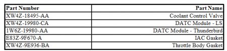
Remove the auxiliary coolant flow pump. 10. Raise the vehicle. 11. Remove the lower splash shield. 12. Remove the bolts for the DCCV bracket. 13. Lower the vehicle. 14. Remove the retainers for hydraulic cooling fan reservoir (passenger side of engine) and position aside. 15. Mark the heater hoses at the DCCV for identification and disconnect the 3 (three) quick disconnect fittings. Refer to Workshop Manual, Section 412-00. 16. Disconnect the DCCV electrical connector. 17. Disconnect the heater hose at upper radiator hose. 18. Remove the DCCV. 19. Transfer the hoses and bracket from old DCCV to new DCCV. 20. INSTALLATION Reverse the removal procedure to install new DCCV. 1. Torque the DCCV bracket bolts to 80 in-lb (9 N.m). 2. Torque the upper hydraulic cooling fan reservoir fastener to 53 in-lb (6 N.m) and lower/side fastener to 106 in-lb (12 N.m). 3. Torque the auxiliary coolant pump fasteners to 80 in-lb (9 N.m). 4. Torque the air conditioning receiver drier to 53 in-lb (6 N.m). 5. Refill the engine coolant. Refer to Workshop Manual, Section 303-03 for details. 6. Repeat Steps 1-3 of the diagnostic procedure to verify repair. 7. REPLACING THE DCCV - V6 ENGINES REMOVAL Drain the engine coolant. Refer to Workshop Manual, Section 303-03 for details. 1. Mark the heater hoses at the DCCV for identification and disconnect the 3 (three) quick disconnect fittings. Refer to Workshop Manual, Section 412-00 for details. 2. Remove the retainers for hydraulic cooling fan reservoir (passenger side of engine) and position aside. 3. Remove the throttle body. Refer to Workshop Manual, Section 303-04A details. 4. Remove the IAC (Idle Air Control) valve. Refer to Workshop Manual, Section 303-14 for details. 5. Disconnect the upper radiator hose from radiator and position aside. 6. Remove the air conditioning receiver drier retainer and position aside. 7. Disconnect the heater hoses from upper radiator hose T-fitting and water pump. 8. Disconnect the DCCV electrical connector. 9. Raise the vehicle. 10. Remove the lower splash shield. 11. Remove the bolts for DCCV at bracket. 12. Lower the vehicle. 13. Remove the DCCV valve with hoses and bracket attached. 14. Transfer the hoses and bracket from old DCCV to new DCCV. 15. INSTALLATION Reverse the removal procedure to install new DCCV. 1. Torque the DCCV bracket bolts to 80 in-lb (9 N.m). 2. Torque the upper hydraulic cooling fan reservoir fastener to 53 in-lb (6 N.m) and lower/side fastener to 106 in-lb (12 N.m). 3. Torque the air conditioning receiver drier to 53 in-lb (6 N.m). 4. Install the throttle body using a new gasket, Part Number XW4Z-9E936-BA. Refer to Workshop Manual, Section 303-04A for details. 5. Install the IAC using a new gasket, Part Number E83Z-9F670-A. Refer to Workshop Manual, Section 303-14 for details. 6. Refill engine coolant. Refer to Workshop Manual, Section 303-03 for details. 7. Repeat Steps 1-3 of the diagnostic procedure to verify repair. 8. PARTS INFORMATION PARTS INFORMATION
May 14, 2009 at 2:46 PM