You may need to read the codes, here's how:
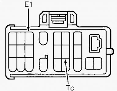
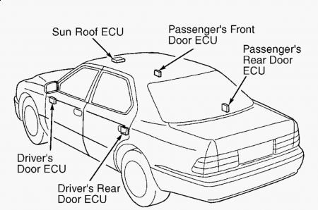
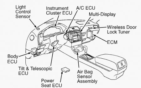
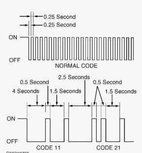
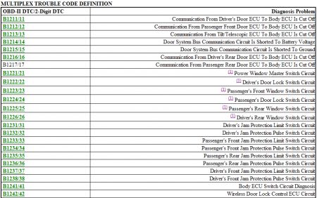
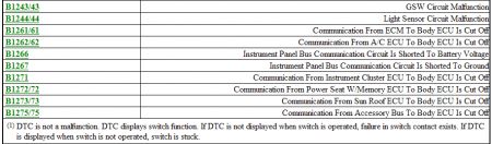
ARTICLE BEGINNING DESCRIPTION & OPERATION The multiplex control system consists of a body Electronic Control Unit (ECU) connected to 2 communication buses. The door system communication bus has driver's door ECU, passenger's front door ECU, driver's rear door ECU, passenger's rear door ECU, seat ECU (if equipped), sun roof ECU (if equipped) and tilt and telescopic ECU. The instrument panel system bus has instrument cluster ECU, A/C ECU, multi-display ECU and ECM. See Fig. 1 . Both buses are connected to body ECU through their own bus cut-relay. The multiplex control system is also equipped with a self-diagnostic function. Some electrical systems are directly connected to the body ECU, while some electrical loads and switches are connected to the appropriate ECU. Vehicle body electrical systems are controlled by serial communication in which each ECU is linked together by a single communication line. Once signals are received from door lock control switch or door courtesy light switch, each ECU determines the condition of the switches and doors. Each ECU converts the signal to digital signals and then outputs them to other ECUs. The body ECU receives these digital signals then determines the conditions of the switches and doors to use various controls to operate a specific system or motor. However, if there are no changes in input signals because doors are still closed or switches are not used within 30 seconds, the body ECU interrupts the communication to save battery power. After interruption, any changes in input signals will cause communication to resume. Fig. 1: Locating Multiplex Control System Components Courtesy of TOYOTA MOTOR SALES, U.S.A., INC. SELF-DIAGNOSTICS Body ECU Inspection 1. Apply water to windshield before operating wipers. Turn wiper switch to INT position. If wiper operates in INT position, go to next step. If wiper does not operate in INT position, inspect wiper/washer system. See WIPER/WASHER SYSTEMS article. If wiper/washer system is okay, replace body ECU. If wiper/washer is not okay, repair or replace components as necessary. 2. Open any door. Open door indicator light should glow. If open door indicator light glows, see WARNING: Deactivate air bag system before performing any service operation. See AIR BAG RESTRAINT SYSTEMS article. DO NOT apply electrical power to any component on steering column without first deactivating air bag system. Air bag may deploy. WARNING: Deactivate air bag system before performing any service operation. See AIR BAG RESTRAINT SYSTEMS article. DO NOT apply electrical power to any component on steering column without first deactivating air bag system. Air bag may deploy. READING DTCS WITH OPEN DOOR LIGHT or RETRIEVING DTCS WITH SCAN TOOL. If open door indicator light does not glow, repair or replace open door indicator light as necessary. READING DTC WITH OPEN DOOR LIGHT DTCs are displayed as flashes of open door indicator light. All open door indicator light DTCs are 2- digit numbers. Pay careful attention to length of pauses in order to read codes correctly. See Fig. 2 . DTCs from multiplex self-diagnostic system are retrieved through Data Link Connector 1 (DLC1). DLC1 is located in engine compartment on left side of engine. With key on engine off, connect jumper wire between DLC1 terminals E1 and Tc. See Fig. 3 . Fig. 2: Reading Open Door Indicator Light DTCs Courtesy of TOYOTA MOTOR SALES, U.S.A., INC. Fig. 3: Identifying DLC1 Terminals Courtesy of TOYOTA MOTOR SALES, U.S.A., INC. RETRIEVING DTCS WITH SCAN TOOL OBD-II DTCs from multiplex self-diagnostic system are retrieved through Data Link Connector 3 (DLC3). DLC3 connector is located under left side of instrument panel. Connect scan tool to DLC3. Turn ignition on. Retrieve DTCs. See scan tool manufactures instructions. If any code is present, perform test(s) in order given. See MULTIPLEX TROUBLE CODE DEFINITION table. MULTIPLEX TROUBLE CODE DEFINITION
Tuesday, September 22nd, 2009 AT 5:10 PM