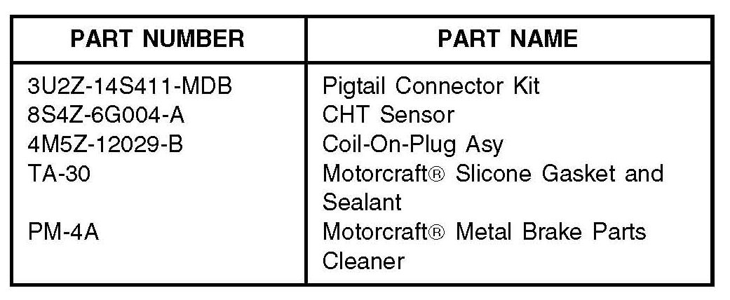
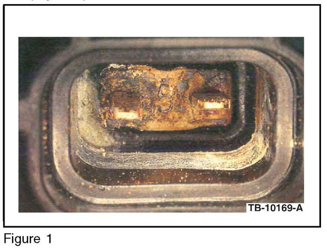
Ford has a technical service bulleting for this issue and you'll need to replace the sensor and the connector. Here is the official repair, and I've attached the part numbers and a view of a failed sensor.
MALFUNCTION INDICATOR LAMP (MIL) WITH
DIAGNOSTIC TROUBLE CODES (DTCS) P1285,
P1299, P0128, P0301, P0302, P0303, P0304, P0316
FORD:
2010-2012 Fusion, Escape, Transit Connect
LINCOLN:
2011-2012 MKZ
MERCURY:
2010-2011 Milan, Mariner
This article supersedes TSB 11-8-17 to update the vehicle model years and Issue Statement.
ISSUE
Some 2010-2012 Transit Connect vehicles equipped with 2.0L engine, 2010-2012 Fusion, Escape and 2010-2011 Milan, Mariner vehicles, equipped with a 2.5L engine or 2.5L Atkinson engine and 2011-2012 MKZ vehicles equipped with a 2.5L Atkinson engine may exhibit a MIL on with DTC(s) P1285, P1299 and/or P0128. Engine temperature may be cold and report as hot or be hot and report as cold. Engine cooling fan operation may also be affected by the incorrect cylinder head temperature (CHT) sensor reading - turning on or off at inappropriate times. These vehicles may also exhibit rough run, lack of power, MIL on with DTCs P0300, P0301, P0302, P0303, P0304, and/or P0316.
ACTION
Refer to service procedure to correct the condition.
SERVICE PROCEDURE
Engine temperature concerns may be due to corrosion at connector C1164.
1.Inspect the cam cover trough, making sure it is clear of debris like leaves, wasps, dirt and the drain hole by cylinder 4 is open.
2.Inspect connector C1164 at CHT sensor for evidence of water contamination.
a. If evidence of water contamination is present, proceed to Step 3.
b. If water contamination is not evident, do not continue with this procedure. Refer to Powertrain Controls/Emissions Diagnosis (PC/ED) Manual, pinpoint test DL1 for normal diagnostics.
3.If corrosion from water contamination is severe and terminals are rusted and disintegrated: (Figure 1)
a. Cut off connector C1164 and install a new pigtail connector. Refer to instruction sheet.
b. Replace the CHT sensor. Refer to Workshop Manual (WSM), Section 303-14. Proceed to Step 4.
4.If corrosion is not severe, remove any water and thoroughly clean connector C1164 and the CHT sensor.
5.Before reattaching the CHT sensor cover to the cam cover, clean the cam cover and CHT sensor cover with Motorcraft Metal Brake Parts Cleaner.
6.Attach the CHI sensor cover to the cam cover and add Motorcraft(R) Silicone Gasket and Sealant around the CHI sensor cover, to seal and prevent water entry.
Driveability concerns may be due to water entry into the spark plug wells, affecting ignition coil-on-plug(s) performance.
1.Inspect the cam cover trough, making sure it is clear of debris like leaves, wasps, dirt and the drain hole by cylinder 4 is open.
2.Remove the ignition coil-on-plugs and check for water in the spark plug wells.
a. If evidence of water contamination is present, proceed to Step 3.
b. If water contamination is not present, do not continue with this article. Refer to PC/ED Manual, pinpoint test DL1 for normal diagnostics.
3.Dry out the spark plug well(s).
4.Replace the affected ignition coil-on-plug(s), refer to WSM, Section 303-07 - Engine Ignition.
a. Be sure to center the ignition coil-on-plug in the bore. When tightening the last mounting fastener, the coil might become pressed to one side, biasing the seal to one side of the spark plug well, over the other.
b. Do not use RTV silicone sealant or dielectric grease on the boot. The spark plug boot-to-spark plug well seal is designed to breath through the molded notches in the rubber boot, to allow gases to pass freely in and out of the spark plug bore.
Images (Click to enlarge)
Sep 20, 2019 at 10:13 AM